Week 12
Output Devices
Group assignment
- Measure the power consumption of an output device
- Document your work (in a group or individually)
Individual assignment
- Add an output device to a microcontroller board you've designed and program it to do something
LCD display
In my final project i am going to have a LCD screen to display how fast my turbine is turning and how much electricity it is producing. That is why this week i going connect a LCD display and program it
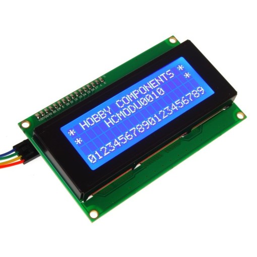
As we all know, though LCD and some other displays greatly enrich the man-machine interaction, they share a common weakness. When they are connected to a controller, multiple IOs will be occupied of the controller which has no so many outer ports. Also it restricts other functions of the controller. Therefore, LCD2004 with an I2C bus is developed to solve the problem. I2C bus is a type of serial bus invented by PHLIPS. It is a high performance serial bus which has bus ruling and high or low speed device synchronization function required by multiple host system. I2C bus has only two bidirectional signal lines, Serial Data Line (SDA) and Serial Clock Line (SCL). The blue potentiometer on the I2C LCD2004 is used to adjust backlight to make it easier to display on the I2C LCD2004.
That is why my plan is to use a i2c 2004 LCD display
https://www.amazon.com/SunFounder-Serial-Module-Display-Arduino
- I2C Address: 0x20-0x27(0x20 default)
- Number of Characters: 20 characters x 4 Lines
- Blue LED backlight with white char color
- Adjustable contrast
- Supply voltage: 5V
- Interface: IIC/TWI
- View direction: Wide viewing angle
- Dot size: 0.55 x 0.55 mm / Dot pitch: 0.60 x 0.60 mm
- Character size: 2.96 x 4.75 mm /Character pitch: 3.55 x 5.35 mm
- Size: 98x60x24mm
- Weight: 75g
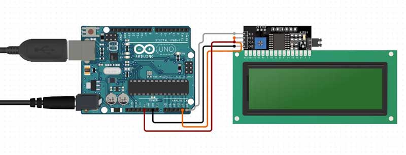
| I2C LCD2004 | SunFounder Mars board |
|---|---|
| GND | GND |
| VCC | 5V |
| SDA | A4 /pin 20 mega2560 |
| SCL | A5 /pin 21 mega2560 |
2) To be able to send a program to our LCD screen we will need to setup a Library for it so we can speak to the LCD screen. We can download it from this site.
https://bitbucket.org/fmalpartida/new-liquidcrystal/downloads/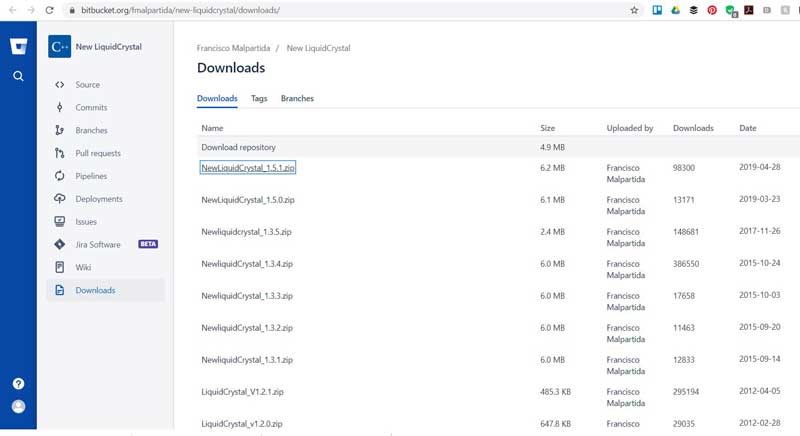
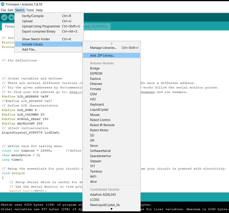
3) After we have dowloaded the zip file we include it in our Library by adding it to the Arduino.
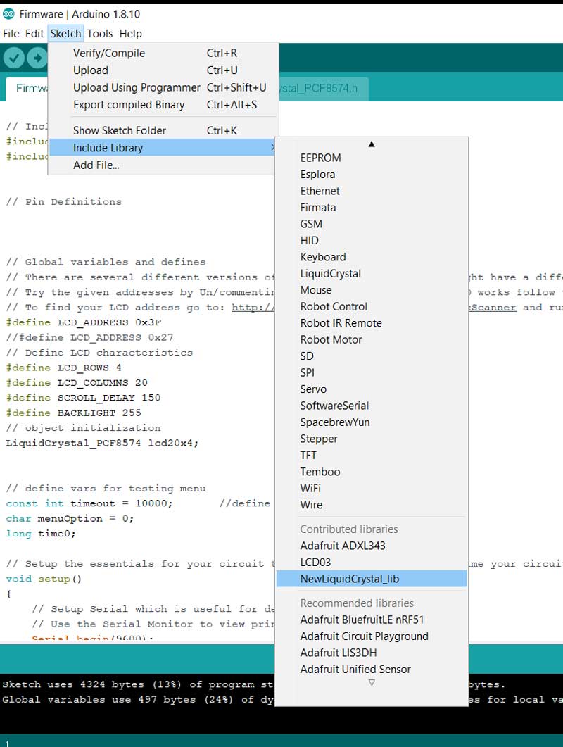
4) When the library has installed we have to select it from the library list.
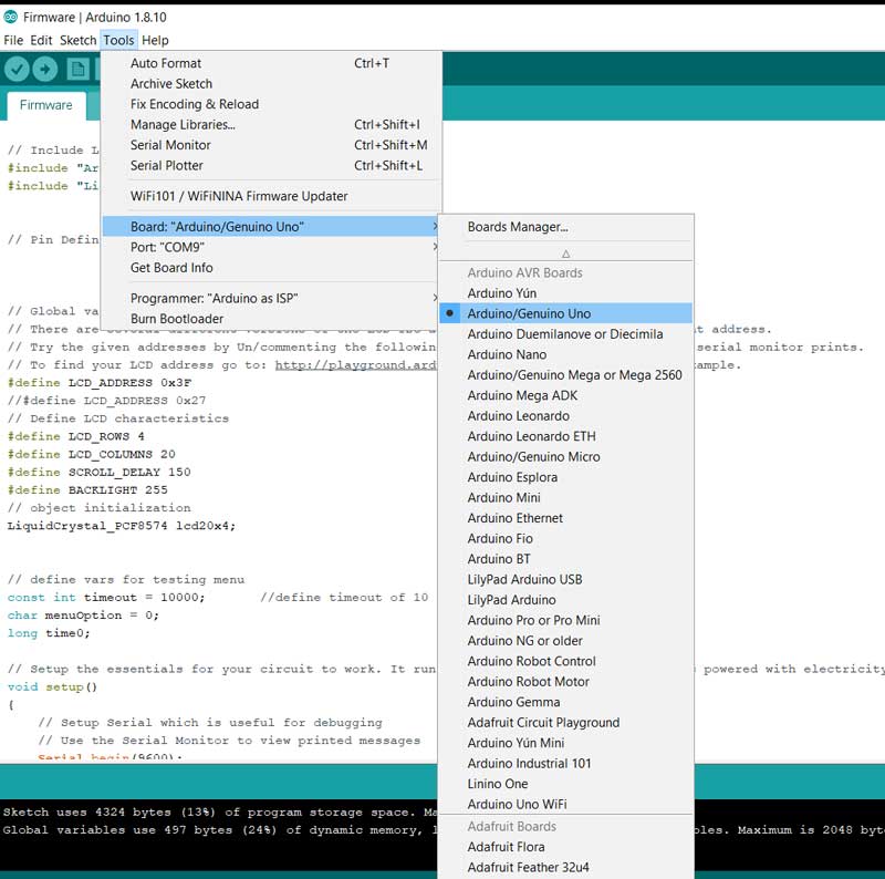
5) We select the board we are using
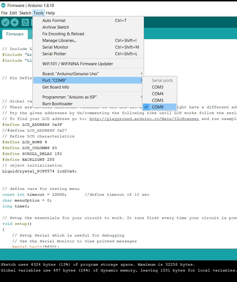
6) Then we are almost ready we just have to select the correct COM port we are using to comunicate with the board
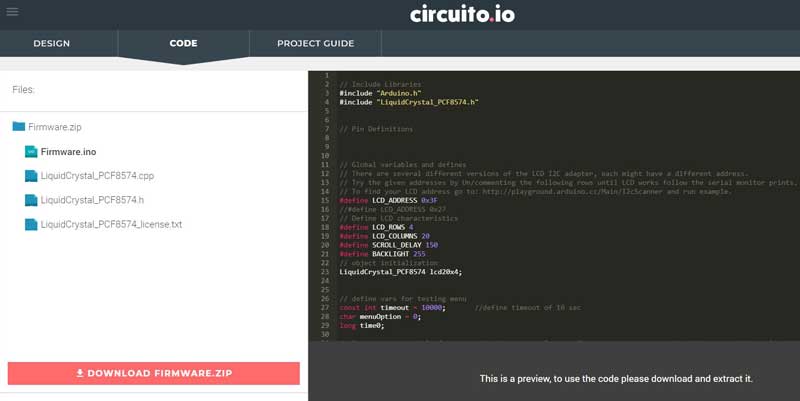
To get a code to test out my board I found this code on circuito.io
https://www.circuito.io/app?components=9442,11021,417987
6) In the Arduino program we press the upload button to send the file to our board and it has to include the library files to make it work.
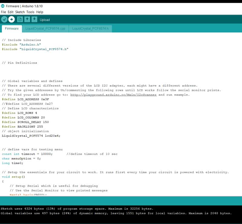
If "Done uploading" appears at the bottom of the window, it means the sketch has been successfully uploaded. Then finally we can see if it works!!