Week 18 - Mechanical design and machine design
This week resumed the lectures on mechanical design and machine design. It surveyed the wild types of mechanical parts that are available on the market and the many ways to assemble them with actuators and sensors.
FAB ACADEMY 2020 source source
20200527 machines from Academany on Vimeo.
My Assignment
In the previous years, the topic of this week, i.e. mechanical design and machine design, was meant to be covered into two weeks. This week assignment will really be challenging. Quentin Bolsee and I are only two to build a complete and functional machine. On one of our supervisor advise, Denis Terwagne, we decided to build a machine inspired by the Urumbu project, a CNC Mini-milling machine to mill small PCBs (5 cm x 5 cm). The mechanical design of this machine is based on flexible parts, particularly a flexible plate that allows displacement along x and y axes. The particularity of this flexible design is that the displacement along x and y axis are decoupled. Also, this type of mechanism is claimed to have no backlash, clearance or hysteresis contrary to cycloidal or involute teeth gears.
Because most of the time seeing things helps more than many words here is a spoiler video showing the final result of our machine performing a little square.
Our machine performing a little square
To achieve this result Quentin and I agreed to split the work in such a way: Quentin would work on the Electronics and programming while I would do the Mechanical Design. In the following sections, we'll have a look on the mechanical design, the bill of materials, the assembly, the electronics and programming and the results. Finally we'll share our files with whom would be interested to reproduce it.
To have more general informations about this project, please follow this link to the group assignment.
Mechanical Design
Once again let's first see at the final mechanical design.
Assembly of the machine
The first thing I made is to clone the Urumbu git repository.
This repository contains two important OpenSCAD files: one for the Flexible plate and one for the spring.
Flexible plate
This concept was introduced in 2004 by Shorya Awtar in Synthesis and Analysis of Parallel Kinematic XY Flexure Mechanisms. It was also studied by the Precision Systems Design Lab (Prof. Shorya Awtar) at the University of Michigan, Ann Arbor (see the video here). Metamaterials are a promising topic whose exploration was eased by digital fabrication, many researches are done in this field and many BYU Compliant Mechanisms are shared by the community.
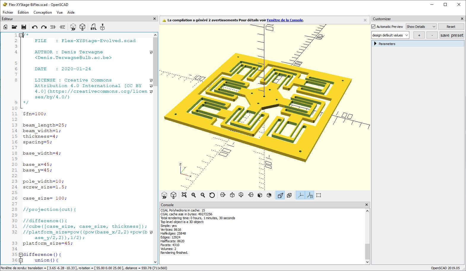
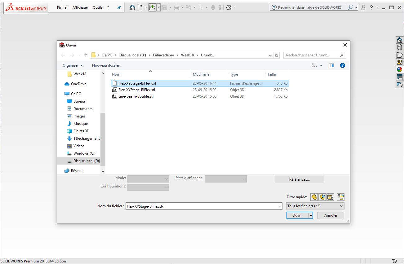
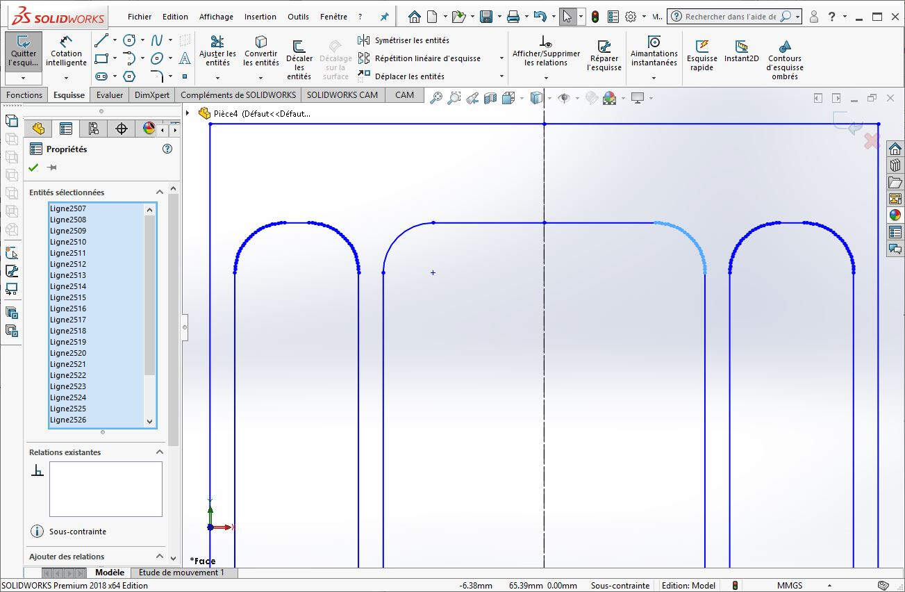
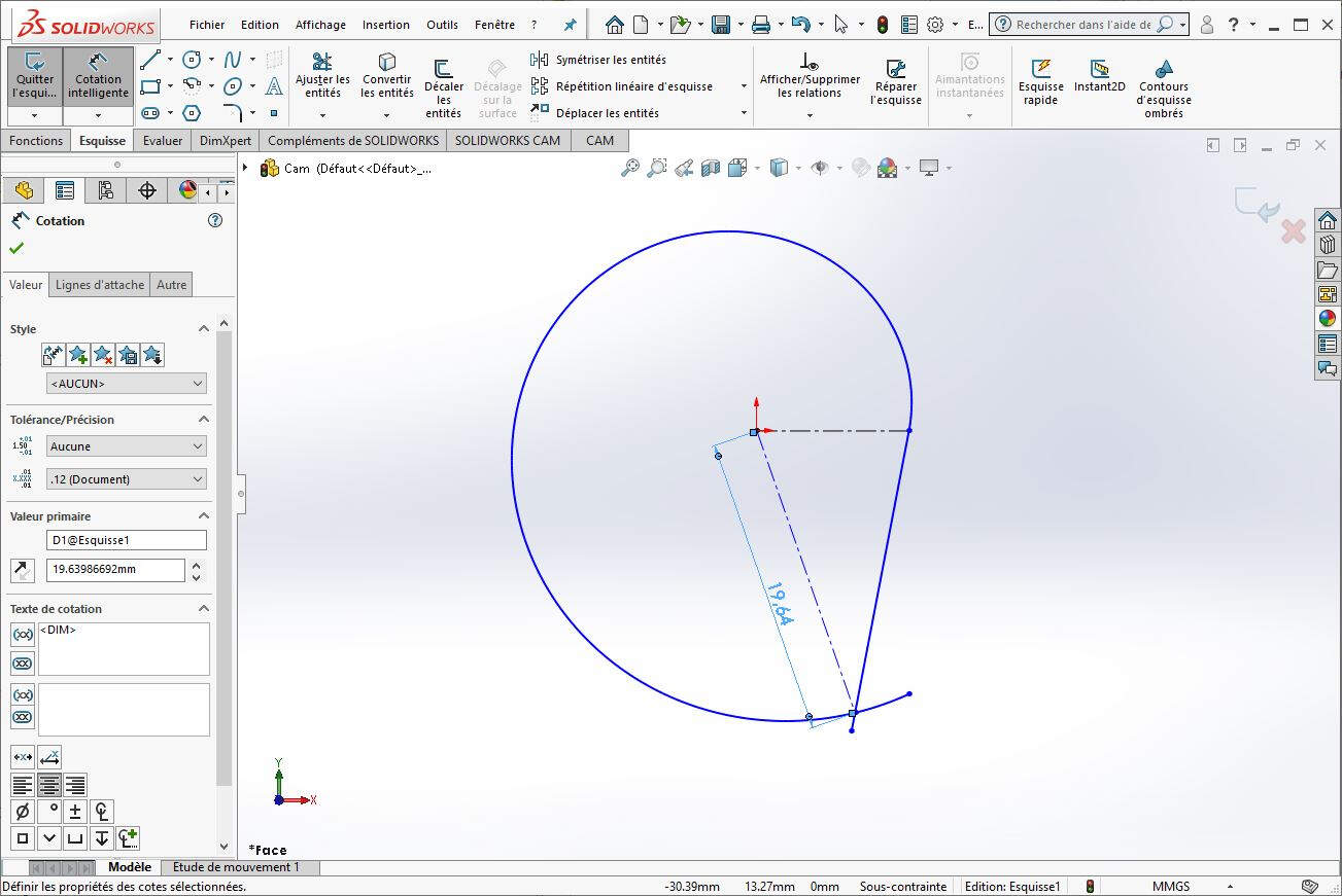
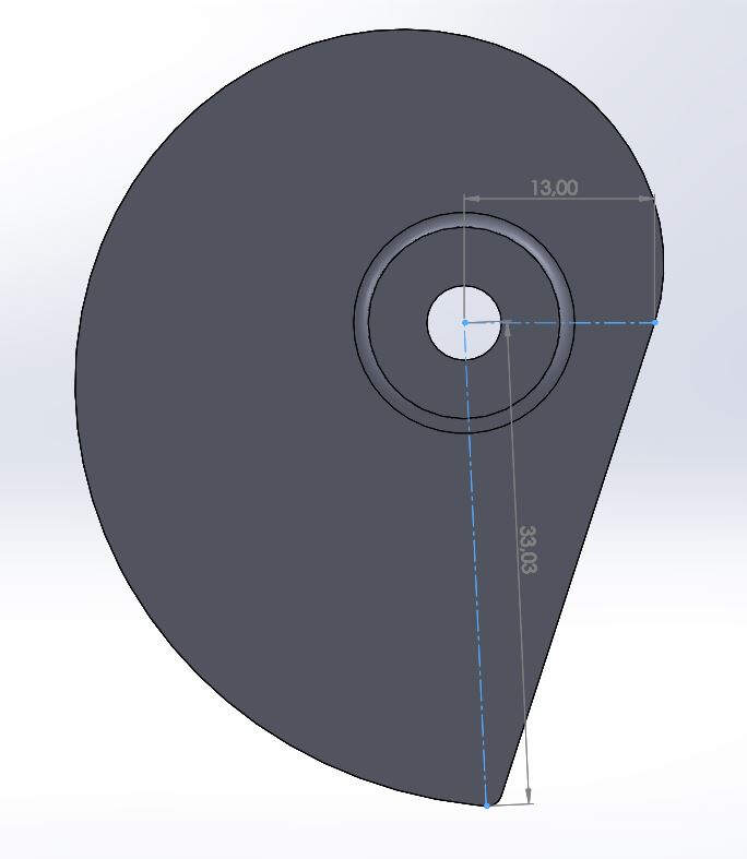
To build our flexible plate we used the OpenSCAD files provided in the the Urumbu git repository. To be able to use them I first installed OpenSCAD. With the help of this documentation I created a projection that I exported as a .DXF file to use it as a draft in SolidWorks.
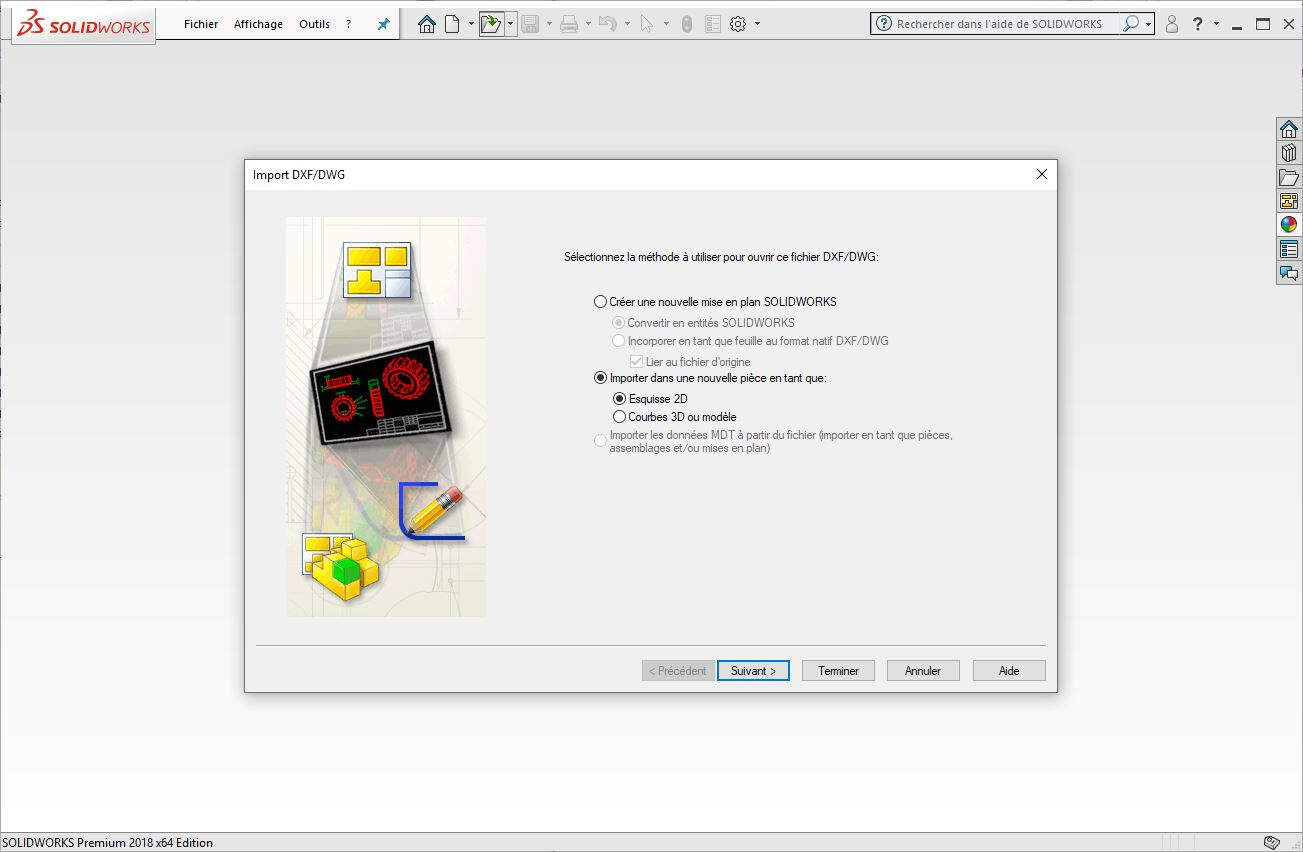
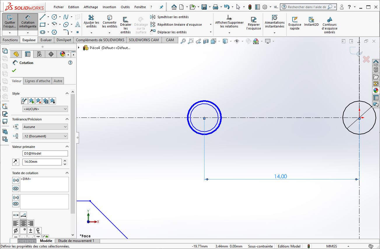
In SolidWorks I opened the DXF file.
I selected import as a 2D draft.
I selected the units -> mm.
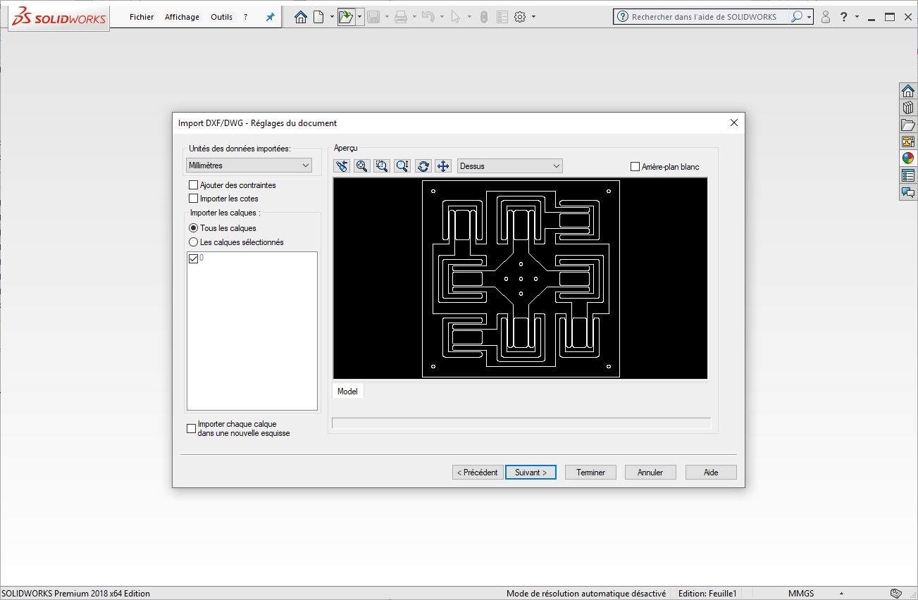
Then I clicked on Finish.
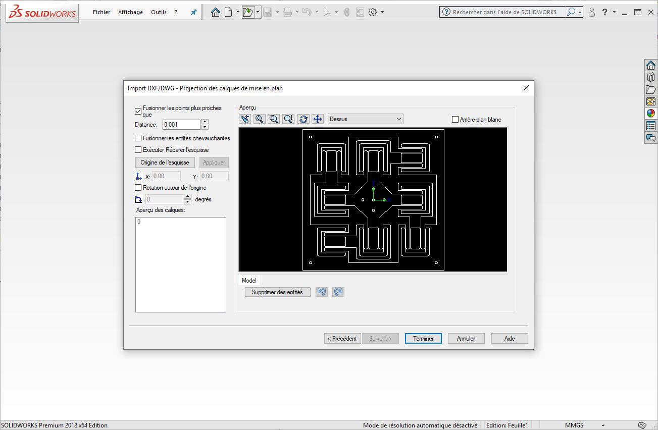
Here is the result after these steps.
When I started to set the dimensions of the draft I got the following message.
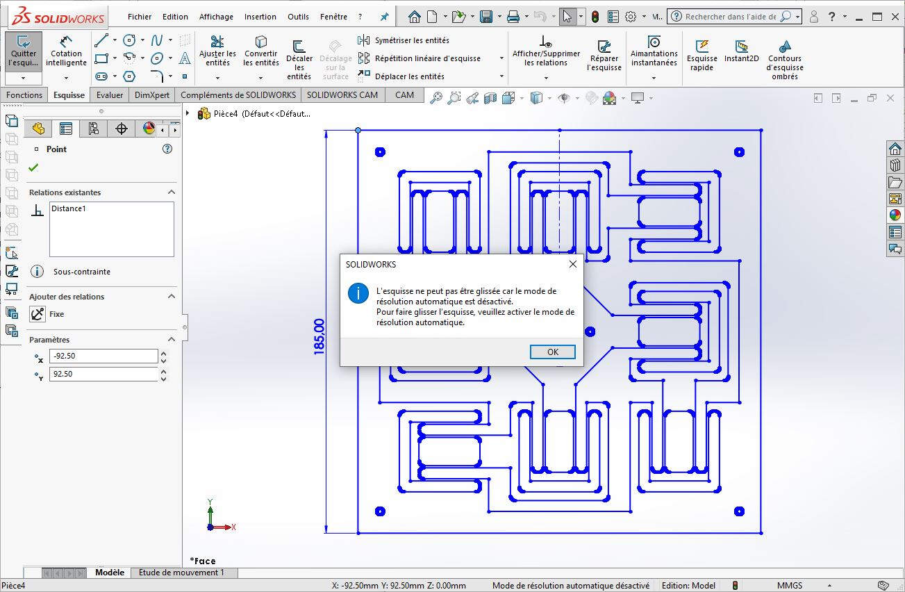
To solve that issue I had to enable the Automatic Solve mode.
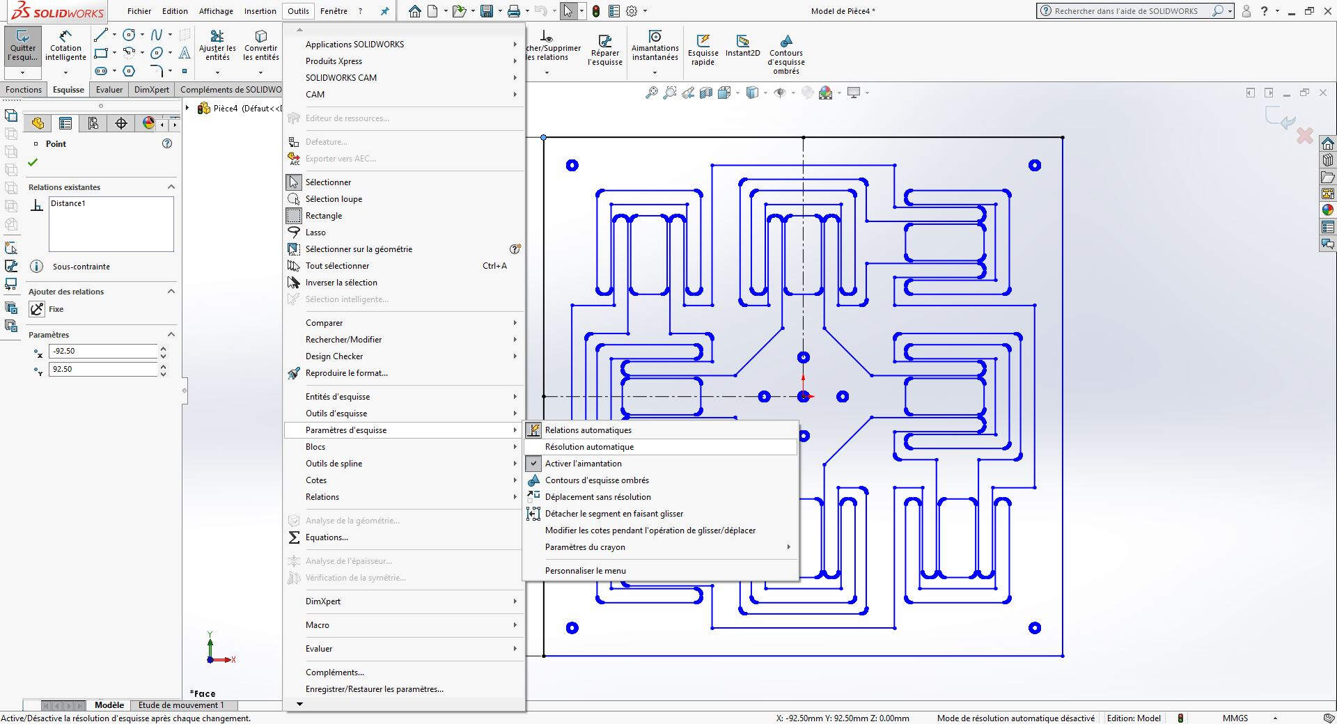
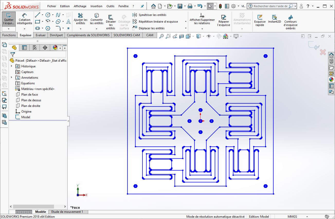
I also had to properly redraw the curves.
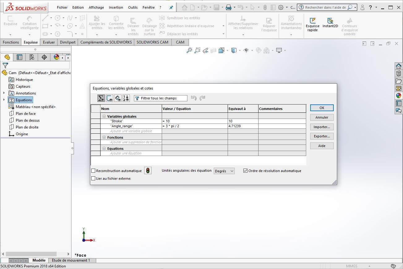
And I added parametric tuning of the plate.
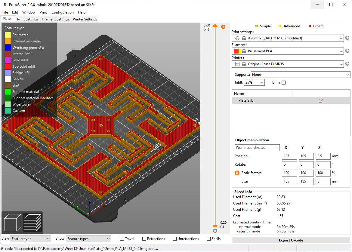
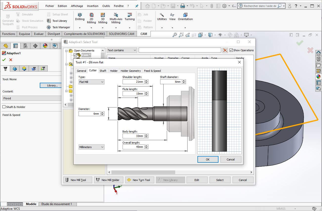
Once this work finished I printed the plate. I first prepared the file with Prusa Slicer.
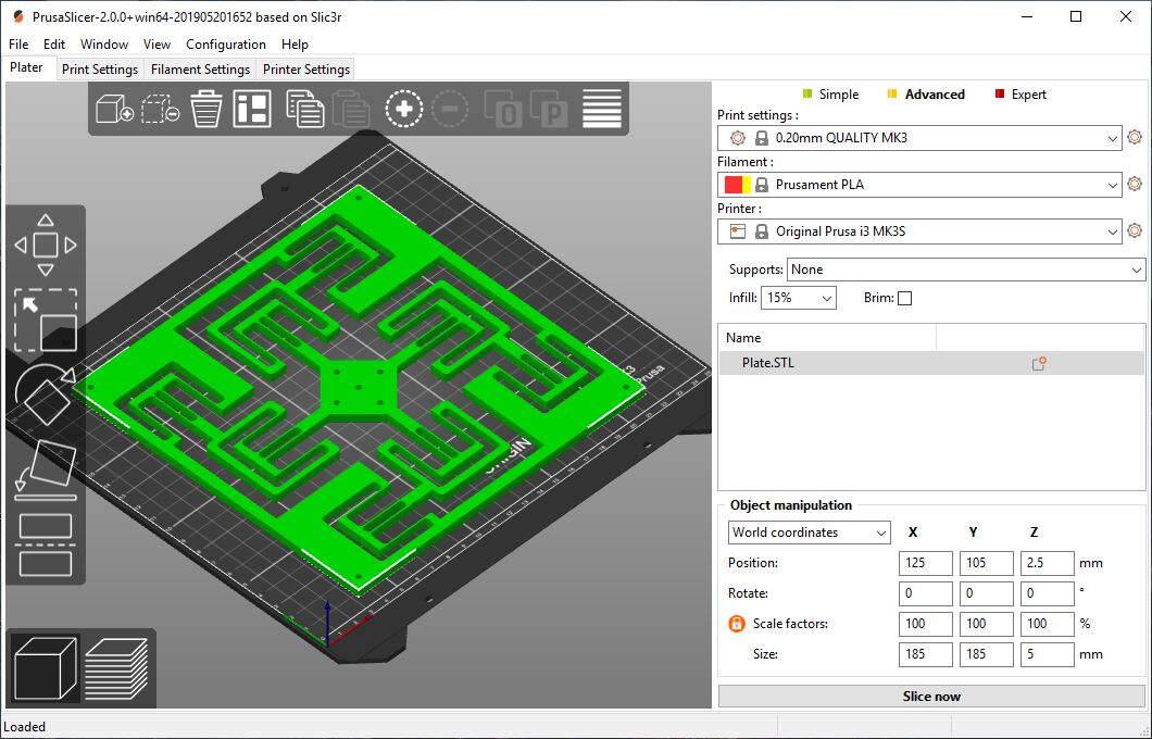
Here is the estimation of the printing time.
Here is a picture of the Prusa printer printing the flexible plate.
.jpg)
An important parameter in this flexible mechanism is the thickness of the material. That's the reason why I printed two different flexible plate: the first one is 5mm high while the other is 4mm high. The second one was more flexible.
.jpg)
Here is a picture of the flexible plate mounted on the machine. Thanks to the springs the plate is kept at the right position at one extremity of the board. Therefore it has the right flexibility.
.jpg)
Cams
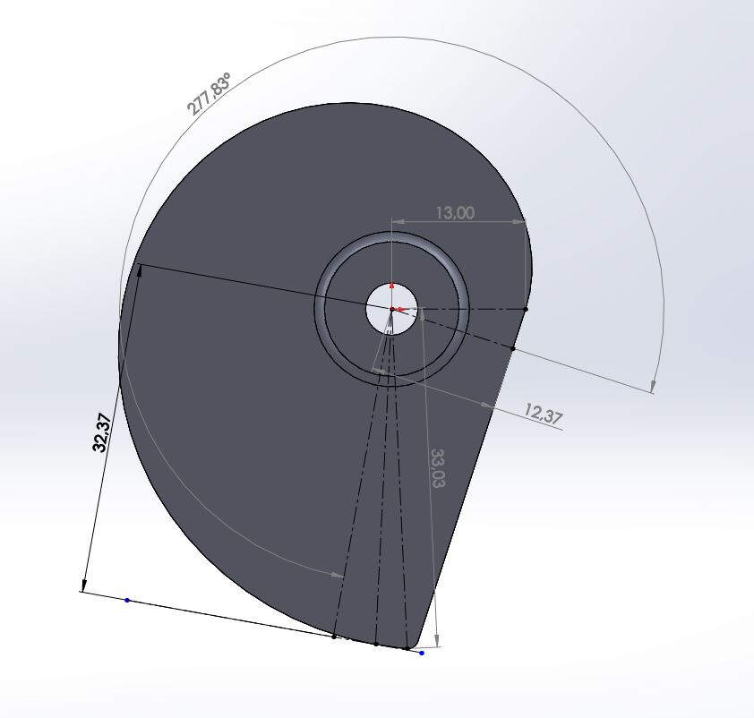
To control the position of the plate with two stepper motors we decided to design two cams with a shape of a spiral such that the linear motion of the plate in one direction is proportional to the circular motion of the motor. To do that I also used parametric design. I first set the stroke to 10mm (but later I'll change it to 20mm) and the angle range of the stepper motor as big as possible with respect to the shape of the cam.
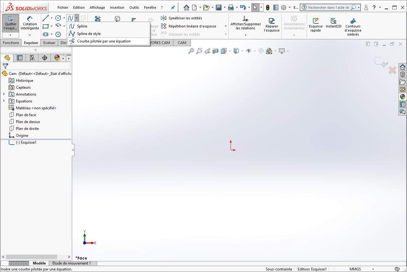
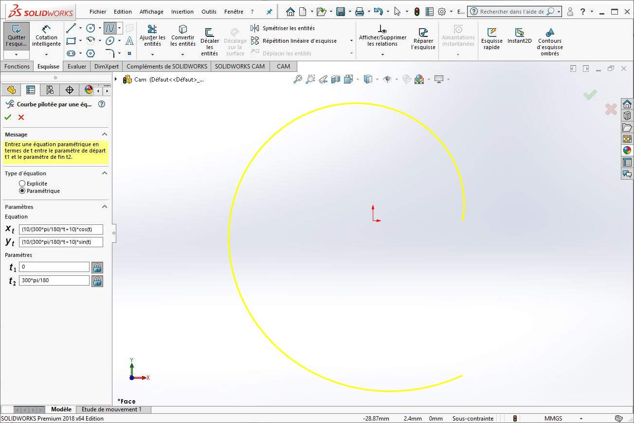
To draw the cam I used an Equation Driven Curve.
The equations of the curve are the following:
\begin{align} x_t & = (\frac{20 t}{300 \pi/180}+10)\cos(t)\\ y_t & = (\frac{20 t}{300 \pi/180}+10)\sin(t) \end{align} with \(t \in \begin{bmatrix}0&\frac{300\pi}{180}\end{bmatrix}\)
Then I drew a line to close the shape.
And I adjusted the dimensions.
I extruded the shape.
Here is the result.
We first wanted to mill the cam but because of a lack of time we decided to 3D print it instead.
As I said earlier, thanks to parametric design, I was able to change the stroke of the cam from 10mm to 20mm (in the equations above, I already changed the stroke to 20mm).
By optimizing the dimensions of the cam, I was able to increase the motor motion range to 277.83°
Then I printed the cams with many other parts.
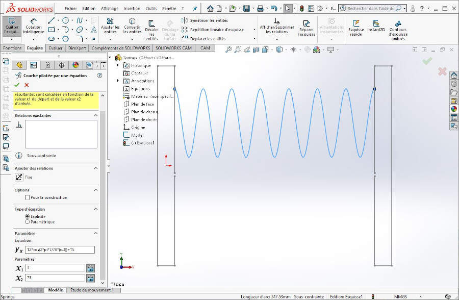
Springs
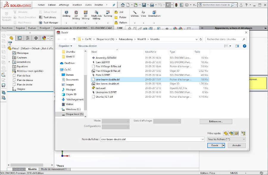
For the springs I also exported the DXF files from the original files of the Urumbu project.
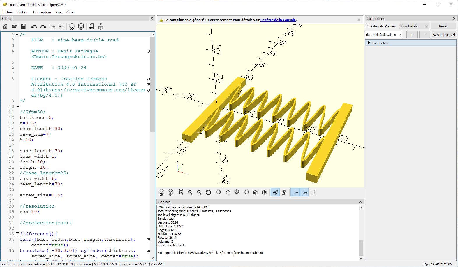
I opened it in SolidWorks.
And I decided to draw it again...
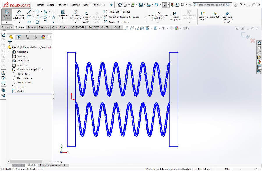
...using equation driven curves.
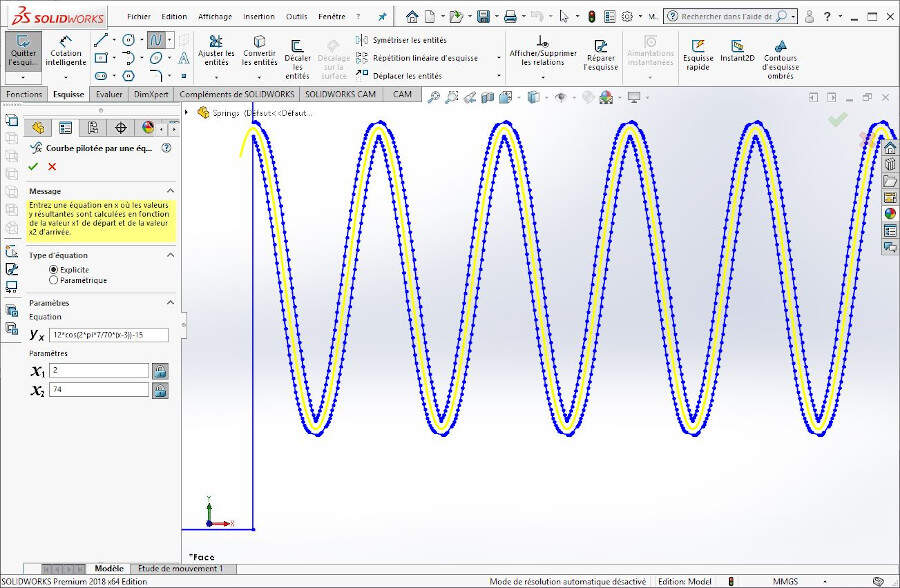
The equation was the following:
\[ x_t = A \cos(2\pi\frac{N_W}{L}(t-3))+15 \] \[ x_t = 12 \cos(2\pi\frac{7}{70}(t-3))+15 \] where \(t \in \begin{bmatrix}3&73\end{bmatrix}\), \(A\) is the wave amplitude, \(N_W\) is the number of waves and \(L\) is the length of the spring at rest position.
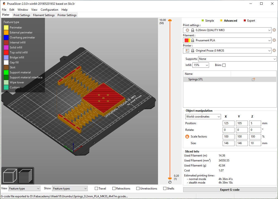
I also printed the springs as shown in the following picture.
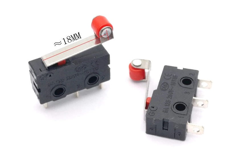
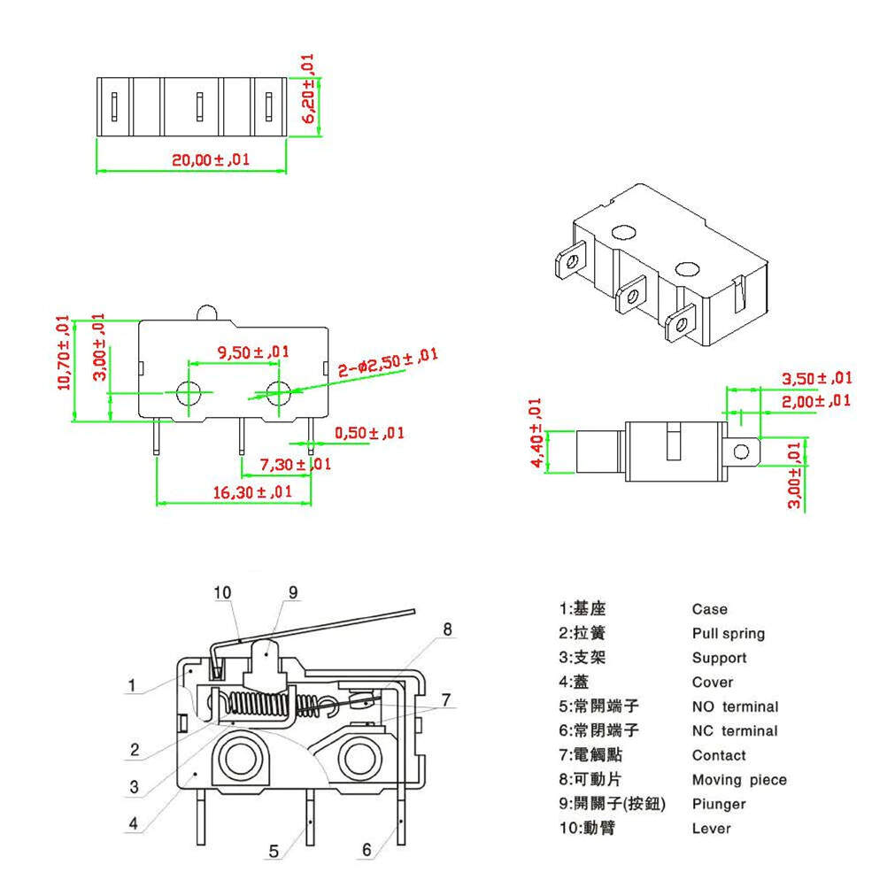
Microswitches
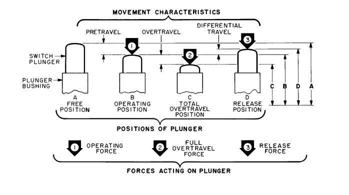
To position accurately the microswitches on the machine in such a way that they would be activated exactly when the start/end of the stroke would be reached, I searched for the datasheet of the microswitch 10T85. Unfortunately I was not able to find it. As a consequence I had a look on other microswitches datasheets to know which characteristics define such sensors. I found several operating characteristics: the Free Position (F.P.), the Full Overtravel Force, the Operating Position (O.P.), Operating Force (O.F.), the Overtravel (O.T.), the Pretravel (P.T.), the Release Force (R.F.) and the Total Travel (T.T.). All theses operating characteristics are explained here and the most important ones are depicted in the following picture.
Motors
The motors we used where stepper motors 17HS15-0404S.
.jpg)
Here is the datasheet.
.jpg)
Motors and switches support
To attach the motors and the microswitches I designed a support plate that I 3D printed.
.jpg)
Sliding plate
For the sliding plate, the plate on which the flexible plate slides, we used an acrylic sheet of 5mm thick. This materials state of surface is much less rough than the finished state of surface of a 3D printed PLA part. As a consequence the flexible plate will easily slide on the sliding plate.
The only option we had to make that part was 2D milling.
Brass Threaded Inserts
To mount the cams on the motor shafts we used M3 threaded inserts.
.jpg)
We inserted them with a soldering iron.
.jpg)
This video shows the procedure.
How to place threaded inserts
As PLA is liquid at 216°C we used a temperature of 180°C to gently melt it while inserting the M3 threaded inserts. We also used that technic to assemble the machine spacers, the machine stage and the electronics enclosure.
.jpg)
.jpg)
.jpg)
.jpg)
.jpg)
.jpg)
Bill of materials
Actuators and sensors
| # | Name | Qty |
|---|---|---|
| 1 | Stepper motor 17HS15-0404S - datasheet | 2 |
| 2 | 10T85 Microswitch | 4 |
Parts
| # | Name | Qty | Material |
|---|---|---|---|
| 1 | Plate | 1 | PLA |
| 2 | Underplate | 1 | PLA |
| 3 | Flexible plate | 1 | PLA |
| 4 | Under-flexible plate | 1 | PLA |
| 5 | Sliding Plate | 1 | Acrylic sheet (thickness - 5mm) |
| 6 | Springs plate | 1 | PLA |
| 7 | Collision plate | 1 | PLA |
| 8 | Cam in spiral | 2 | PLA |
| 9 | Switch elevator | 4 | PLA |
| 10 | Motors and switches support | 1 | PLA |
| 11 | Electronics enclosure | 1 | PLA |
| 12 | 20mm spacer | 4 | PLA |
| 13 | 39mm spacer | 4 | PLA |
| 14 | Base | 4 | PLA |
| 15 | Base plate | 1 | Plywood (thickness - 8mm) |
| 16 | PCB spacer | 9 | PLA |
Screws
| # | Type | Qty | Used for |
|---|---|---|---|
| 1 | M3 x 10mm Cross Recessed Flat Head Machine Screw |
4 | Motor 1 |
| 2 | M3 x 10mm Cross Recessed Flat Head Machine Screw |
4 | Motor 2 |
| 3 | M3 x 12mm Socket Head Cap Screw |
4 | Springs |
| 4 | M3 x 30mm Cross Recessed Flat Head Machine Screw |
4 | Electronics Enclosure |
| 5 | M3 x 16mm Socket Head Cap Screw |
4 | Base |
| 6 | M3 x 12mm Socket Head Cap Screw |
8 | 4 Microswitches |
| 7 | M3 x 8mm Socket Head Cap Screw |
2 | 2 Cams |
| 8 | M3 x 30mm Cross Recessed Flat Head Machine Screw |
4 | Four axes |
| 9 | M3 x 40mm Socket Head Cap Screw |
4 | Plate |
| 10 | M3 x 16mm Socket Head Cap Screw |
9 | PCBs |
| 11 | M3 Hexagon Nut | 9 | PCBs |
| 12 | M3 Flat Washers - RS Components | 9 | PCBs |
| 13 | M3 Brass Threaded Insert - RS Components | 9 | 3D printed parts |
| 14 | M3 x 12mm Socket Head Cap Screw |
4 | PCB - Switches |
Assembly
The assembly of the machine is quite easy and shown in the following video.
Assembly of the machine
To be able to mount the microswitches I first had to cut threads.
.jpg)
.jpg)
.jpg)
.jpg)
The bases are mounted on the wood plate and screwed in the machine spacers.
.jpg)
.jpg)
.jpg)
.jpg)
Then I mounted the electronics as shown on the following pictures.
.jpg)
.jpg)
And here is the final result.
.jpg)
On the following pictures you'll see how the electric cables are guided.
.jpg)
.jpg)
Hereinafter you'll see a zoom on the cams and the microswitches.
.jpg)
Electronics and programming
This part of the work was mostly done by Quentin Bolsee who created an original strategy to connect and control the motors. He designed the electronics and he programmed it. For more details about this topic please refer to this page.
The following pictures show the 12v dc power supply and the female jack socket.
.jpg)
.jpg)
.jpg)
Results
First test
Final result
Final result