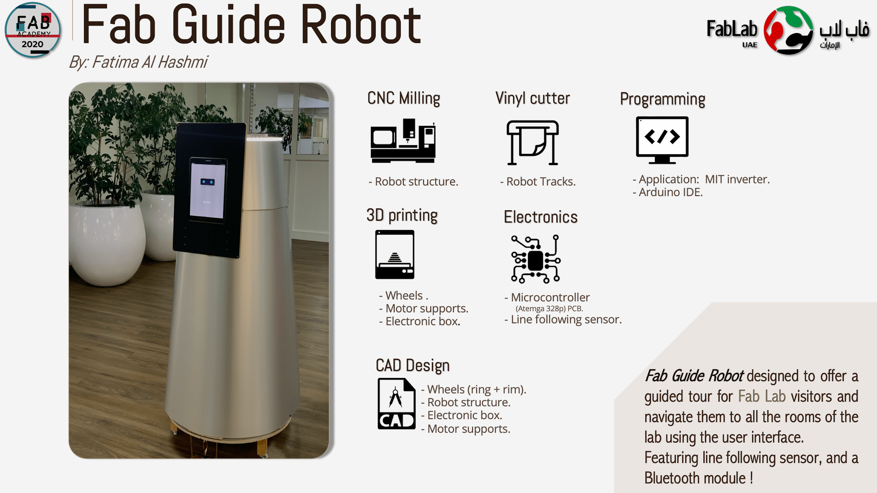
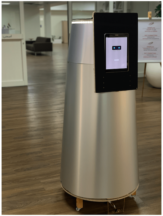
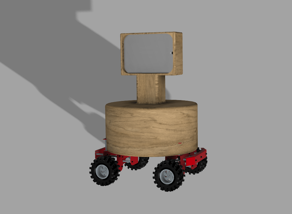
For the final project I decided to build a mobile robot that is able to give a guided tour for Fab Lab visitors and navigate them to all the rooms at the lab.
Working principle:
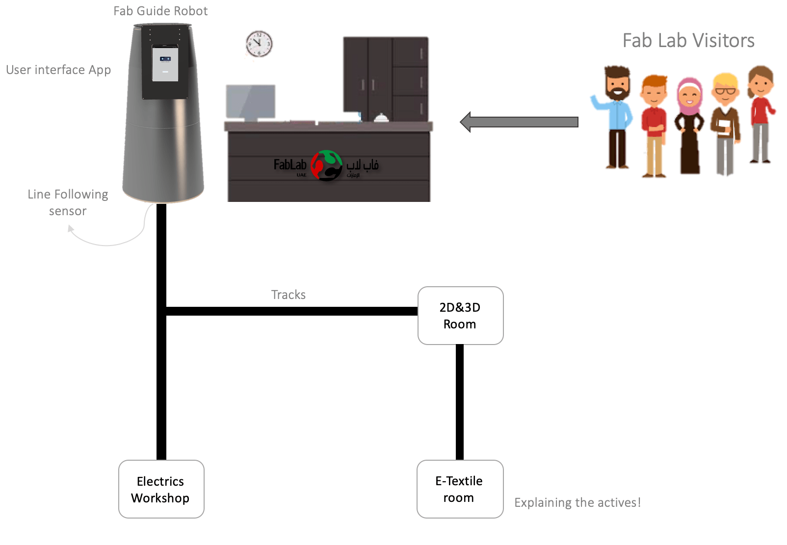
The visitors will enter the fab lab reception, the robot will greet them. Then in the tablet attached to the robot, there is an App. Users can select where to go, then they will follow the robot to the selected room. Afterward, the robot will start to describing and explaining the machines and the actives occur in the room.
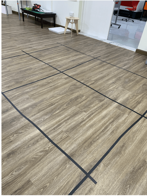
For robot navigation, I used the Localization by line tracking system technique. I build an arena of tracks with an intersection point, each intersection will represent a location.
There is a line following sensor attached to the robot to sense the lines. Subsequently, the robot is connected to the application to chose different points.
Here some additional reasons why I build this robot:
As I noticed they had a lot of visitors came to the lab, and each time they are explaining to them the actives and machines. Thus, using the the robot will be interesting for the visitors special for the kids. In the same time, they can explain the digital fabrication techniques used in the robot.
I think Fab Academy is the chance to learn and exploring new things to gain a new skills.
To conclude this Point:
The main objective is not only to navigate the visitor, as the lab is small. but is to explain the activities, learn new things, and, to use the robot for learning purposes in the future if they wish.
Project Objectives:
What will it do?
I want to build a Robot that gives a guided tour for Fab Lab visitors and navigate them to all the rooms at the lab (service robot).
Who has done what beforehand?
Similar Robots used to guide users:
LG Airport Guide Robot ‘AirStar’
LoweBot Robot
What will you design?
A Mobile Robot:
CAD Design:
Robot structure
Motor holder
Wheels design
Chassis
Tracks
Supports.
Electronics box.
PCB Design for:
What materials and components will be used? What parts and systems will be made? What processes will be used?
Plywood: for robot structure, Chassis, and, Tablet holder using CNC milling
Acrylic: for some parts in the robot using laser cutting.
HDPE: for Tablet holder using CNC milling.
Aluminum sheet: for covering the robot, the outer structure using laser cutting.
Flexible filament: for Wheels tire using 3D printing.
PLA filament: for Wheels rim, electronics box, motor support, robot support , and, sensor cover using 3D printing
Vinyl Sticker: for robot tracks using Vinyl cutter
Inputs:
Outputs:
Others:
Motor Driver.
Power Supply: Battery.
Microcontroller: ATemga 328p.
Tablet
Where will they come from?
Seems all the components and materials I needed are available in the lab. if I found something not available I will order it.
What questions need to be answered?
How will it be evaluated?
I will be happy, If the robot navigates visitors correctly, and can detect the objects to avoid collisions. Moreover, be able to give a guided tour of the lab, and explain different actives happens at the lab.
What are the implications?
In the future, I want to improve the robot to make it fully functional. Moreover, I would love it if the robot can be used on larger scales than the lab. Also, I want to try different location techniques for robot.
Even after finishing Fab Academy Diploma, I want to continue working and improving the features and technics available in the robot. besides, to improve the robot design. Also, I hope to add some Artificial intelligence features to the robot if possible.
Also, I will try to add some fun features for it, thus kids will be excited and enjoy learning more about robotics Since this robot had basic features and concepts. I think it will be a good start to learn the basics concepts for robotics or electronics.
| Qty | Description | Price ($) | Supplier |
|---|---|---|---|
| 2 | DC Motors | ~ 08.00 | From Ali |
| 1 | L298N Motor Drive | ~ 02.00 | Fab Lab UAE |
| 1 | LED strip | ~ 08.00 | Fab Lab UAE |
| 1 | Aluminum Sheet Satin Silver | 83.97 | bluerhine.store |
| 2 | Support wheels | ~ 04.00 | |
| 1 | Wood/Plywood sheet | ~ 27.00 | Fab Lab UAE |
| 1 | Acrylic(Matte 3mm + Clear 10mm) | ~ 13.00 | Fab Lab UAE |
| 4 | IR and Photodiode | ~ 08.00 | besomi |
| 1 | colorfabb NGEN_FLEX filament | 45.95 | Fab Lab UAE |
| 1 | PLA filament | 43.06 | Fab Lab UAE |
| 1 | FR1 copper sheet | ~ 02.00 | Fab Lab UAE |
| - | Nuts and screws … etc | ~ 02.00 | Fab Lab UAE |
| - | Black Matte Vinyl Sticker | ~ 05.00 | Fab Lab UAE |
| - | Samsung Galaxy Tab S3 | ~ 362.11 | Fab Lab UAE |
| - | SMD components | ~ 08.00 | Fab Lab UAE |
Total cost = ~ 621.82 $
Fabrication Summary:
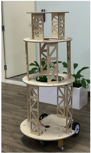
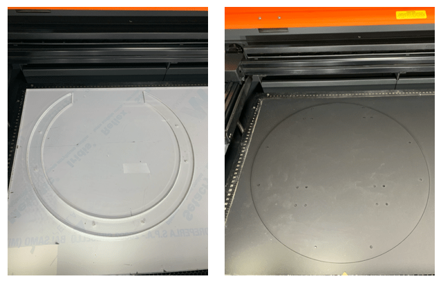
I had milled the inner structure and tablet holder with CNC machine. Additionally, to cover the inner structure of the robot aluminum sheet was used and cut using laser cutter.
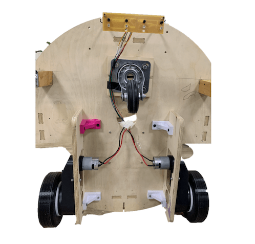
For the electronics the main board I used was ATemga 328p with line following sensor to senes the tracks. Moreover, a DC motor with motor drive used to operate the robot. All the electronics was compound in 3D printed box in the top of the chassis, and the line following sensor was placed in the head of the chassis.
I designed different versions of the robot until I decided which one to choose. I learnt I can design several robots but not all designs can be fabricated. it always important to choose the fabrication technique first then design according to it.
There are around 5 designs for Fab Guide Robot, and most of them were too simple to design, but when we came to the real life it will be difficult to fabricate.
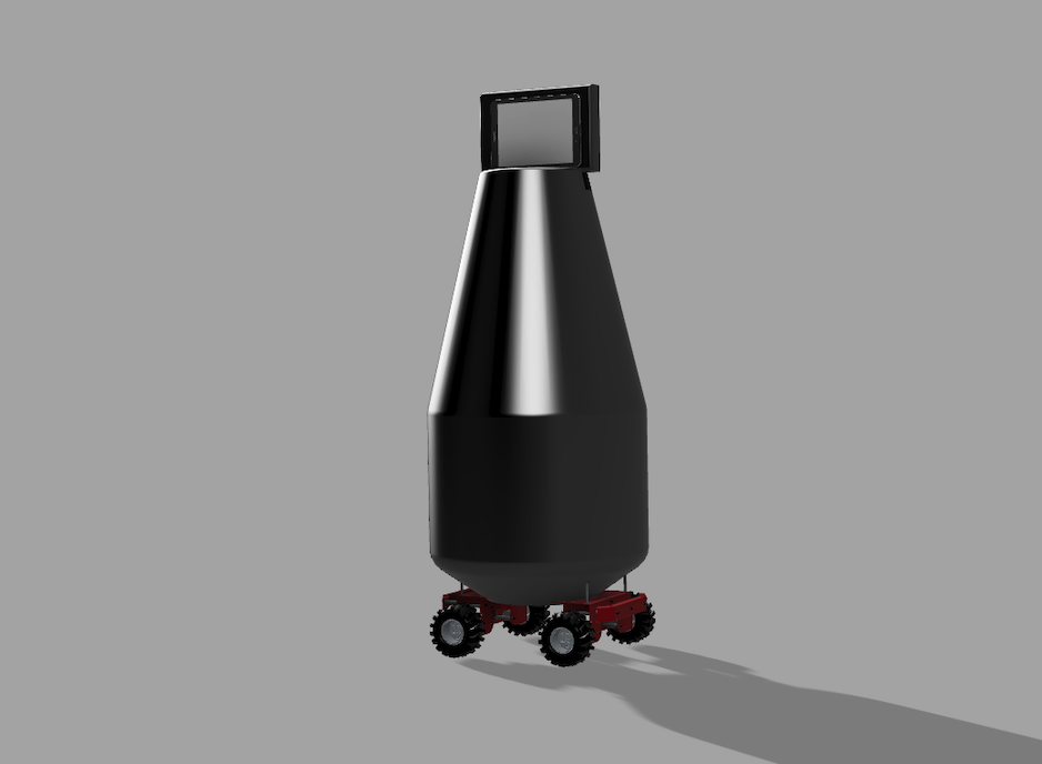
The fifth and the last one was the selected design, the reason of choosing this one for its fabrication capability. There were a lot of developments and improvements on design.
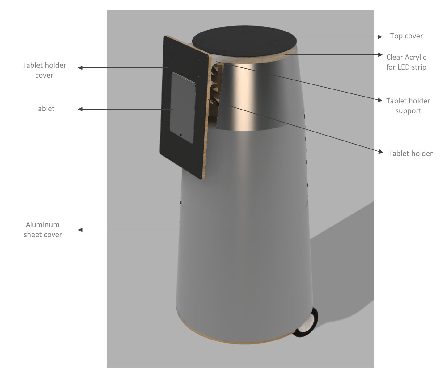
3D model shown the Fab Guide Robot Design
The robot design consist of two main part:
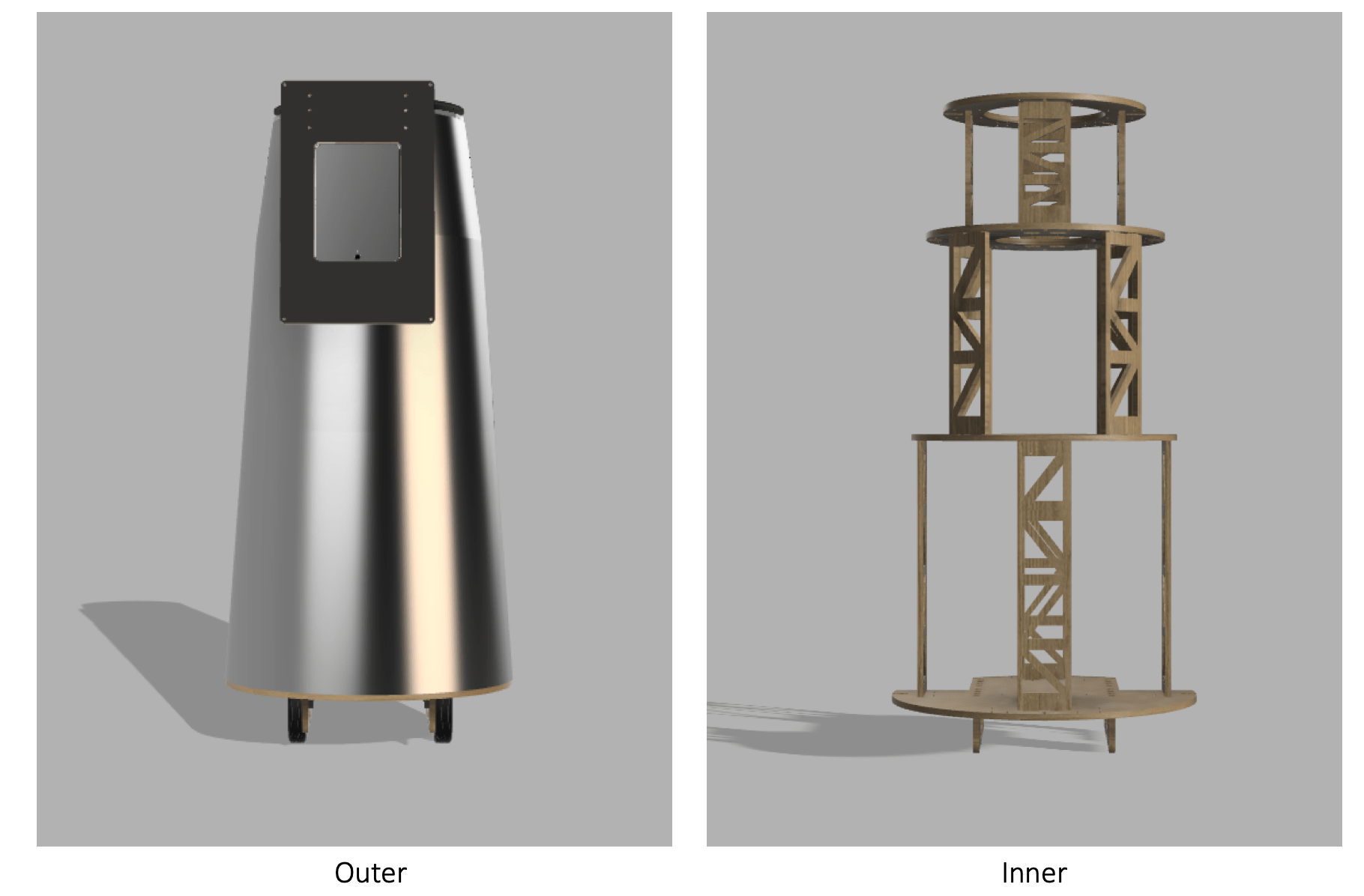
To view the details of the inner structure of the robot visit the computer controlled machining assignment.
For the outer structure I used aluminum sheet to cover the the robot. In fusion 360 design, I measure the center to center distance between the bases to enter them in the in this wonderful website used to create the cone geometry I need and to output the sheets for the fabrication, it will create a cone with truncated.
Next,I need to enter the bases dimeters. Then I saved the files as PDF to prepare them for the fabrication.
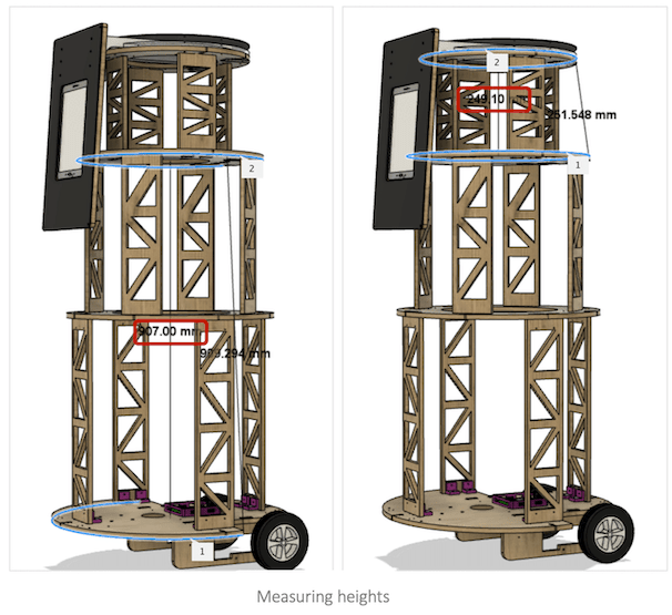
470.624 mm - Base#3600 mm - Chassis907 mm400 mm - Base#4470.624 mm - Base#3249.10 mmAt first, I planned to mill them with shopBot, but there wasn’t enough time, So we outsource the cutting of the sheets using a laser cutter as shown below in the video:
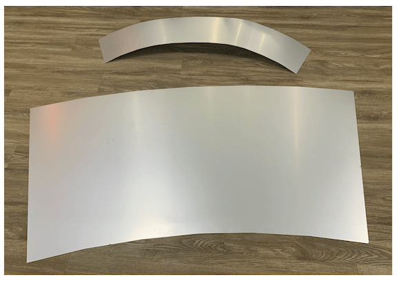
Aluminum sheets
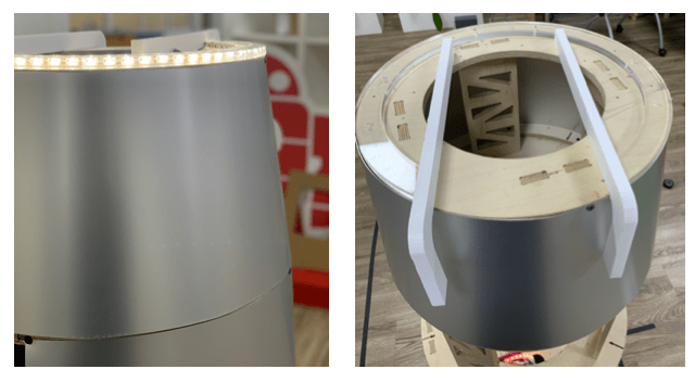
Now is time to pleat and assemble the sheets around the inner structure, by using power 😁, Also for the outer structure assembling, I got help from Ali Many Thanks to his great efforts.
Needed equipment:
The process of assembling was to pleat the sheet first around the structure. we must hold it very well, then we label the screws places and start drilling while Ali was drilling I had to hold the sheets very well. Moreover, we had to were gloves because the ends of the aluminum sheets were so sharp.
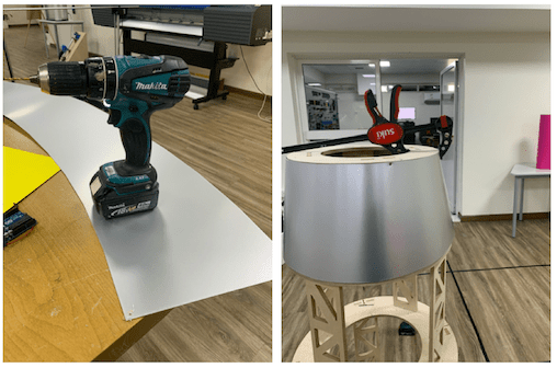
Details!
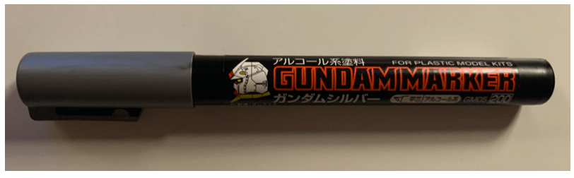
I used black screws. so I used silver paint to hide the black dots.
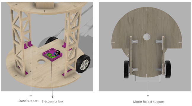
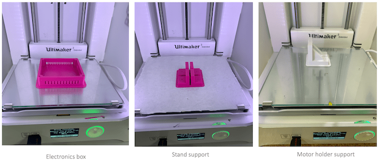
Having stable structure is very important, so I had to design and 3D printing some supports for the motor holder, and stands. Also the electronics box was 3D printed.
Additionally, the Tablet holder and its support was milled with the shopBot. the material of the holder was plywood, but for the Tablet holder support I used HDPE which is very strong which can hold a high load. Moreover, the settings of creating tool-paths for milling HDPE in shopBot is shown below:
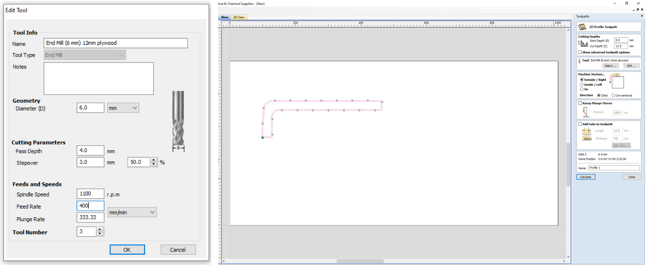
Milling Tablet holder support
Moreover, I used a laser cutter, to cut clear Acrylic 10 mm to place the LED Strip on it to give the robot a beautiful appearance. Also to cover the robot from the top I did cut a circle with matt 3 mm Acrylic, and, I used the same Acrylic to cover the plywood in the tablet holder.
Laser cutting!
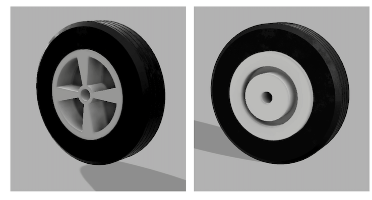
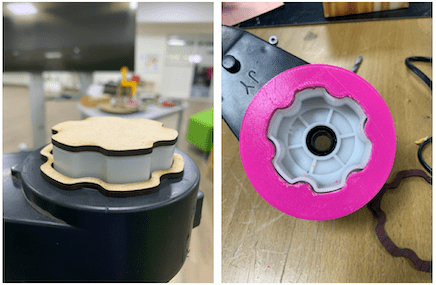
I designed the wheel to be joined to the motor by press-fit the rim into the gearbox of the motor. The wheel design depends on the gearbox used with the motor. As shown below the image of the Electric Reducer Gear Box with DC Motor I used:

The wheel design and fabrication weren’t direct, I had to do several designs and fabrication trials until I came with the best wheel result all the trials will be mention in the Trials and error section.
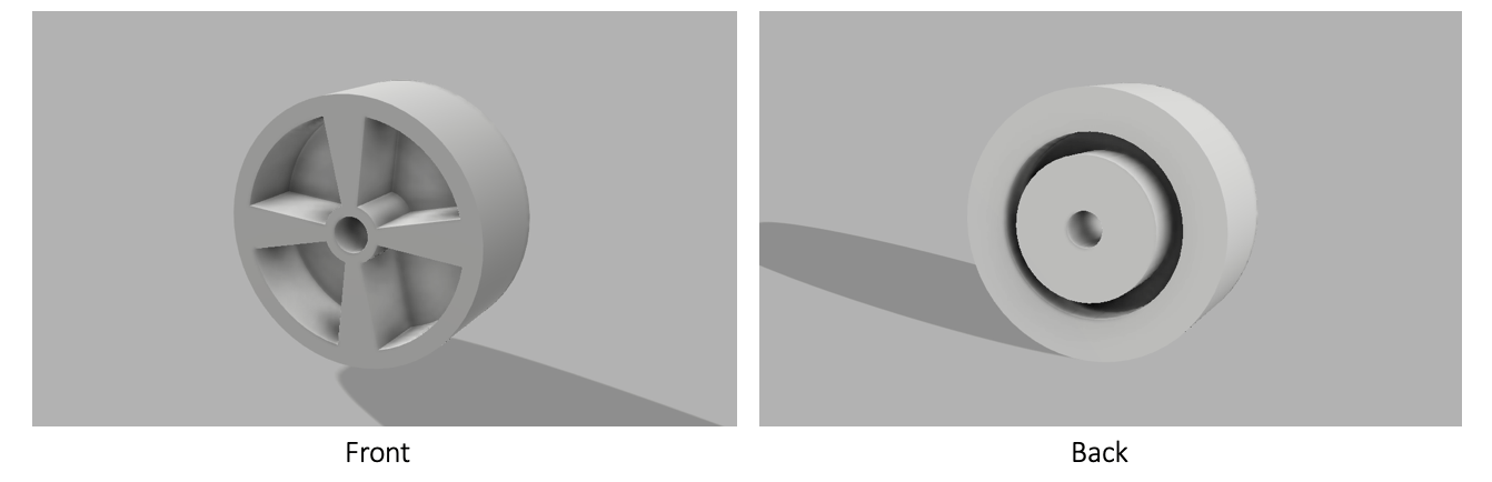
Rim Design
First, I designed the rim to hold the trie, I started by measuring the dimension of the gearbox. Moreover, I found the datasheet of the motor so it was better to get the dimension from it to get the exact shape of the gearbox.
As shown below the final rim design. from the back there is a place to attach the wheel to the gearbox, and, M12 screw bolt will be inserted inside the hole to secure the wheel with the motor from the other side. Additionally, form the front I added some holes in the rim, to make it lighter.
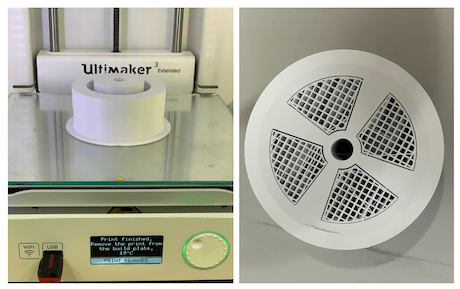
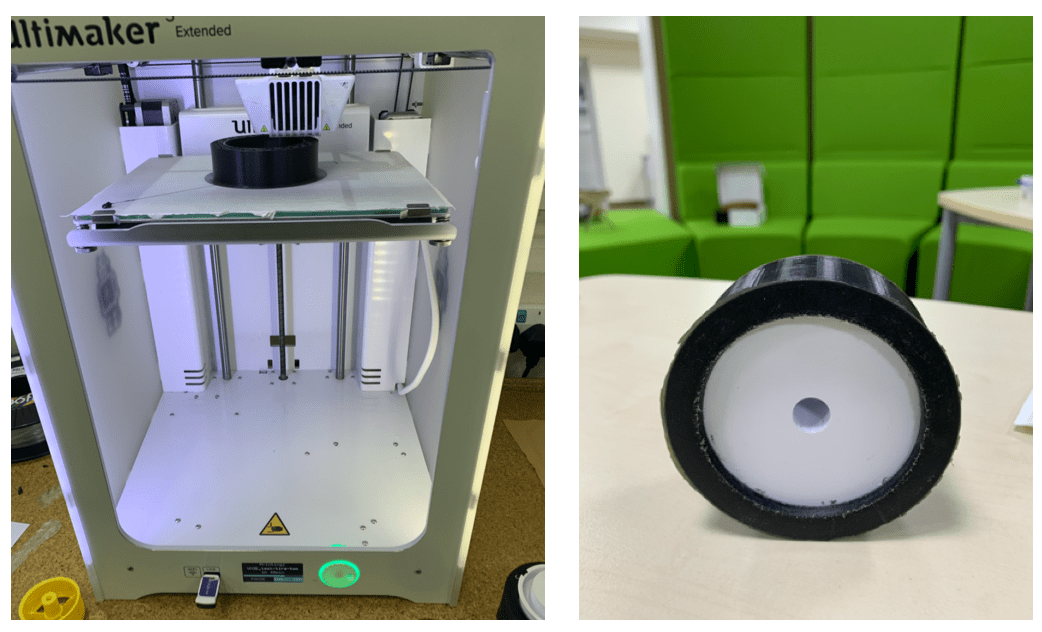
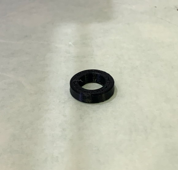
3D printing Rim:
Rim fabrication was direct I used PLA material, also I added support for the printing. However, the printing took a lot of time. One ring needs ~ 10 hours to finish.
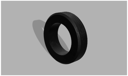
Tire Design
The Tires design is too simple as shown above with a lines pattern on it. To make the Tires more functional and to increase the friction with the ground to have smooth movement.
3D printing Tire:
For the Tire the fabrication process was not direct. I had to use a flexible material for printing. So the printing settings were a little tricky. Moreover, printing flexible material needs some accuracy and patience.
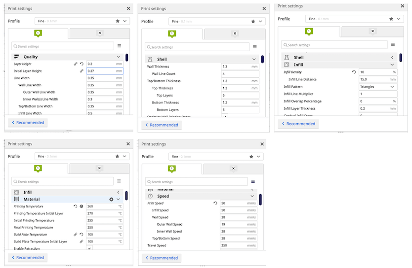
Printing settings:
Used filament: colorfabb NGEN_FLEX filament
I used this link to apply the below settings:
3D printing Tires
Also for the tires, it took around 10 hours to print one tire.
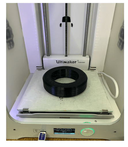
Tire
Tire testing 🤓✌️
As shown below the final wheel design:
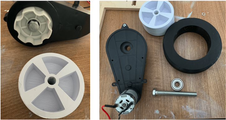
Wheel assembling
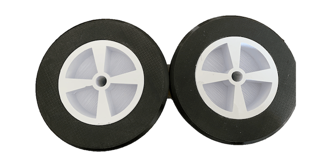
Final wheels
I used a vinyl cutter for cutting the robot tracks,. I drew the lines with the needed width on CorelDraw. Moreover, the sticker type must be matt. Otherwise, the sensor will not detect the line.
Cutting the Tracks
As shown below in the image the arena I made to test the robot in the Lab.
For the main control board, I used the ATemga 328p board produced at electronics design week There were all the input and output pins and controlling features I need in this board, Thus I didn’t have to mill and design another one.
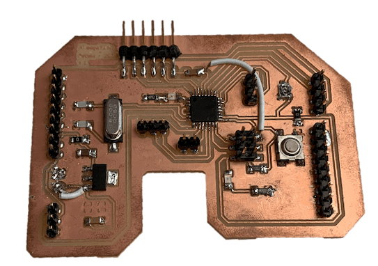
PCB Board
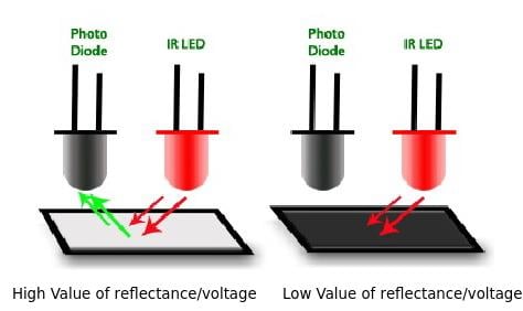
The line following sensor used to detect a black surface on a white or light surface depending on the contrast.
Its usually pairs IR sensor arrays consists of individual IR LEDs (Transmitter) and IR photodiodes (Receiver).
The IR light emitted by the LED hit the surface and is reflected back to the IR photodiode.
The photodiode then gives an output voltage proportional to the reflectance of the surface.
High value 1: White surface.
Low value 0: Black surface.
For PCB design I used this video as reference for the line following sensor array design.
Moreover, I watched and used this YouTube playlist which is about robotics a lot in my project, its helped me a lot in building and programming my robot.
His channel name called Arafa Microsys he has a lot of wonderful courses with simple and easy explanations.
The design consists of 4 pairs of IR LED and Photodiode connected on parallel, then the output will give as the values after detecting the surface White or black.
The distance between the IR LED and Photodiode is not random it depend on the tracks width. I set the distance between each pairs ~ 30 mm as shown in the layout. I used the measure tool in eagle.
Thus, the width of the tracks must be >30 mmif I want the robot to move forward when detecting the white surface. Consequently, the width of the track depends on the code.
Components:
| Qty | Description |
|---|---|
| 4 | Photodiode LED |
| 4 | IR LED |
| 4 | 10 K ohm Resistor |
| 4 | 100 ohm Resistor |
| 1 | 2x3 male Header |
| 1 | LED |
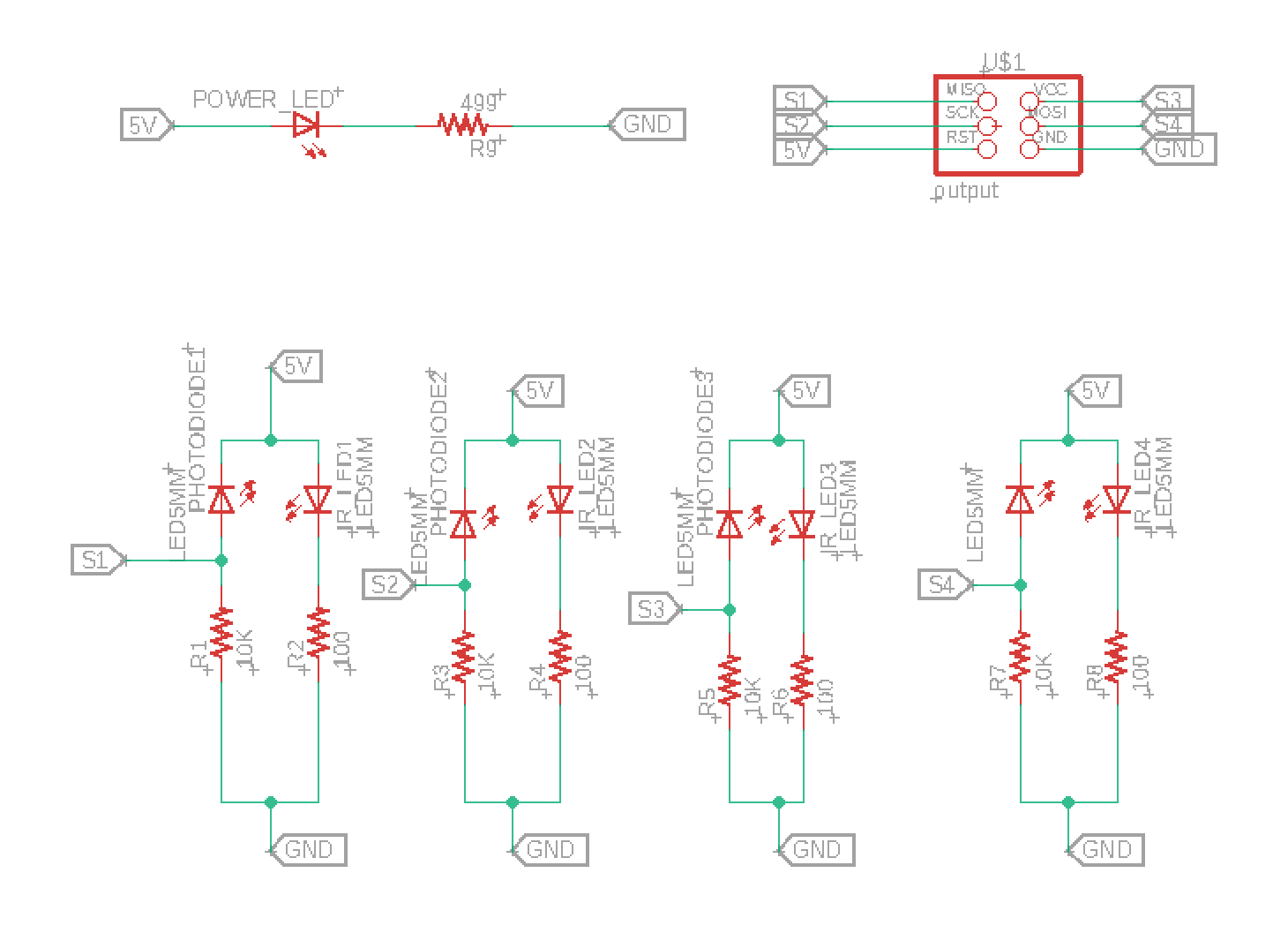
Schematic
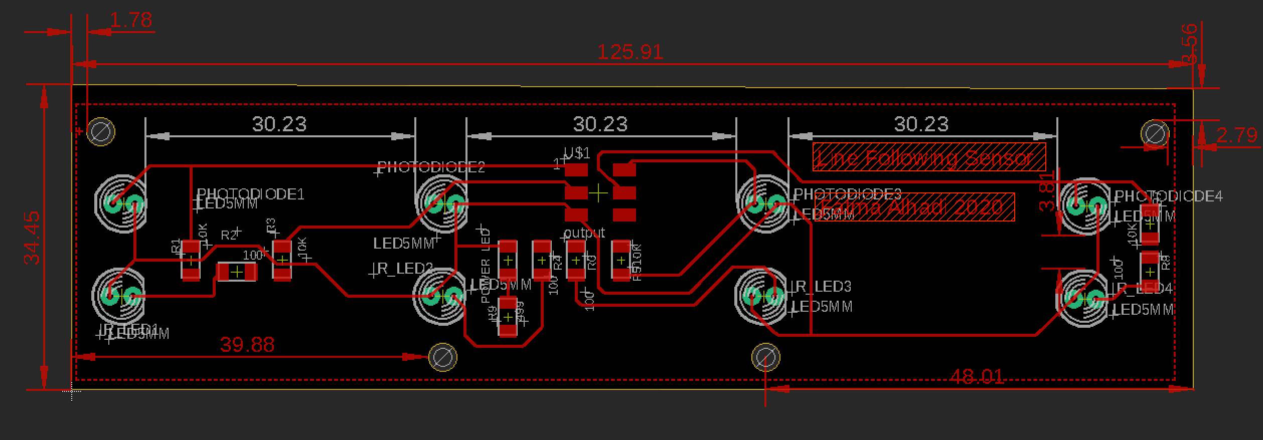
Layout
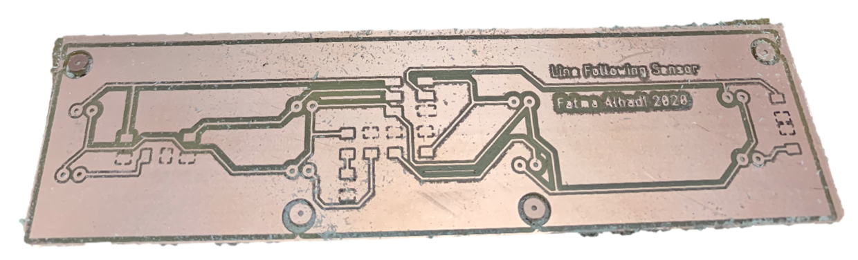
PCB
Soldering
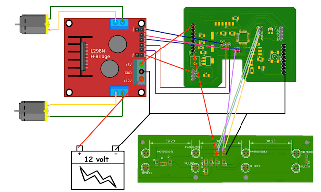
First, connect the DC motors to the L298N H-Bridge board.
Then, connect L298N H-Bridge board to my ATemga 328p board:
The table below shows the connection pins between the boards:
| L298N H-Bridge board pins | ATemga 328p board pins |
|---|---|
| IN1 | PB1 |
| IN2 | PB2 |
| IN3 | PB3(MOSI) |
| IN4 | PB0 |
| ENA | PD5 |
| ENB | PD6 |
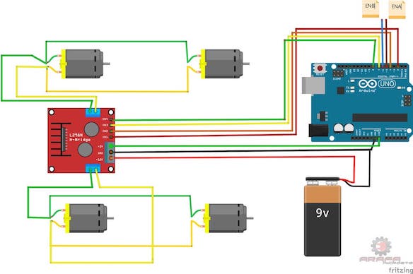
I used the the above Circuit Schematic as reference for the connections, but with taking into consideration the pins I have in my board.
The table below shows the connection pins between the boards:
| Line following sensor | ATemga 328p board pins |
|---|---|
| S1 | PC0 |
| S2 | PC1 |
| S3 | PC2 |
| S4 | PD7 |
LED strip is connected direct to 5V power.
I used 12v Rechargeable lithium ion battery.
As shown below a rough connection diagram for the system. This not the best connection diagram as its so messy😇😊. However, I did the connections quickly on the diagram to simplifies the system.
Before integrates all system parts together, I had test each one separately. First I started with the line following sensor, then I tested the motors. Next, I connected them together on one board and start to program the robot to follow the line, and, disunite between different intersection points, finally, I will develop an application to make wireless communication between the robot and the app using Bluetooth.
Line Tracking Test Code reference:
//#define center 8     //SS3
#define left A1       //ss2
#define right A2      //ss4
#define extleft A0    //ss1
#define extright 7  //ss5
int c,l,r,el,er;//Define variables which used to store digital inputs values
void setup() {
  Serial.begin(9600);
// pinMode(center,INPUT);
  pinMode(left,INPUT);
  pinMode(right,INPUT);
  pinMode(extleft,INPUT);
  pinMode(extright,INPUT);

}

void loop() {
  el=digitalRead(extleft);
  l=digitalRead(left);
  //c=digitalRead(center);
  r=digitalRead(right);
  er=digitalRead(extright);
  Serial.print(el);
  Serial.print("   ");
  Serial.print(l);
  Serial.print("   ");
  //Serial.print(c);
  //Serial.print("   ");
  Serial.print(r);
  Serial.print("   ");
  Serial.print(er);
  Serial.println();
}
The output signal of the sensor array shown in the serial monitor is either 0 or 1. Moreover, the LED starts working indicating there is power in the board.
0 mean black surface.
1 mean white surface.
Test the DC motors with L298N Dual H-Bridge motor drive code reference:
#define in1 2
#define in2 4
#define in3 7
#define in4 8
#define ena 5
#define enb 6

int i=1; //counter for change speed
void setup()
{
  pinMode(in1,OUTPUT);
  pinMode(in2,OUTPUT);
  pinMode(in3,OUTPUT);
  pinMode(in4,OUTPUT);
  pinMode(ena,OUTPUT);
  pinMode(enb,OUTPUT);

}

void loop()
{
  speed1();
  forward();
  delay(5000);
  reverse();
  delay(5000);
  Tright();
  delay(5000);
  Tleft();
  delay(5000);
  off();
  delay(5000);
}
void forward()
{
  digitalWrite(in1,LOW);
  digitalWrite(in2,HIGH);
  digitalWrite(in3,LOW);
  digitalWrite(in4,HIGH);
}

void reverse()
{
  digitalWrite(in1,HIGH);
  digitalWrite(in2,LOW);
  digitalWrite(in3,HIGH);
  digitalWrite(in4,LOW);
}

void Tleft()
{
  digitalWrite(in1,LOW);
  digitalWrite(in2,HIGH);
  digitalWrite(in3,HIGH);
  digitalWrite(in4,LOW);
}

void Tright()
{
  digitalWrite(in1,HIGH);
  digitalWrite(in2,LOW);
  digitalWrite(in3,LOW);
  digitalWrite(in4,HIGH);
}

void off()
{
  digitalWrite(in1,LOW);
  digitalWrite(in2,LOW);
  digitalWrite(in3,LOW);
  digitalWrite(in4,LOW);
}

void speed1()
{
  if(i==5) i=1;
  analogWrite(ena,255);
  analogWrite(enb,255);
  i++;

}
As shown below on the video, this code responsible to move the robot, forward, reverse, turning right, and, turning left. I had to change the speed used in the reference code because each motor differs from the other. The movement of the motors depends a lot on the speed and supplied voltage.
After I make sure the motor drive works well with the motors I have. Now it’s the time to test the robot turning and movement.
The movement and rotation of motors depend on:
Motors - each motor differs and needs to be tested to know which code will do so.
Weight - It depends on the weight the robot carries because the weight will affect the speed and the movement of the robot.
Supply voltage - If the supplied voltage change everything in the code will change, So I have to ensure to have the battery full all time, to get accuracy test for the movements.
Delay on the code
//Created by Arafa Microsys
//www.youtube.com/arafamicrosystems
// Please, don't trade the code without mentioning the source (Arafa Microsystems http://www.youtube.com/arafamicrosystems )
//So as not waste the effort
#define in1 9 //Right motor pole 1
#define in2 10  //Right motor pole 2
#define in3 11  //left motor pole 1
#define in4 8  //left motor pole 1
#define ena 5  //Right motor speed
#define enb 6  //Right motor speed
//#define center 11     //SS3
#define left A1       //ss2
#define right A2      //ss4
#define extleft A0    //ss1
#define extright 7   //ss5

void setup()
{
  //Serial.begin(115200);
  pinMode(in1,OUTPUT);
  pinMode(in2,OUTPUT);
  pinMode(in3,OUTPUT);
  pinMode(in4,OUTPUT);
  pinMode(ena,OUTPUT);
  pinMode(enb,OUTPUT);
  //pinMode(center,INPUT);
  pinMode(left,INPUT);
  pinMode(right,INPUT);
  pinMode(extleft,INPUT);
  pinMode(extright,INPUT);
  analogWrite(ena,255);
  analogWrite(enb,255);
}

void loop()
{ // Turn Right Test, using the dealy, trial and error until reach 90 degree

//  analogWrite(ena,150);
//  analogWrite(enb,170);
//
  analogWrite(ena,200);
  analogWrite(enb,200);
  digitalWrite(in1,HIGH);
  digitalWrite(in2,LOW);
  digitalWrite(in3,HIGH);
  digitalWrite(in4,LOW);
   delay(1000);

  delay(10000);
// off the motors
 digitalWrite(in1,LOW);
  digitalWrite(in2,LOW);
  digitalWrite(in3,LOW);
  digitalWrite(in4,LOW);

  delay(2000);


}
As shown below the turning and movement tests I did for the robot, by trial and error the values until I reach to the best result.
Next, I used the turning test program I did above in this final code were is needed. This code is responsible:
Make the robot follow the line.
Make the robot Go to the desired location depending on the intersection points and his reference location.
//Created by Arafa Microsys
//www.youtube.com/arafamicrosystems
// Please, don't trade the code without mentioning the source (Arafa Microsystems http://www.youtube.com/arafamicrosystems )
//So as not waste the effort
#define in1 9  //Right motor pole 1
#define in2 10  //Right motor pole 2
#define in3 11 //left motor pole 1
#define in4 8  //left motor pole 1
#define ena 5  //Right motor speed
#define enb 6  //Right motor speed
//#define center 11     //SS3
#define left A1       //ss2
#define right A2      //ss4
#define extleft A0    //ss1
#define extright 7   //ss5
//int prev,time1;
//float timeStep = 0.01;
//float yaw = 0;
int l,r,el,er;//Define variables which used to store digital inputs values
int mask=0,mask2=0,mask3=0,mark1=0,mark2=0;
int x=0,y=0,ox=0,oy=0,nx=0,ny=0,pos=0;
int state=0;//orientation state (1=Forward, 2=Reverse, 3=Right, 4=Left)Zero is initial state
void setup()
{
  //Serial.begin(115200);
  pinMode(in1,OUTPUT);
  pinMode(in2,OUTPUT);
  pinMode(in3,OUTPUT);
  pinMode(in4,OUTPUT);
  pinMode(ena,OUTPUT);
  pinMode(enb,OUTPUT);
  //pinMode(center,INPUT);
  pinMode(left,INPUT);
  pinMode(right,INPUT);
  pinMode(extleft,INPUT);
  pinMode(extright,INPUT);
  analogWrite(ena,100);
  analogWrite(enb,100);
}
void loop()
{
  getxy();
  calc();
}

void inertia()
{
  analogWrite(ena,150);
  analogWrite(enb,150);
  digitalWrite(in1,LOW);
  digitalWrite(in2,HIGH);
  digitalWrite(in3,LOW);
  digitalWrite(in4,HIGH);
  delay(100);
}
void forward()
{
  analogWrite(ena,85);
  analogWrite(enb,85);
  digitalWrite(in1,LOW);
  digitalWrite(in2,HIGH);
  digitalWrite(in3,LOW);
  digitalWrite(in4,HIGH);
  //delay(200);
}

void reverse()
{
  digitalWrite(in1,HIGH);
  digitalWrite(in2,LOW);
  digitalWrite(in3,HIGH);
  digitalWrite(in4,LOW);
}

void Tleft()
{
  analogWrite(ena,130);
  analogWrite(enb,110);
  digitalWrite(in1,LOW);
  digitalWrite(in2,HIGH);
  digitalWrite(in3,HIGH);
  digitalWrite(in4,LOW);
  //delay(100);
}
void Tright()
{
  analogWrite(ena,110);
  analogWrite(enb,130);
  digitalWrite(in1,HIGH);
  digitalWrite(in2,LOW);
  digitalWrite(in3,LOW);
  digitalWrite(in4,HIGH);
  //delay(100);
}
void off()
{
  digitalWrite(in1,LOW);
  digitalWrite(in2,LOW);
  digitalWrite(in3,LOW);
  digitalWrite(in4,LOW);
}
void Tleft90()
{
  analogWrite(ena,170);
  analogWrite(enb,170);
  digitalWrite(in1,LOW);
  digitalWrite(in2,HIGH);
  digitalWrite(in3,HIGH);
  digitalWrite(in4,LOW);
  delay(660);
}
void Tright90()
{
    analogWrite(ena,170);
    analogWrite(enb,150);
    digitalWrite(in1,HIGH);
    digitalWrite(in2,LOW);
    digitalWrite(in3,LOW);
    digitalWrite(in4,HIGH);
    delay(660);
}

void Tleft180()
{
  analogWrite(ena,170);
  analogWrite(enb,170);
  digitalWrite(in1,LOW);
  digitalWrite(in2,HIGH);
  digitalWrite(in3,HIGH);
  digitalWrite(in4,LOW);
  delay(1100);
}

void Tright1()
{
  analogWrite(ena,150);
  analogWrite(enb,150);
  digitalWrite(in1,HIGH);
  digitalWrite(in2,LOW);
  digitalWrite(in3,LOW);
  digitalWrite(in4,HIGH);
  //delay(100);
}

void Tleft1()
{
  analogWrite(ena,150);
  analogWrite(enb,150);
  digitalWrite(in1,LOW);
  digitalWrite(in2,HIGH);
  digitalWrite(in3,HIGH);
  digitalWrite(in4,LOW);
  //delay(100);
}
void getvalues()
{
  // If value is equal to 0 means Black and other 1 means White
  el=digitalRead(extleft);
  l=digitalRead(left);
  //c=digitalRead(center);
  r=digitalRead(right);
  er=digitalRead(extright);

}
void compare()
{
    if(el==1&&l==1&&r==1&&er==1)
  {

    if(mask2==0)
    {
      inertia();
      mask2=1;
    }
    forward();
  }
  if(el==1&&l==0&&r==1&&er==1||el==0&&l==1&&r==1&&er==1)
  {
    Tleft();
  }
  if(el==1&&l==1&&r==0&&er==1||el==1&&l==1&&r==1&&er==0)
  {
    Tright();
  }

  if(el==0&&l==0&&r==0&er==0&&mask==0)
  {
     off();
     delay(100);
     mask=1;
     if(y>0&&x<0&&mark1==1||y<0&&x>0&&mark1==1)
     {
      pos--;
     }
     else if(x<0&&y<0&&mark2==1||y<0&&x==0||x<0&&y==0)
     {
      pos--;
     }else pos++;

    //inertia();
    forward();
  }
  if(el==1&&er==1)
  {
    mask=0;
  }
}
void getxy()
{
  nx=-1;
  ny=-1;
}
void calc()
{
  x=nx-ox;
  y=ny-oy;
  if(x>0&&y>0)
  {
    exy();
    state=3;
    orientation();
    exx();
    state=4;
    orientation();
    while(1)
    {
      off();
    }

  }else if(x<0&&y<0)
  {
    mark2=1;
    getvalues();
    state=2;
    orientation();
    exy1();
    state=3;
    orientation();
    exx1();
    state=3;
    orientation();
    mark2=0;
    while(1)
    {
      off();
    }
  }else if(x==0&&y>0)
  {
    getvalues();
    exy();
    while(1)
    {
      off();
    }
  }else if(x==0&&y<0)
  {
    getvalues();
    state=2;
    orientation();
    exy1();
    state=2;
    orientation();
    while(1)
    {
      off();
    }
  }else if(y==0&&x>0)
  {
    getvalues();
    state=3;
    orientation();
    exx();
    state=4;
    orientation();
    while(1)
    {
      off();
    }
  }else if(y==0&&x<0)
  {
    getvalues();
    state=4;
    orientation();
    exx1();
    state=3;
    orientation();
    while(1)
    {
      off();
    }
  }else if(x>0&&y<0)
  {
    getvalues();
    state=3;
    orientation();
    exx();
    state=3;
    orientation();
    mark1=1;
    exy1();
    state=2;
    orientation();
    mark1=0;
    while(1)
    {
      off();
    }
  }else if(x<0&&y>0)
  {
    getvalues();
    exy();
    state=4;
    orientation();
    mark1=1;
    exx1();
    state=3;
    orientation();
    mark1=0;
    while(1)
    {
      off();
    }
  }

}

void orientation()
{
  if (state==2)
  {//reverse Orientation
    Tleft180();
    off();
    state=0;
  }else if(state==3)
  {
    //inertia();
    Tright90();
    off();
    state=0;
  }else if(state==4)
  {
    inertia();
    Tleft90();
    off();
    state=0;
  }
}

void exy()
{
  loop7:
  if(y>pos)
  {
    getvalues();
    compare();
  }else if(y==pos)
  {
    off();
    pos=0;
    goto loop8;
  }
  goto loop7;
  loop8:
  pos=0;
}

void exx()
{
  loop9:
  if(x>pos)
  {
    getvalues();
    compare();
  }else if(x==pos)
  {
    off();
    pos=0;
    goto loop10;
  }
  goto loop9;
  loop10:
  pos=0;
}

void exy1()
{
  loop7:
  if(y<pos)
  {
    getvalues();
    compare();
  }else if(y==pos)
  {
    off();
    pos=0;
    goto loop8;
  }
  goto loop7;
  loop8:
  pos=0;
}

void exx1()
{
  loop9:
  if(x<pos)
  {
    getvalues();
    compare();
  }else if(x==pos)
  {
    off();
    pos=0;
    goto loop10;
  }
  goto loop9;
  loop10:
  pos=0;
}
Final code test video:
I was struggling to make the robot to follow the track, with the above code so I tried a different code, and it worked. But still not following the line properly as shown in the video below. He goes in/out of the path, and sometimes he follow the line and sometimes he didnt. I planning to improve the code by using PID control to ensure the stabilty of the robot while following.
/*Mert Arduino and Raspberry Pi - Line Following Robot*/

//Define Pins

int ENA = 5; //Enable Pin of the Right Motor (must be PWM)
int IN1 = 9; //Control Pin
int IN2 = 10;

int ENB = 6; //Enable Pin of the Left Motor (must be PWM)
int IN3 = 11;
int IN4 = 8;

//Speed of the Motors
#define ENASpeed 150
#define ENBSpeed 120

int Sensor1 = 0;
int Sensor2 = 0;
int Sensor3 = 0;
int Sensor4 = 0;

void setup() {

  pinMode(ENA, OUTPUT);
  pinMode(IN1, OUTPUT);
  pinMode(IN2, OUTPUT);

  pinMode(ENB, OUTPUT);
  pinMode(IN3, OUTPUT);
  pinMode(IN4, OUTPUT);

  pinMode(Sensor1, INPUT);
  pinMode(Sensor2, INPUT);
  pinMode(Sensor3, INPUT);
  pinMode(Sensor4, INPUT);

}

void loop(){

  //Use analogWrite to run motor at adjusted speed
  analogWrite(ENA, ENASpeed);
  analogWrite(ENB, ENBSpeed);

  //Read the Sensor if HIGH (BLACK Line) or LOW (WHITE Line)
  Sensor1 = digitalRead(A0);
  Sensor2 = digitalRead(A1);
  Sensor3 = digitalRead(A2);
  Sensor4 = digitalRead(7);

  //Set conditions for FORWARD, LEFT and RIGHT

  if(Sensor4 == HIGH && Sensor3 == HIGH && Sensor2 == LOW && Sensor1 == LOW){

    //Turn LEFT
    //motor A Backward
    digitalWrite(IN1, LOW);
    digitalWrite(IN2, HIGH);

    //motor B Forward
    digitalWrite(IN3, HIGH);
    digitalWrite(IN4, LOW);
  }

  else if (Sensor4 == LOW && Sensor3 == LOW && Sensor2 == HIGH && Sensor1 == HIGH){

    //Turn RIGHT
    //motor A Forward
    digitalWrite(IN1, HIGH);
    digitalWrite(IN2, LOW);

    //motor B Backward
    digitalWrite(IN3, LOW);
    digitalWrite(IN4, HIGH);
  }

  else{

    //if(Sensor4 == LOW && Sensor3 == HIGH && Sensor2 == HIGH && Sensor1 == LOW

    //FORWARD
    digitalWrite(IN1, HIGH);
    digitalWrite(IN2, LOW);
    digitalWrite(IN3, HIGH);
    digitalWrite(IN4, LOW);
  }
}
Results and discussion:
I had noticed whenever the battery not fully charge or when I tested with chassis or with the entire body I get different results. So, in the future, I plan to test the robot with a better battery with high capacity and longer charging time of the battery. Moreover, the testing must be with all robot parts so the weight will not affect the code. The robot follows the line, what left is to make him define the different intersection points and connect him with the app to control him.
Steps:
Create Account on MIT App Inventor.
Download MIT app in the Tablet.
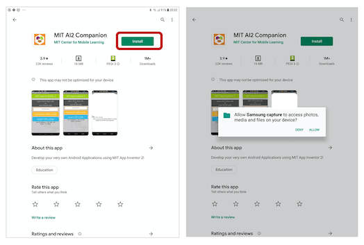
Connect the application with the tablet through Bluetooth.
The app is ready to use.
Testing bluetooth model:
As shown in the video below:
Code:
#include <softwareserial.h>


SoftwareSerial BT(10, 11); //TX, RX respetively
String state;// string to store incoming message from bluetooth


void setup() {
 BT.begin(9600);// bluetooth serial communication will happen on pin 10 and 11
 Serial.begin(9600); // serial communication to check the data on serial monitor
  pinMode(13, OUTPUT); // LED connected to 13th pin


}
//-----------------------------------------------------------------------//
void loop() {
  while (BT.available()){  //Check if there is an available byte to read
  delay(10); //Delay added to make thing stable
  char c = BT.read(); //Conduct a serial read
  state += c; //build the string- either "On" or "off"
  }
  if (state.length() > 0) {
    Serial.println(state);


  if(state == "turn on")
  {
    digitalWrite(13, HIGH);

      }

  else if(state == "turn off")
  {
    digitalWrite(13, LOW);
     }


state ="";}} //Reset the variable


</softwareserial.h>
Developing user interface:
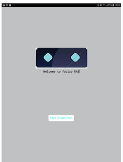
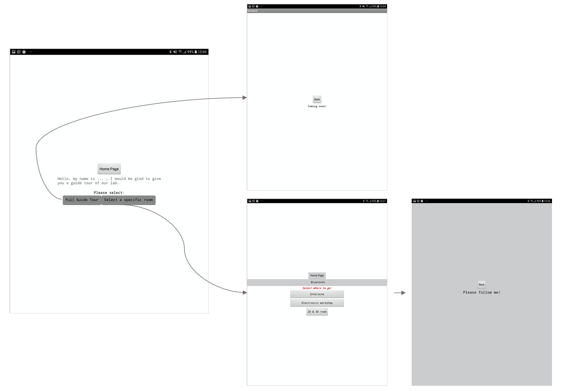
As shown from the below images and video, I had finish develop the first user interface design. what left is connect each button of the app to the robot.
First to start and operate the robot press the start guide tour button. This button responsible to turn on the robot.
Second, as shown there are two choices: To have a full guide tour of the lab: the robot will demonstrate the entire Fablab for the visitors and explains all the actives. this section is still under development. The second choice is to select a room for you are interested to know her actives. Finally, press on back to take the robot back to his home point which is Fablab reception.
Application Video
Fab Guide Robot
This selection will include all the problems I had and how I did troubleshoot them. In addition to the future opportunities I may add in my project.
As shown below I designed several versions robots until I decided which one to fabricate.
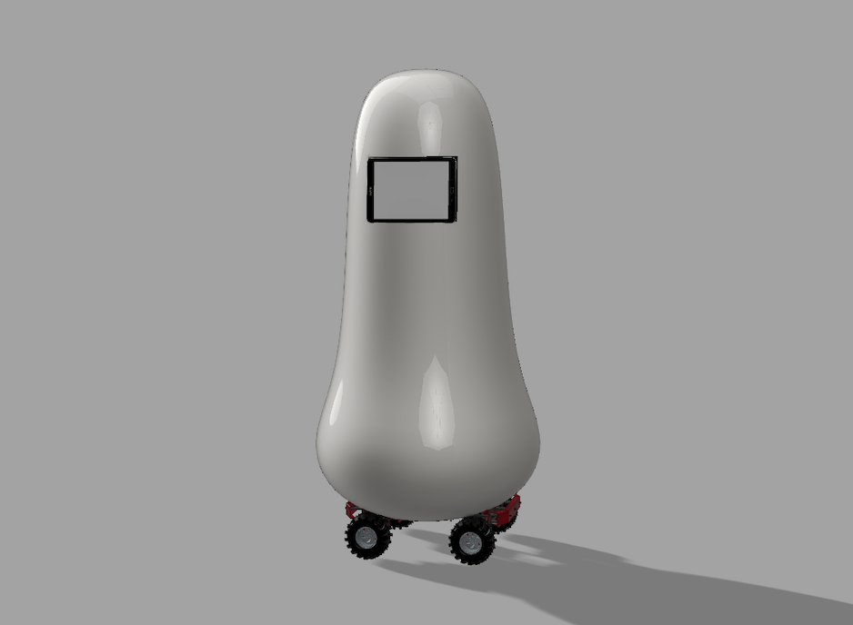
Fab Guide Robot V1
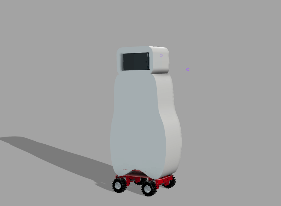
Fab Guide Robot V2
Fab Guide Robot V3
Fab Guide Robot V4
MDF using a laser cutter, to check if the dimensions were correct. Also, I had to test part using 3D printing as the values will differ. As in the end, I will print the rim using 3D printing. it was really difficult to set the exact values and shape, so I shift to another idea, the rim will be press fit but not have to be the same shape. it will be a circle with a diameter will hold the gearbox very well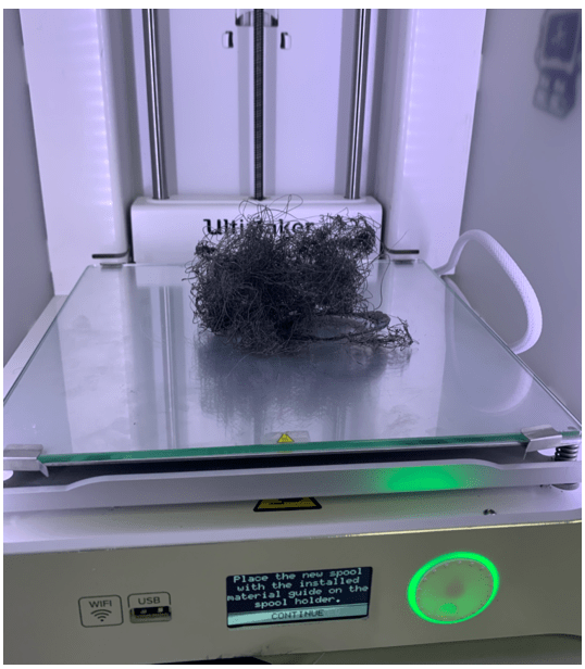
I entered wrong settings in the next printing I used the correct settings mentioned in the Tire section above.
I entered the wrong settings for the printing, in the next printing I used the correct settings mentioned in the Tire section above.
Final Tire Scaled
I did a lot of trials to produce the Line following sensor. I milled the sensor 4 times until everything was fine.
Even Though this board has too simple, it took a lot of time to have perfect. This Fab Academy having weird and unexpected problems are normal. but At the same time, learning new things every day, this why I loved this diploma.
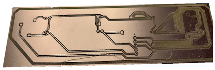
The first milling:
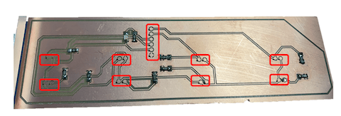
The second milling:
When I had to change the milling bit from 1/64 to 1/32 to drill the holes and cut the outline, I Changed the XY origin points and set an new one by mistake.
Thus, I tried my best to set the XY point in the old the same old origin.
For the outline everything was fine, but for the holes, it wasn’t in the middle of the pads. none of the traces get damaged, but if I will solder the components they will be shorted with the ground. Thus, I tried to make manual drilling , and didn’t work the problem was the pad too small and thin so when I try to drill the pad removed from the board, I had to mill the third board.
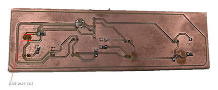
The third mill:
I did some modifications to the PCB design. The milling was fine, I was happy and soldered all components and ready to test the sensor. However, While testing I figure out that I reversed between the IR and photodiode, so I had to de-solder all of them, and something unexpected happens all the pads and traces were cut!
And it was Thursday, so I did not have any time to mill another board so I tried my best to fix it at home at the weekend but it was impossible.
I came to the lab on Saturday to mill the fourth and the last board for the sensor.
I soldered the board in the home, but one of the photodiodes was not aligned right with the board so after soldering the traces and pad cut, so I had to add wires to fix the connections.
last updated: 11/01/2020
What parts worked in my project?
What parts didn't work?
Problems & challenges + My future plans to solve them:
Using a different battery. To be more suitable for the robot requirements.
Test the robot with its whole weight to ensure the code works correctly.
Use PID control for line Following sensor to get stable movements for the robot.
To attach the line following sensor to the chassis in a better way.
I will design a part to hold the line following sensor very well to protect the sensor. Moreover, I will measure the distance carefully, and consider it in the design.
on/off the robot from the battery. The process of testing the was exhausting sometimes because I need to pull the battery quickly from the robot before he hit something.I want to take this chance to thanks Hamdan Bin Rashid Al Maktoum Center for giftedness and innovation and Fablab UAE for offering this wonderful opportunity to us. Moreover, I would like to express my gratitude and appreciation to our instructor Hashim Alsakkaf for his guidance, continuous encouragement, and support during Fab Academy. My thanks are also extended to my collogues for their continuous help and motivation, they made my journey in Fab Academy very special. Fab Academy was one of the best experiences I had in my life. Furthermore, I would like to extend a special thanks to All Fab Lab UAE Engineers and staff for their help and support during our study.
