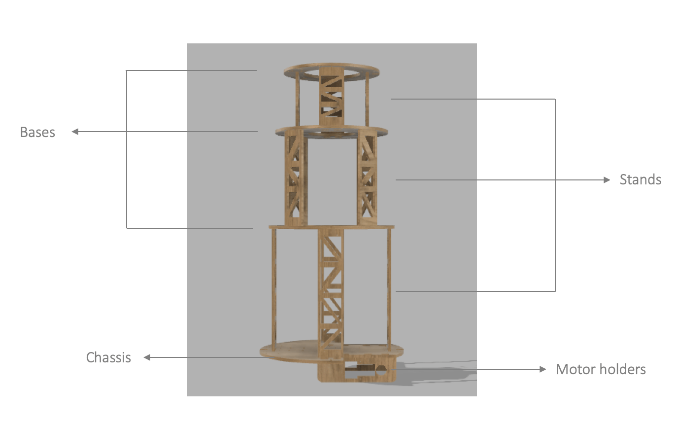
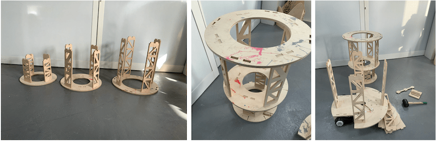
Robot inner structure with labeling parts
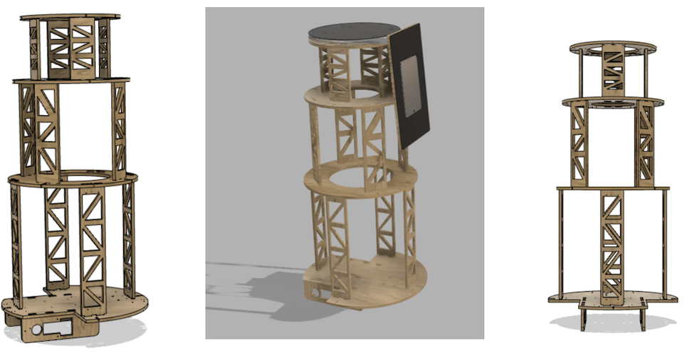
Different views of the structure
Group assignment: To view the tests for our machine ShopBot please visit the group page.
Documented how you designed your object (something big)
Documented how you made your CAM-toolpath
Described problems and how you fixed them
Included your design files and ‘hero shot’ photos of final object
The chassis and the inner structure of the Fab Guide Robot was fabricated using CNC milling, which is my final project.
I spent a lot of time designing, as I don’t have enough experience with designing. Moreover I wanted ensure to have a stable design, also there were a lot of details I must take in consideration such as electronics place, wheels places, line following sensor, support holes, Aluminum slots places, motor holder place, stands, Tablet holder, and, some extra holes for fixing extra parts if needed.
Many thanks to our instructor Hashim he helped me a lot in the designing process. Additionally, he taught me a lot of techniques helped in improving my designing skills.
Before designing the robot structure, I was a big noob in designing 🤓😆. However, now my skills had improved I can design better than before ✌️
First, to design the robot structure, I browsed a lot of ideas on the internet for different guide robot designs. Moreover, I set some features I want to have in the robot:
Suitable length for kids and adults.
Place to put the Tablet.
Fabrication capability
Stability.
I did several designs until I set on this design. This was one of the hardest choices in the project, to select the best design, that can capability to be fabricated in Fab Lab.
One of the important points to have is a stable design, I did not want to build robot that will fall down on people 🏃.
So I worked a lot on this point with our instructor. Any change I did in the design must be taken into consideration, whether this change will affects the stability of the structure or not. Moreover, it was better if I did a stability study for structure but there was not enough time, so we relied on experience and luck.
The most thing I was scared of it, is when we will assemble the robot it will fall down. Fortunately, the robot was stable
In this assignment I will discuss, the inner structure of the robot, and the milling process was not direct I had to mill the chassis and motor holder a few times until I reached the perfect one.
One of reasons I designed a big robot because of the height, and, I want to experience building a big robot. In fact now a days whenever you build something smaller it is better, but I wanted to try.
I used Fusion 360 for the designing. When the 3D model is finished, I created sketch on the surface , and project the 2D face of the wanted body to mill it. Afterward I saved it as a DXF file.
Joint and Slots:
Material thickness = 12 mm Plywood.
Kerf= 0.2 mm
t = thickness = 12 mm
(t-kerf) = 11.8 mm
I started milling using the joint test my colleagues has done before me, so I skipped the test. It was known if I will use a wood sheet with 12 mm thickness the kerf = 0.2 mm. I edited my design according to this value.
Robot inner structure with labeling parts
Different views of the structure
As shown above, in the 3D model of the robot. The motor holder was attached to the chassis with needed slots according to the gearbox design, and it had the necessary holes to do the electrical connections. In addition, the size of the bases starts to reduce from the bottom to the top, to have a stable structure. Moreover, a holes were added in the stands to reduce the robot’s weight.
Opening Vcarve Software.
Select create a new file. Next a new job setup page will pop up.
Enter the below setting as shown :
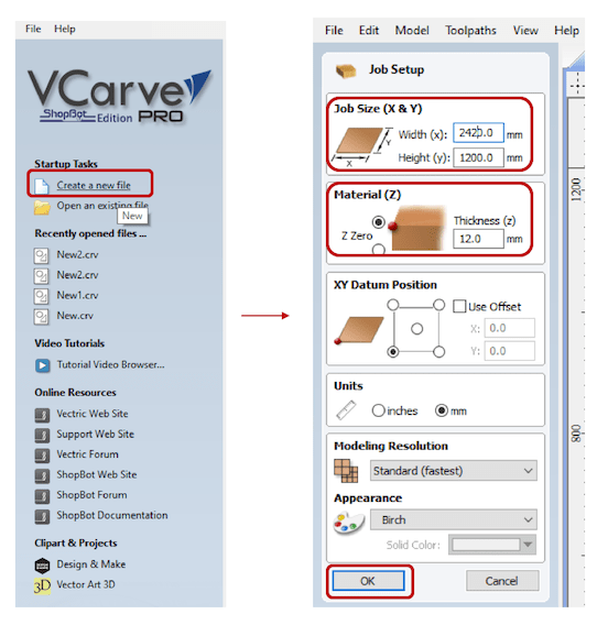
1. Setting Job Size (X & Y):
Sheet dimensions X(Width): 2420 cm and Y(Hight): 1200 cm, The original size of sheet is 2440 X 1220 cm, But I enter it smallest by 20 cm to ensure the tool will not hit the screws, because it’s may lead to risk.
2. Material (Z): Enter the sheet thickness = 12 mm, Enter: OK
Note: I did the milling in separate days, so every time I changed the sheet size according to the available area in the working space to ensure the end-mill will not hit the fixing screws and to use the space in an efficient way to prevent material waste.
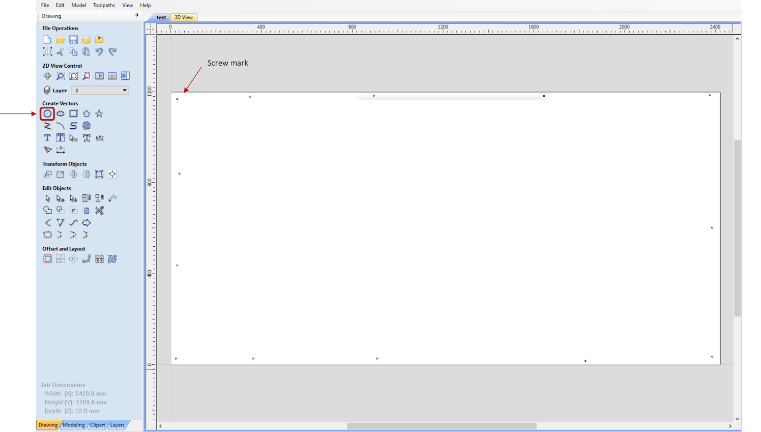
Now the workspace is ready for importing designs. But, before importing the pieces and arrange them, is better to start by labeling the fixing screws places by using Drilling Toolpath.
I placed circles with 6 mm dimeter and place them all around the sheet edges as shown below:
Select all the circles (screw marks).
Select Tool-path Operations
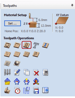
Cut depth: 1.5 mm because I need only to mark the places of screws, then we will do manual drilling.
Select tool: End mill 6mm
Calculate.
Save tool-path(s) to file.
This tool path saved and ready to be output in the shopBot.
Afterward, I will be explaining in sections below how to operate the ShopBot.
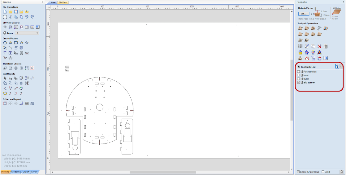
Vcarve, Go to File> Import>Import vectors: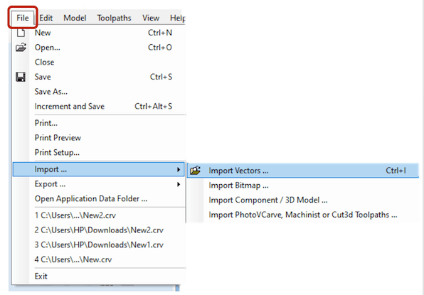
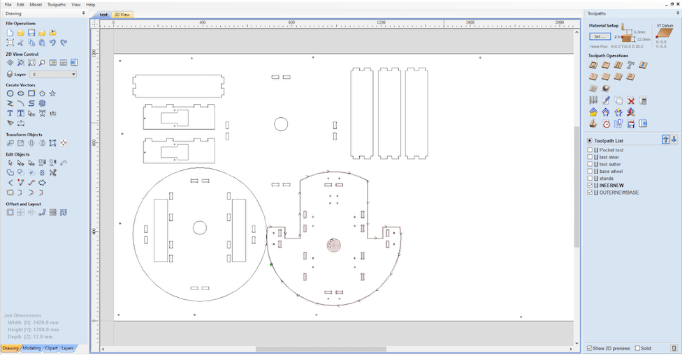
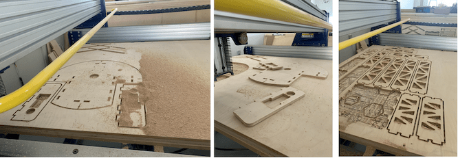
The first milling: was test for the chassis, motor holder, and, the slots.
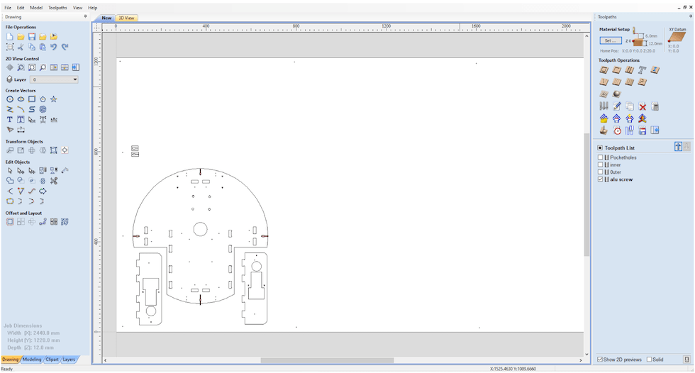
The second milling: was the updated chassis and motor holder.
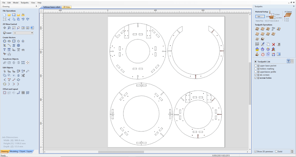
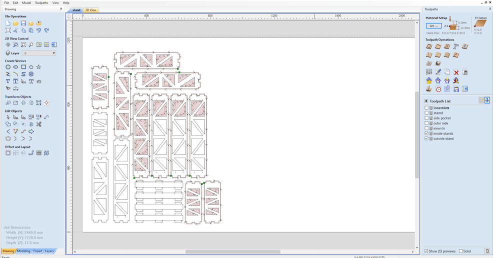
The Third milling: was the bases and first layer of the stand to test them.
Each time the process of creating toolpaths was the same, except in chassis, motor holder, and, bases, I used different endmill’s 6mm for cutting and 3mm for the holes and Aluminum slots.
As shown below the setting for the Tools:
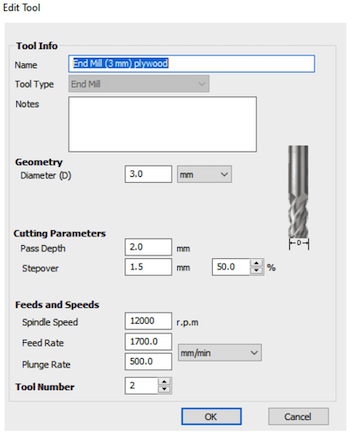
End-mill 3mm
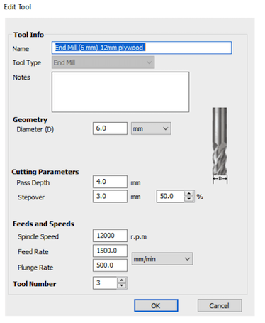
6mm
The process was:
Arrange the parts.
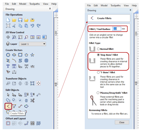
Create DogBones in inside all the slots edges (corners).
To create DogBones:
Go to Edit object > create filet > dogBone
6mm:
3 mm.3mm:
1.5 mm.I used DogBones so joints press-fit into each other perfectly, Otherwise to will be hard to assemble the parts.
Always in milling we cut the inner parts first, then the outer parts.
Drilling toolpath Used to fix the screws.
Pocket toolpath. Inner cut
Profile toolpath. Outline/outer cut and cutting in general.
Note: As the process of creating tool-path for the shopBot milling the same. So I will explain the used settings on chassis and motor holders milling only, and the process will go the same for other parts taking into consideration the used tools and different settings.
First I start by creating the pocket toolpath to cut the inner parts, so I select all part I want it cut inside then select the icon of pocket toolpath
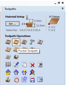
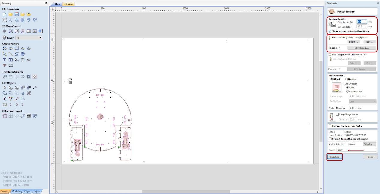
Select:
Cut depth: 12.5 mm. we always increase the cutting depth by 0.5 mm. because we want the tool to cut through out the material.
Tool: End Mill 6mm Plywood.
Name the tool path, to save it as .sbp file.
Calculate.
Then the toolpath now is added to the tool-path list. which can be selected and saved after for milling.
Next, as there some details in the design needed to be done using end mill 3mm tool I will create different tool path for inner pieces that need to but cut with 3 mm end mill and save separately.
I will create for:
The Aluminum slot and as I don’t want the tool to cut through out until the end, I will select the cut depth = 10 mm.
The holes as shown below the settings for both toolpaths::
Aluminum slot:
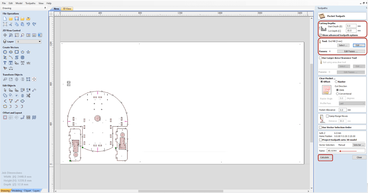
Holes:

In the Profile Toolpath I will select the outline of the part to cut them.
As shown below the settings for Profile Toolpath:
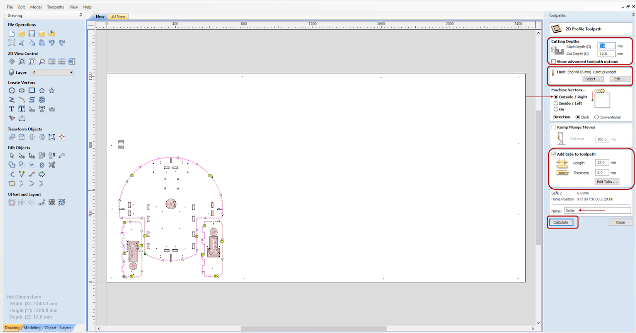
Cut depth: 12.5 mm
Tool: End Mill 6mm Plywood.
Machine vectors: Select outside/right
Here we select if we want the cut on the line or outside the line or inside the line.
Check Add tabs to toolpath, I used tabs to ensure the parts will stay in it place while milling.
Name the tool path.
Calculate.
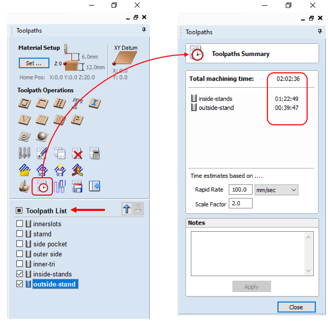
Prepares files for cutting:
The Tool-path list shown all available tool-paths to select them for milling. Moreover, to view the total machining time I click in the icon as shown below:
In addition, to post processor files > save the tool-path to be used afterward in ShopBot sb3 software as shown below:
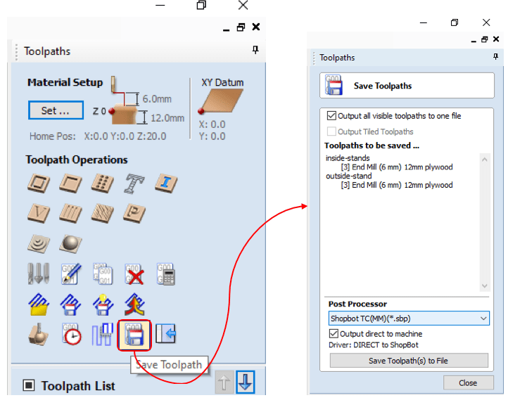
Next, to start milling tick the boxes of the wanted tool-paths in the tool-path list, the machine will start milling from top to bottom ticked tool-paths.

Summary milling steps:
Set zeros.
Cut parts.
Clean the sheet.
Remove parts.
Sanding.
Assemble.
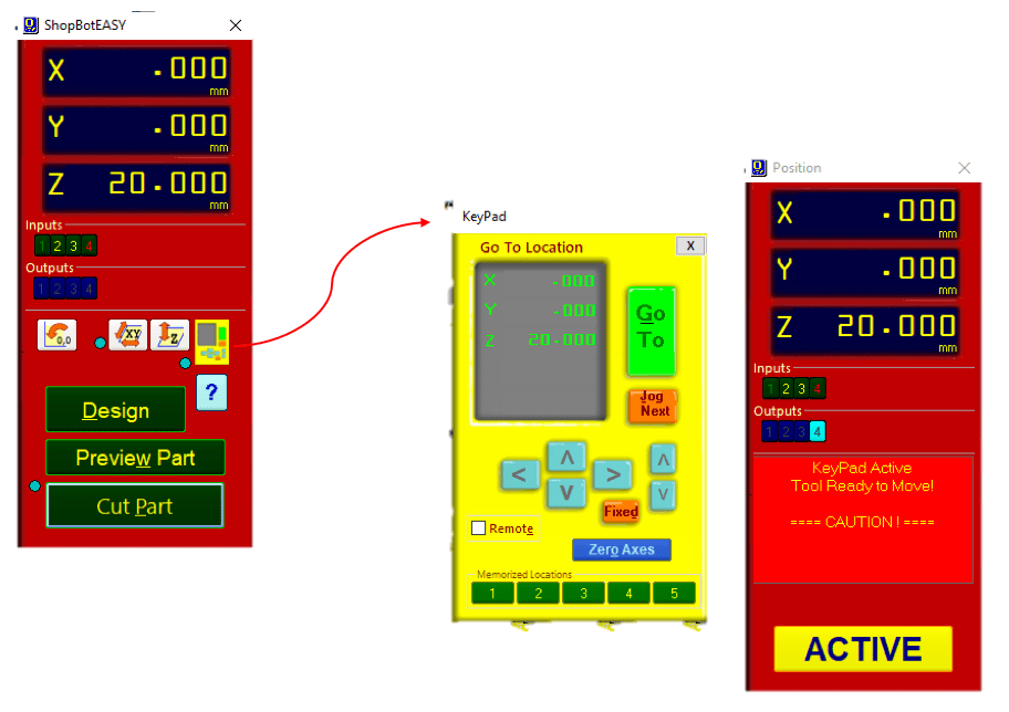
To move and give orders in ShopBot we use: 1. Control panel. 2. KeyPad.
| Control panel | KeyPad |
|---|---|
| Provides main machine information and controls | Used to manually move the X,Y, and, Z axes |
| used to move the router to set XYZ axes | moving the spindle and XY axes by using the blue arrows. |
| Giving order of cutting parts | - |
To open the KeyPad, by clicking the yellow box in the control panel:
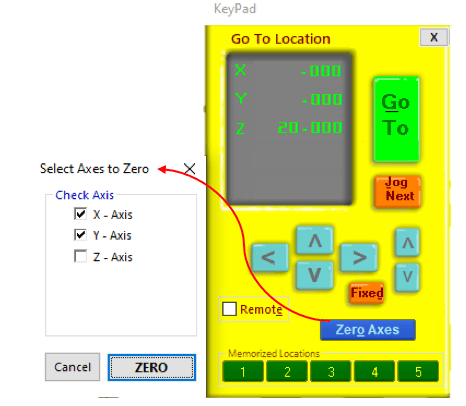
First thing to do is setting zero of X- and Y-axes , the shopBot it self has its own zeroes points. the machine will move until hitting the limit switch for X and Y this process called proximity switch homing process. which creates an accurate and repeatable start point.
Manually, I moved the XY axis for the wanted place in the sheet, Then I selected my own zeros of X and Y from KeyPad as shown:
The Z-axis must be zeroed each time that the machine is turned On or bits are changed. The process of setting the zero for Z axes done automatically. First, I move the tool to empty place, where is no holes or anything, and take the router up.
Next, using the metal plate, by put it under the bit, then from the software I click set zero, the Z axis will go down to touch the plate for three times. This operation will set the Z to zero.
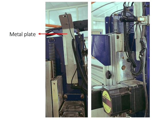
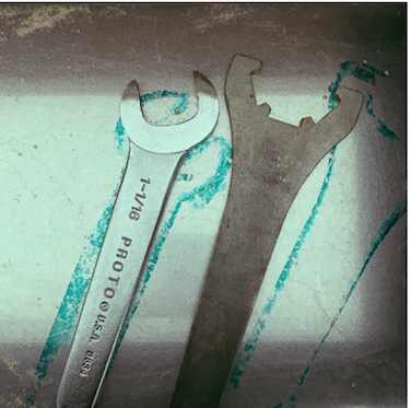
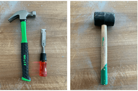
I used two tools for milling the design. Thus, I had to change the tool bits. For changing the tool I need to use these two wrench shown below in the image, this wrench is connected to the key with shopBot for safety reasons. So the machine will turn off while changing the tool, to avoid any unaccepted moves from the machine.
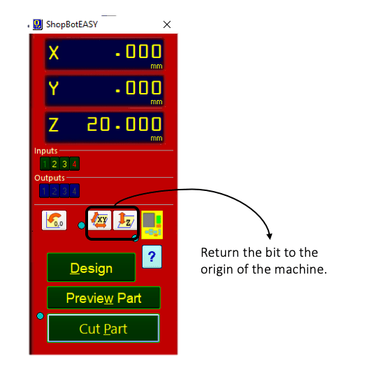
Now the zeros is set up to the origin points. I can start cutting the parts.
They are two ways to start milling:
Cut Part at control panel as shown below: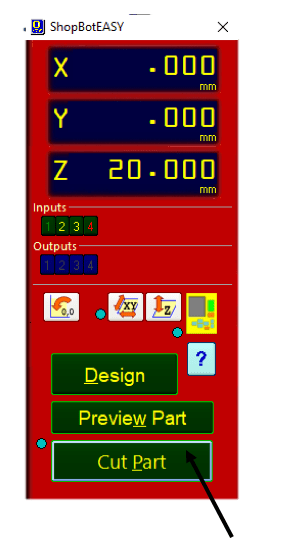
clicking on cut part will start milling for the tool-paths selected Before in the tool-paths list.
After clicking on the cut part some warnings will pop out, we had to read and follow the instruction.
Finally to start milling click on start at the remote control.
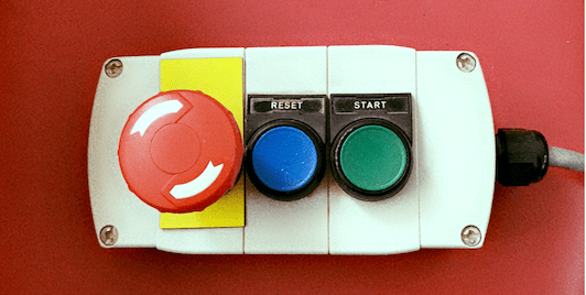
Additionally, for safety reasons I must monitor the shopBot while milling all the time. and I must to keep the remote control near to me in case I need to stop the machine using the emergency switch, also I had to stay outside the milling room and close the door as the filtration not working and for safety reasons.
However, if I stayed inside the room while milling I must stand in the extra right edge of the machine.
As filtration was not working, I had to clean the wood chips from sheet manually using Vacuum cleaner. Afterward, to remove the parts from the sheets and break the tabs I used the equipments shown below:
Next, I did sanding the parts, with the help from Ali and Armn. Many thanks to them.
Before explaining the assembling process, this section needed a lot of physical strength and mechanical experience. Thus, Ali helped me a lot in the Assembling, Thanks to his help I finished quickly. We did started assembling from bottom to top.
Some of the problems I noticed after milling were:
I solved these problems gradually until the fourth milling.
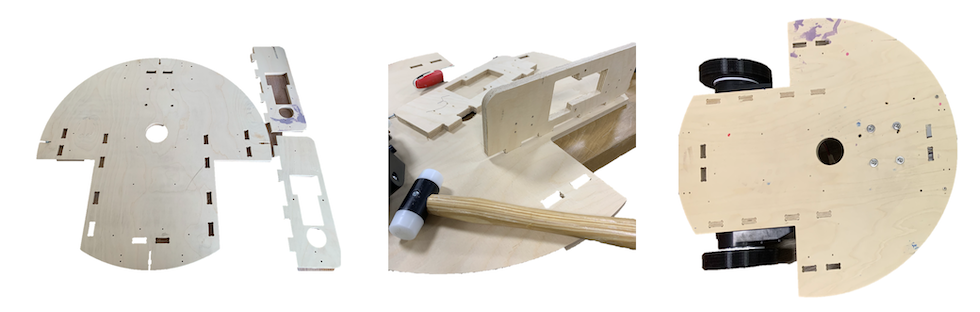
Chassis & motor holder.
I used Box Beam Level, to ensure the chassis leveled correctly.
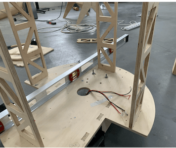
Bases and stands.
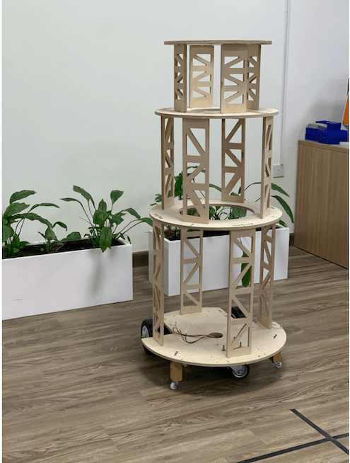
As shown in the image above the inner Structure of the robot.
| File | Link |
|---|---|
| The inner structure of the robot |
