TING's final project
Project Phases - Electronics Design
A. Design Requirement
The electronics must be able to handle the follow tasks:
- Intermittently turn on the QR30B, a DC brushless water pump to introduce fresh water into the anodic chamber. The input voltage required is 5V and typical current draw is about 500mA. A motor drive such as L298N is required. Since a voltage drop of about 2V is expected from the motor driver, a supply voltage of more than 7V is required.
- Read the volatge from the microbial fuel cell (MFC). The typical voltage ranges between 0.1 to 0.5V.
- Measure the temperature and humidity inside the electronic chamber to monitor for sign of water seepage into the electronic compartment. This is not critical to the functionality of the system and may be excluded from this first prototype and be included in the next improved version (spiral design).
- Compute and transmit the fuelcell voltage wirelessly via bluetooth to a handphone or laptop.
Design Considerations
- To drive the pump, besides VCC and GND, 3 digital pins are needed of which one must be a PWM pin. In terms of memory, the Sketch program is about 1.2Kb
- The voltage from the MCF must go into the ADC pin
- The data read by the microcontroller must be transmitted via the TX/RX pins
B. Atmega 328 Microcontroller
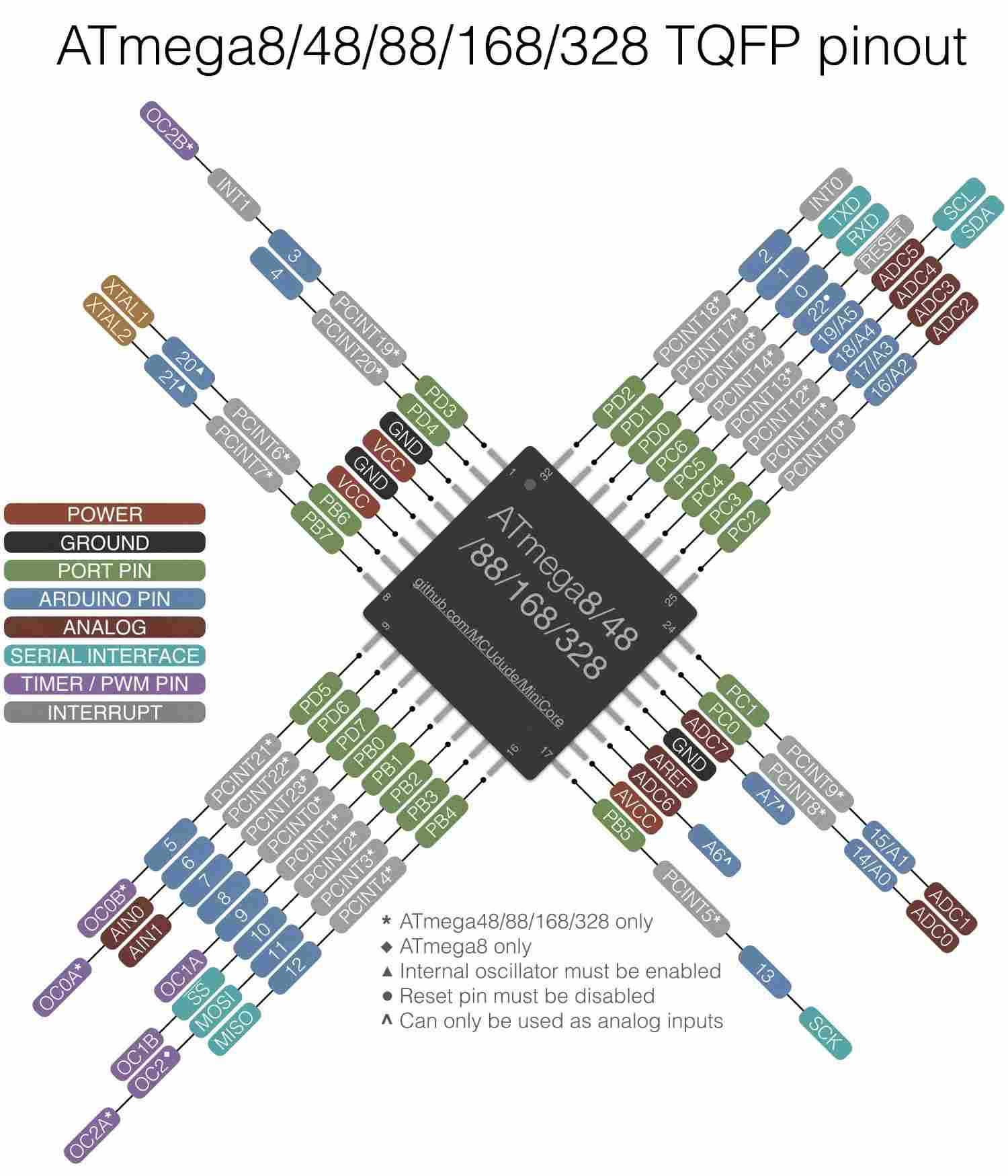
To use the Atmega 328 microcontroller properly, the first step is naturally to read the datasheet and study the pinout diagram.
The detailed datasheet is available from Microchip Website. Click HERE to download
- 32K Bytes of In-System self-programmable flash program memory
- 1 kBytes EEPROM
- 2 kBytes Internal SRAM
- Two 8-bit Timer/Counters with separate prescaler and compare mode
- One 16-bit Timer/Counter with separate prescaler, compare mode, and capture mode
- Real time counter with separate oscillator
- 32 x 8 general purpose working registers
- 6 PWM Channels
- 8-channel 10-bit ADC
- On-chip Analog Comparator
- Programmable configuration using Fuses
- Able to work between 2.7V and 5.5V
- Programmable Watchdog Timer with Separate On-chip Oscillator
- Speed Grade: 0 – 8 MHz @ 2.7 - 5.5V, 0 - 16 MHz @ 4.5 - 5.5V
C. Measuring Small Voltages
Since the voltage from the microbial fuelcell (MFC) is very small, special attention must be paid to the design. I referred to John Errington's webpage on precise voltage measurement with the Arduino board.
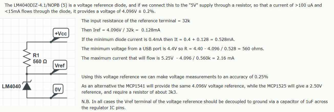
From the datasheet as well as from John Errington's page, the ATmega 328 is provided with a successive approximation type Analog to Digital converter (ADC) which has has an absolute accuracy of ± 2 LSB (Least Significant Bit). Hence the maximum error is 2 bits (4 decimal) in 10 bits (1024 decimal) and the worst case accuracy of the converter is 4/1024 or 0.25%. However the limit of the measurement accuracy largely depends largely on the voltage reference used. For high accuracy voltage measurement, external reference voltage is recommended as with internal reference voltage, accuracy is at best 5%. Below is an example from John Errington's webpage on how an external voltage can be setup.
C. Satshakit
Since I planned to use the ATmega 328, the best resource to get started it would be the Satshakit which is an Arduino compatible and most importantly fabbable board. Using this board as a starting point, I can get to design my board in EAGLES.
D. Designing my own board with EAGLES
Having identified the requirements for the circuit board, the next step is to select/determine the pins required. Besides PWM, ADC, TX and RX, I have also decided to include a ISP header on my board so that I can upload programs to my board easily using the USBTiny ISP that I have made a several weeks ago. I decided to use the 3.7V Li-ion battery to power my device. For the water pump which requires the L298 H-bridge a supply voltage of around 7V is required. Hence I have also include a buck boost converter.
Using Sashakit as the starting point and having fabricated 2 boards, the drawing of the schematic is quite smooth now.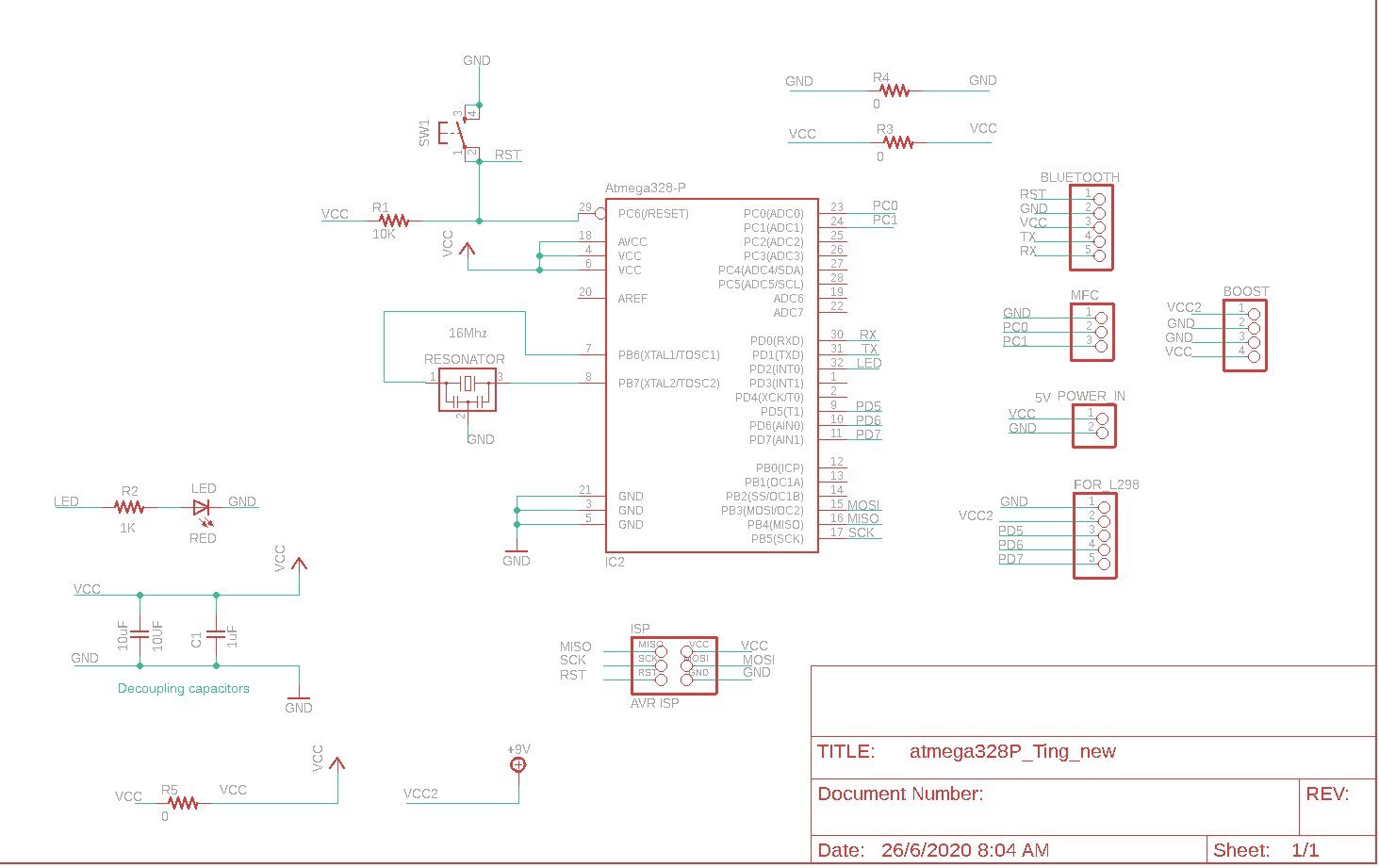
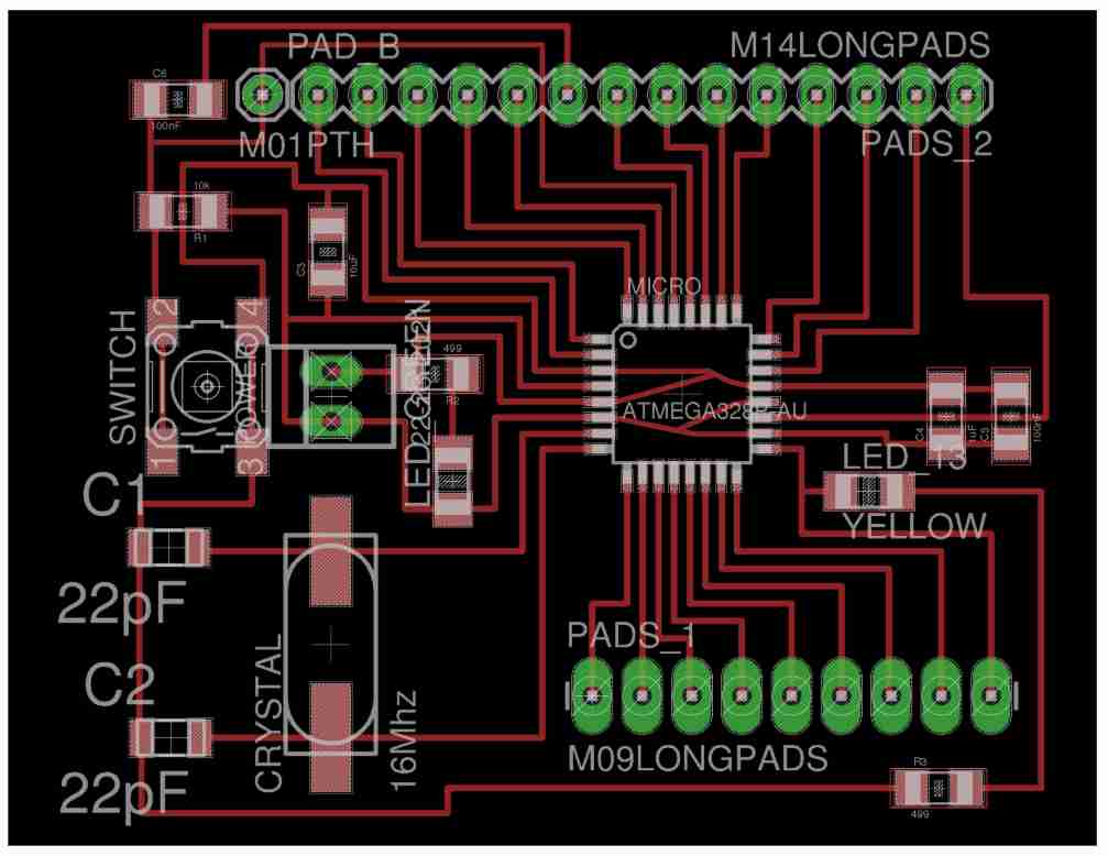
After clearing ERC check, the next step was to develop the board. Again using Sashakit's design as a guide, laying out and routing the board was much less daunting now. The design is as follows:
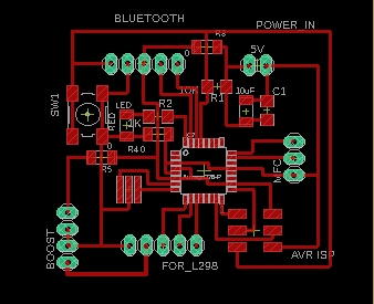
Once the routing of the board was completed, DRC was run. For the DRC, a spacing of 12 mils was used as the spacings between the pins for the ATmega 328P mcu are only 14 mils apart. After rectifying routing mistakes and approving airwires for the Zero-ohm resistors, the design was ready for fabrication.
E. Fabricating the board
To fabricate the board, StepCraft 420 milling machine was used. mods was used to generate the gcode (nc file). THe procedures for machine operation as well as gcode file generation were the same as when I fabricated my USBTiny ISP programmer and hence not documented here. The toolpath is as follows
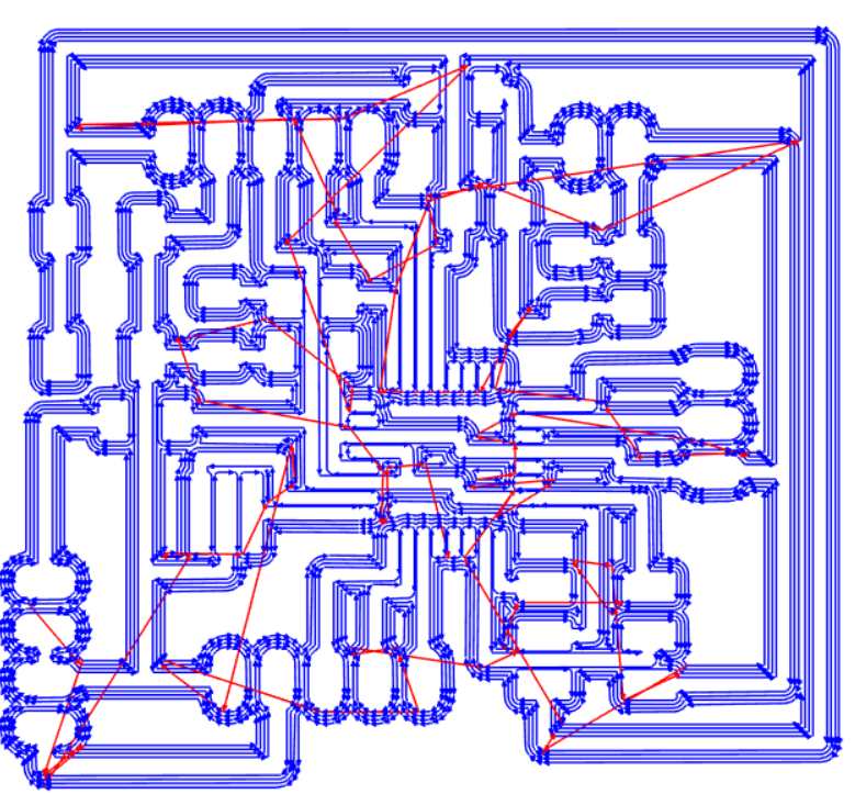
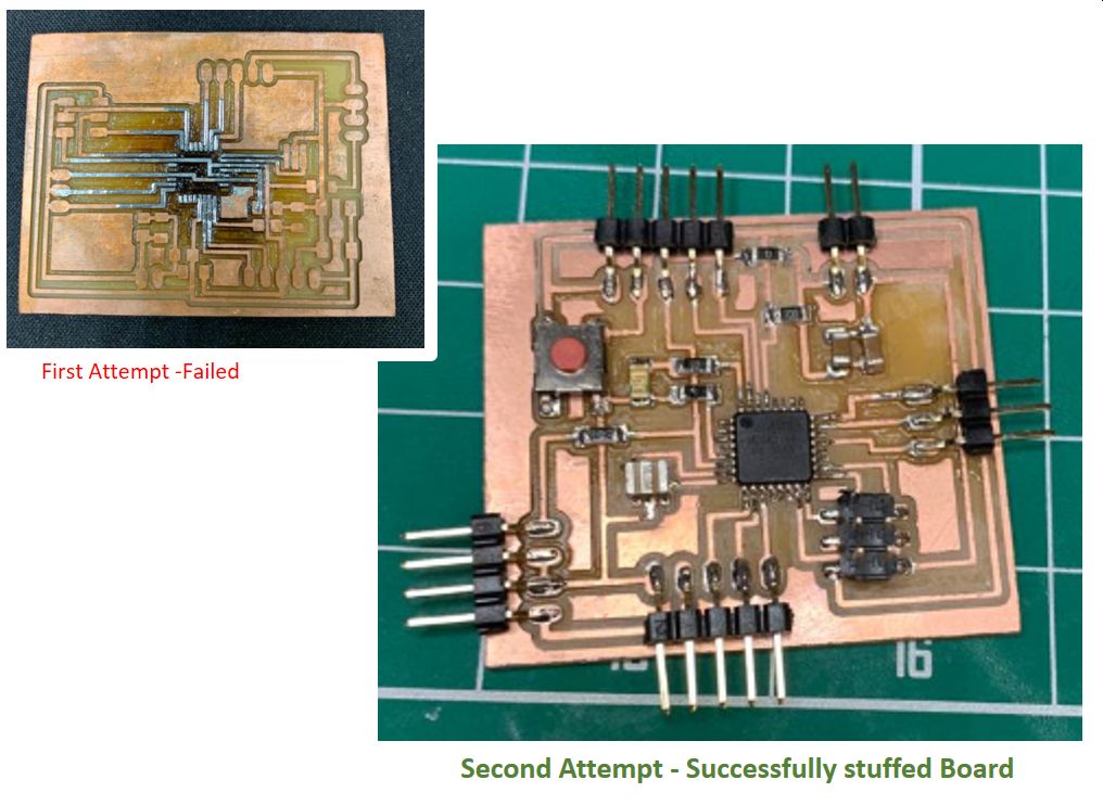
For milling 0.1mm 10 degree tool was used. After milling, the next mammoth task is the stuffing. Soldering Atmega 328P was a nightmare. I failed in my first attempt and when using the hot air gun for rework, I burnt the board and had to start all over again. The second attempt was successful and the image of the completed stuffed board is as follows:
To test that the board is working properly a small servo motor (SG90) was connected to the pins one at a time and the Sketch program was amended, compiled and run for each of the pin. The video below showed that the PWM pin was working properly.
The motor will turn 90 degree, pauses for 1 second, then turn another 180 degree, wait for 1 second then return to start position
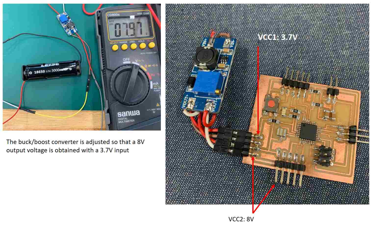
To power the 5V water pump, the L298 H-bridge is required and since a voltage drop of 2V across the H-bridge is expected (refer to Output Device Assignment for more details), a buck/boost converter was used, so that the voltage of 8V can be supplied to the H-bridge.