TING's final project
Assembly & Testing
PART 1 : Pump Mechanism
To get the pump to work properly, a supply of around 5V to 6V is required. The purpose of the pump is to bring fresh water into the anodic chamber before taking voltage reading, it need not be continuously on. Also, to allow flexibility in controlling the pump flowrate, the PWM pin will also be used. To drive the pump this way, the L-298 H-bridge is used.
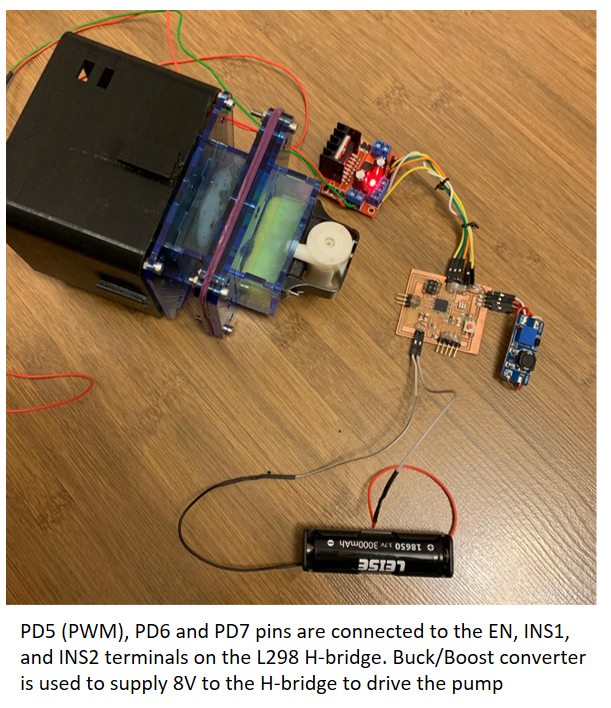
The pump will turn on for 2 seconds, off for 1 second and repeats
PART 2 : Voltage Reading and Bluetooth transmission to Android Phone
For voltage measurement, the ADC pin (PC1) is used. The bluetooth module HC-04 is connected to the Tx and RX pins on the Atmega chip (Pin 1 and Pin 0). For the Android handphone App, the MIT App Inventor is used.
MIT App Inventor is an intuitive, visual programming environment that allows everyone to build fully functional apps for smartphones and tablets. It is started by a small team of CSAIL staff and students, led by Professor Hal Abelson and today there are more than 8.2 million registered users from 195 countries. Till date more than 34 million Apps have been created with App Inventor.
I referred to the following websites to develop my App below:
Roboindia.com site 1Roboindia.com site 2
Electronoobs.com
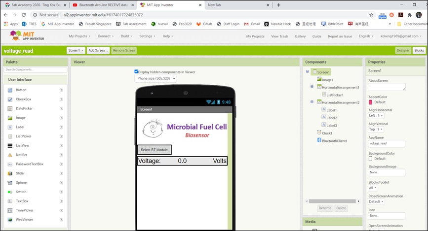 MIT App Inventor Web-Based interface
MIT App Inventor is web-based and is easy to use with many built-in programming blocks. These built-in blocks are available for a wide range of components.
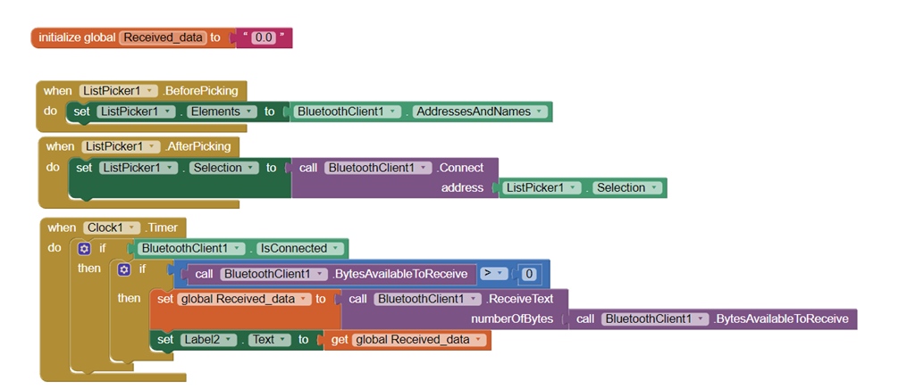 Using Blocks to create the program
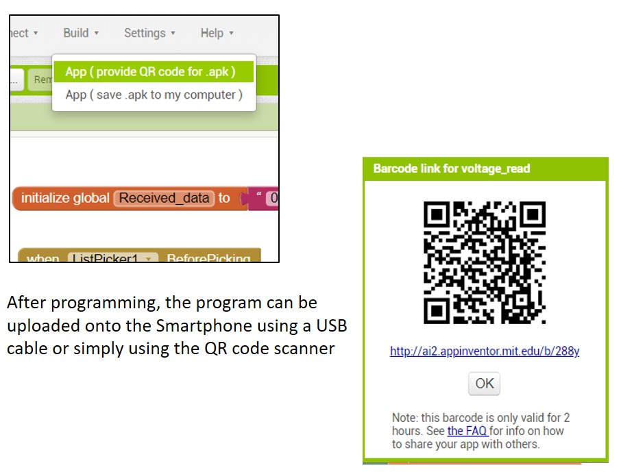 Uploading the App to the phone
Turning the potentiometer will change the voltage display on the smartphone app.
PART 3 : Tidying Up the PCB and Wiring
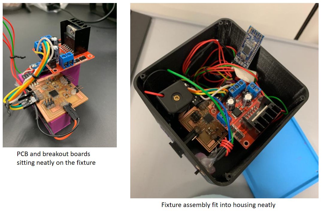
To arrange the PCB as well as the breakout boards, a fixture is designed using Fusion 360 and 3D printed.
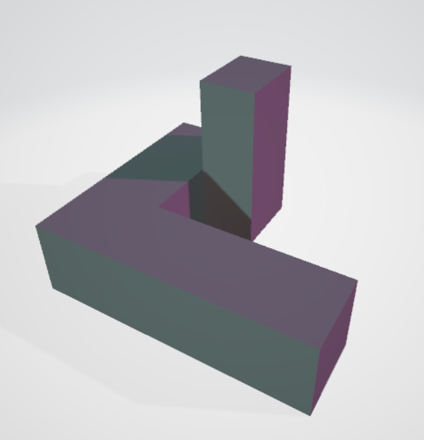
Custom-designed blocks for PCB and breakout boards
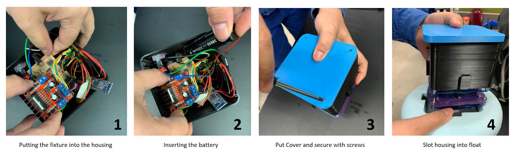
PART 4 : Assembly
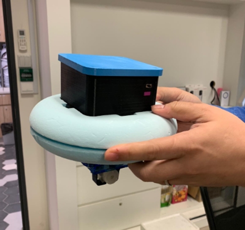
PART 5 : Final Test
The MFC is designed to sample every 10 minutes. Prior to reading and transmitting the voltage to the smartphone, the water pump will be on for 8 seconds to bring fresh solution to the anodic chamber. For the demostration video, the Sketch program is modified as follows:

Final Test
A 1-minute video and a project poster was created to summarise this final project.
Click Here to download Project Poster/Slide.
Click Here to download Project Video.