TING's final project
Project Phases 1 , and 3 - Mechanical Designs
(Phase 1A) MFC Chamber Design
Design Requirements
- The whole setup must be easily dissemble for cleaning purposes
- The whole setup must be able to be submerge in water for prolong duration.
- Wastewater (to be analyzed) must be able to enter and leave the anodic chamber periodically.
- Cathodic chamber must be water-tight to prevent loss of electrolyte to the wastewater
- PEM msut be secuely fastened such that liquids from the cathodic and anodic chambers do not come into contact with each other.
Based on the above design requirement, the design of the first prototype MFC is as follows. I used Fusion 360 to design the parts. Parametric design is used for these drawings as the thickness of the acrylic sheets that I will be using is not decided yet. The files are as below:
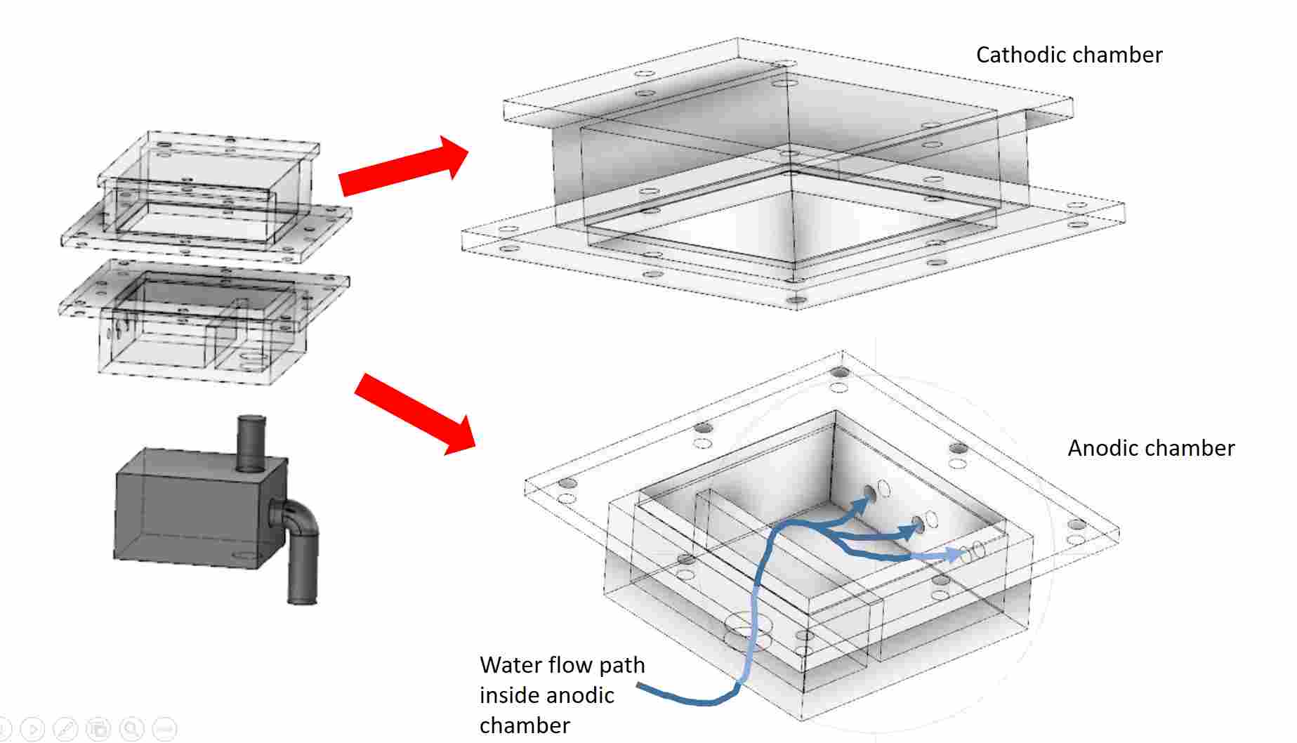
Overall Design of the MFC
The anodic chamber of the MFC does not need to be water-tighted and hence press-fit design using laser cutting would be an easy and fast method of fabrication. An opening at the base allows the submersible pump outlet to be inserted inside the anodic chamber. Clear acrylic will be used since the part will be submerged in water for prolong period. A baffle within will help to distribute the water evenly inside the chamber.
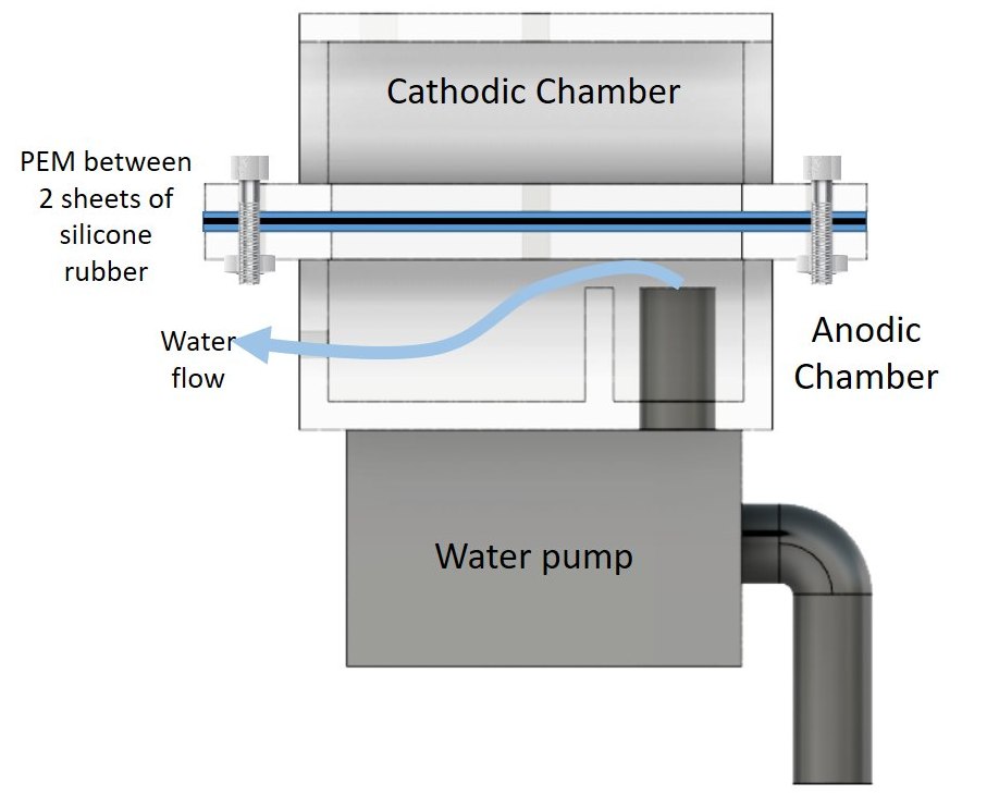
Side View showing water flow path
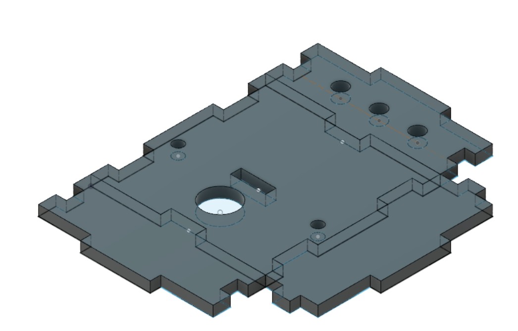
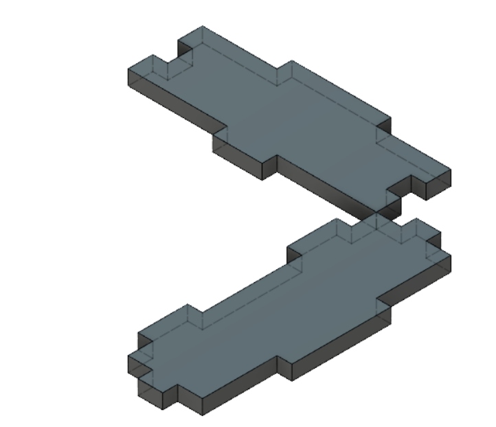
Anodic Chamber: Base and Sides
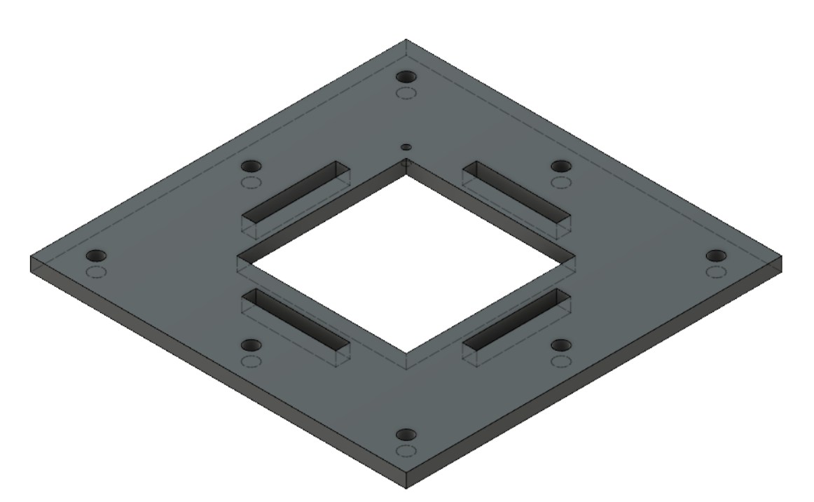
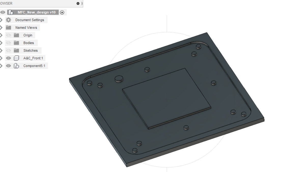
Anodic Chamber Top Piece (also the cathodic base)
For the Cathodic chamber, although it must be water-tight to prevent the loss of electrolyte, for aesthetic reason, the same fabrication technique and material as the anodic chamber will be used. After assembly, silicone glue will be applied on all the edges in the interior to prevent the electrolyte from leaking out.
Cathodic Chamber Sides: Same dimensions as Anodic chamber but with no opening
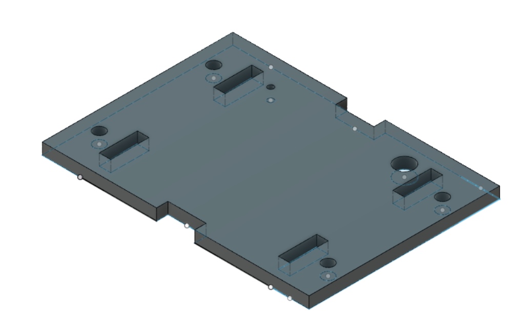
Cathodic Chamber: Top
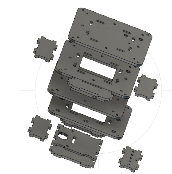
Exploded View of the MFC
(Phase 1B) MFC Chamber Fabrication
After laser cutting the parts on 3 mm clear acrylic, the pieces are press fit togther to form the cathodic and anodic chambers. To ensure that the cathodic chamber is water-tight, epicote 1003 clear epoxy resin is used. I have used this in the Mold & Casting assignment and found this resin to have very low vicosity and is able to fill tiny gaps. The steps are summarised below.
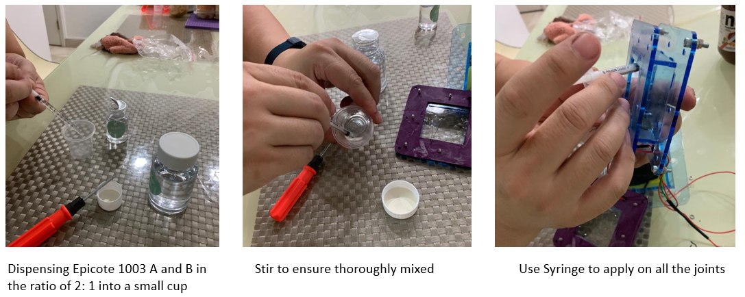
Using clear epoxy resin to make cathodic chamber water tight
(Phase 1C) Making Carbon Cloth Electrodes
For both electrodes, conductive carbon cloth is used. Squares measureing 40mm x 40mm are cut and stitch together to form the electrodes. The steps are summarised below

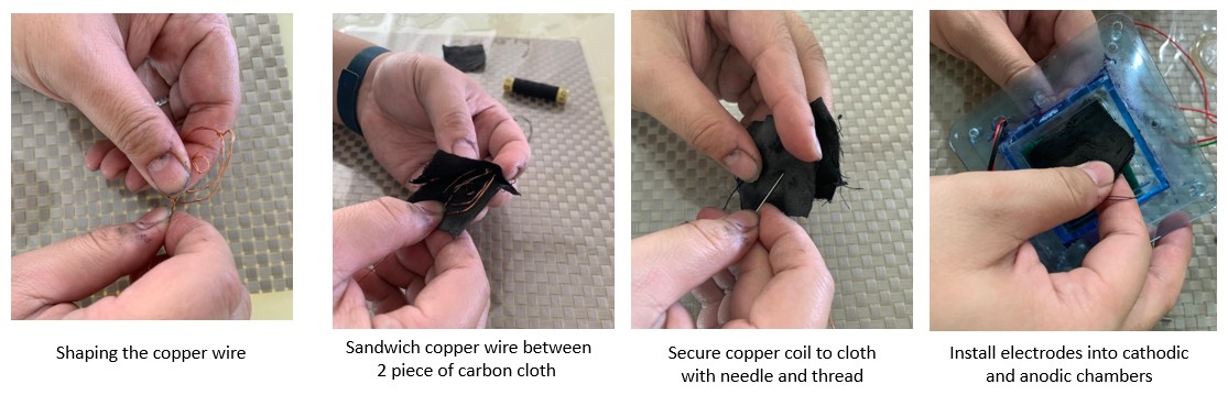
Making Electrodes with Carbon Cloth
(Phase 1D) Making Silicone Gaskets
To hold the proton exchang membrane (PEM) firmly in place and prevent electrolyte solution from leaking out from the cathodic chamber, 2 customed made silicone gaskets were produced. 3D printing was used to create the mold and EasyMold Silicone Putty was used.
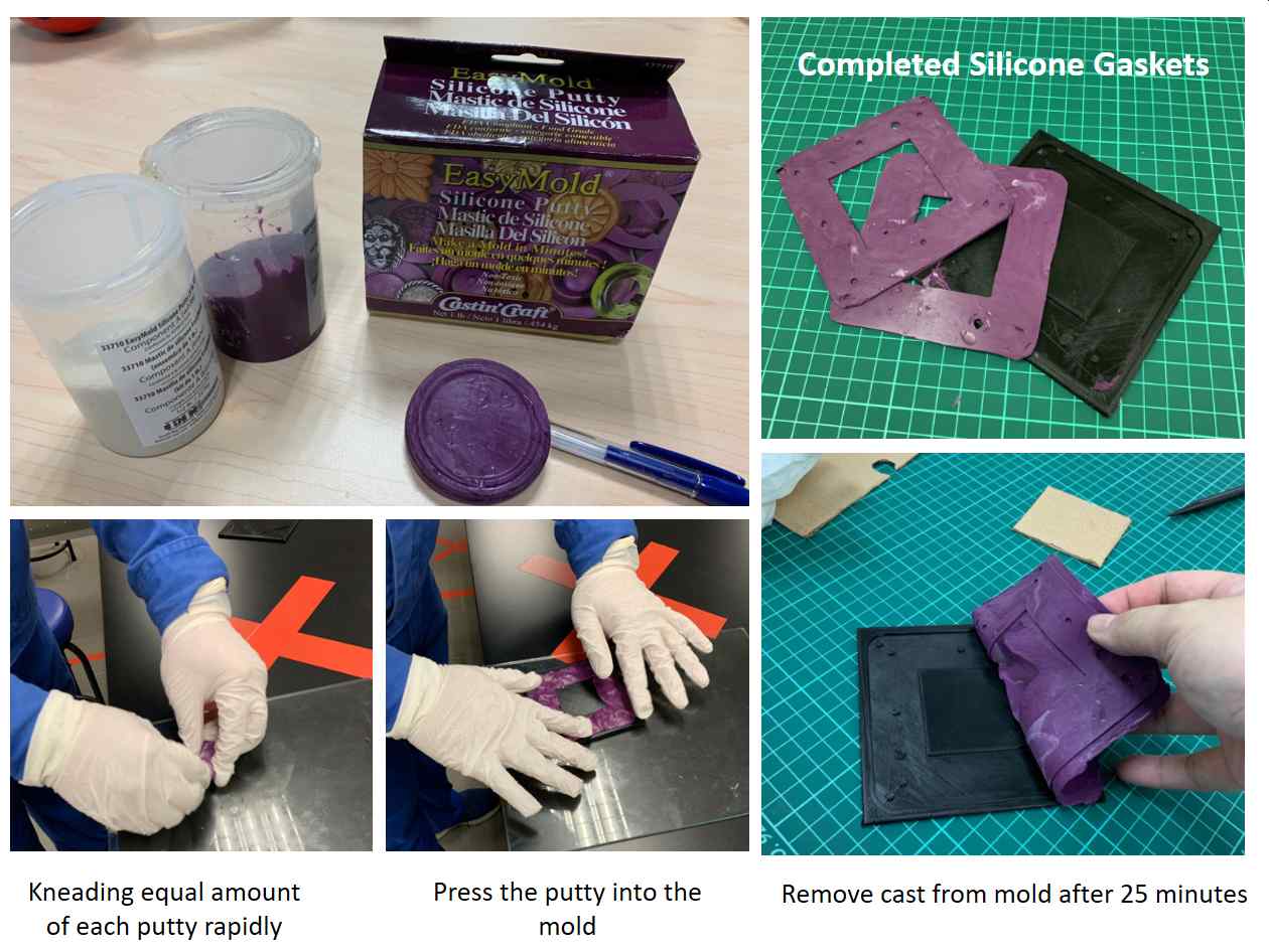
Custom-made silicone gaskets for better seal.
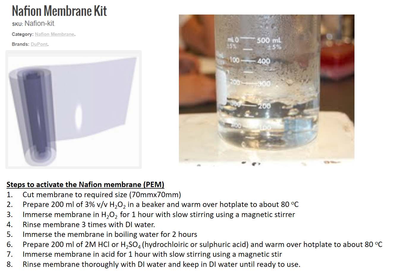
(Phase 1E) Activating the Proton Exchange Membrane (PEM)
For this fuelcell biosensor, the Nafion proton exchange membrane from Dupont is used. Prior to use, the membrane must be chemically treated (or activated). The procedure for the activated is as follows:
(Phase 1F) Assembling Cathodic Chamber
After making and leak-proofing the acrylic MFC chambers, sewing the carbon cloth electrodes, casting the silicone gaskets and activating the proton exchange membrane (PEM), the final step is to assmeble them together. The steps are summarised below:
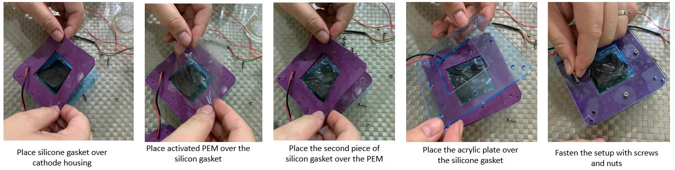
Steps to assemble the Cathodic Chamber
After assembling the cathodic chamber, the next step is to fill the cathodic chamber with electrolyte solution. For this test, saturated sodium chloride (NaCl, common salt) solution is used. The solution is introducted into the cathodic chamber from the top using a syringe and a rubber stopper is used to seal the opening after filling the electrolyte solution. The steps are summarised below.
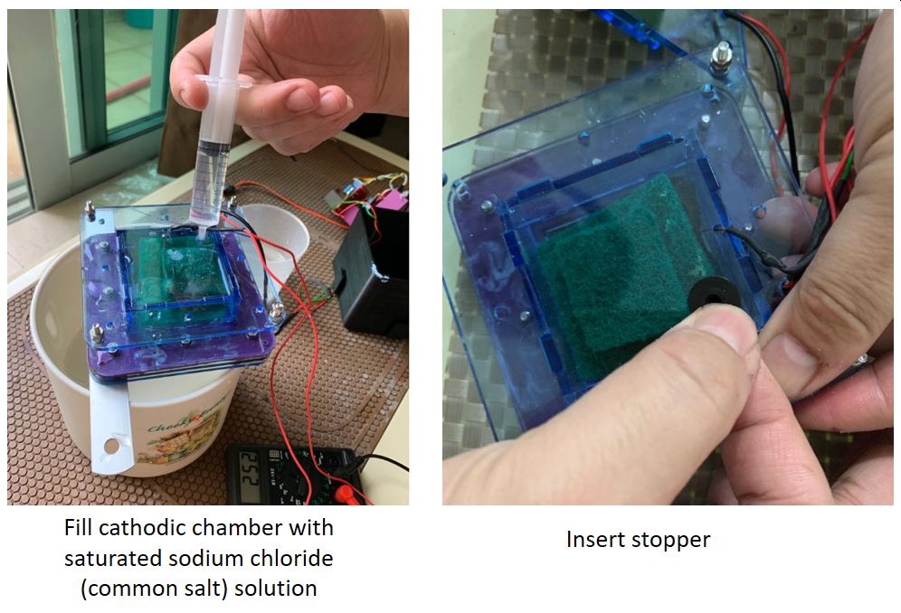
Filling Cathodic Chamber with Electrolyte solution
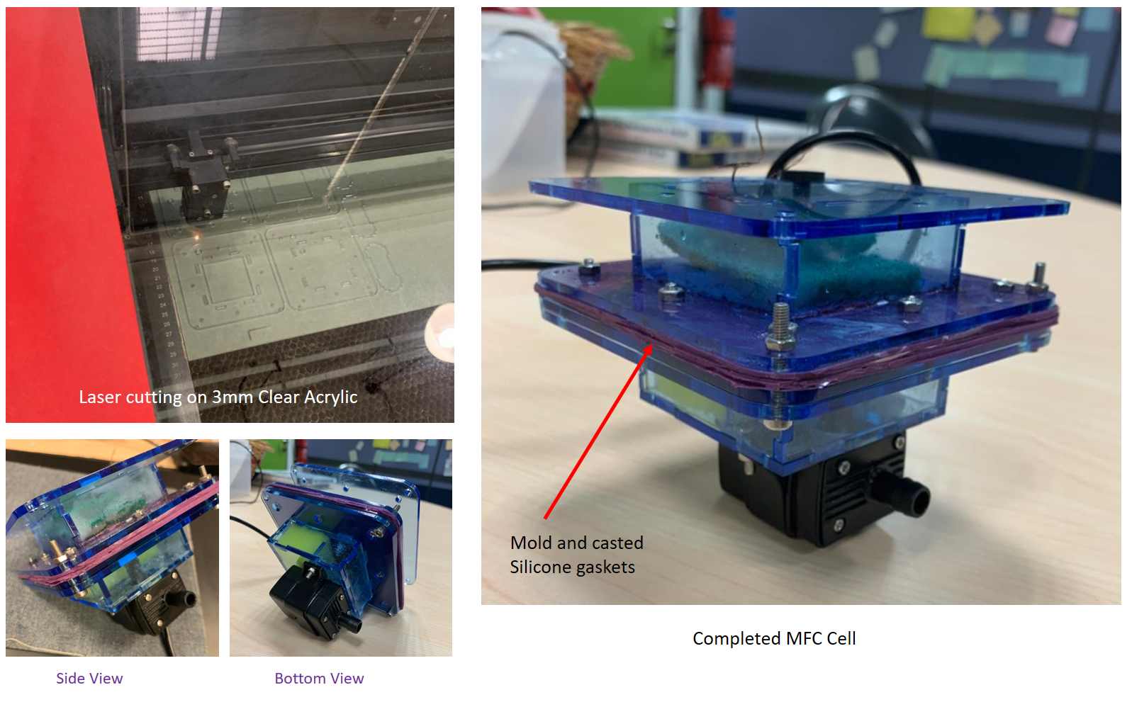
Completed MFC with water pump attached.
Although the QR30B water pump is working fine with the L298 H-bridge and buck converter, the power consumption is actually quite high at 2.3W. To prolong the operating duration between charge, a low power micro-submersible pump from Toolstar is used instead. The new design is shown below. This pump has a power consumption of only 0.4W.
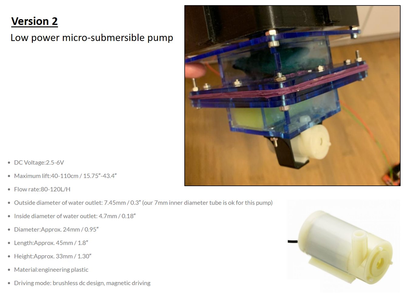
Completed MFC with new water pump attached.
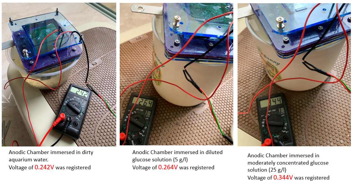
(Phase 1GF) Functional Check
To check that the fuelcell is functioninf properly, the anodic chamber is filled with different solutions. Readings of between 0.242V to 0.344V were obtained for different solutions indicating that the MFC is working properly.
(Phase 2) Housing for Electronics
Design Requirements
- The housing must be water-tight yet must be able to open for battery change
- The PCBs must be able to be secured firmly to the housing (by screws)
- Bluetooth signal must be able be transmitted out from the housing
- Housing must be big enough to house the PCB boards and a battery
- Housing must enable the float to be attached to it firmly
Based on the above design requirement, the preliminary design of the housing is as follows:
I plan to use 3-D printing to fabricate the housing as it allows the board/s to be mounted by screws.
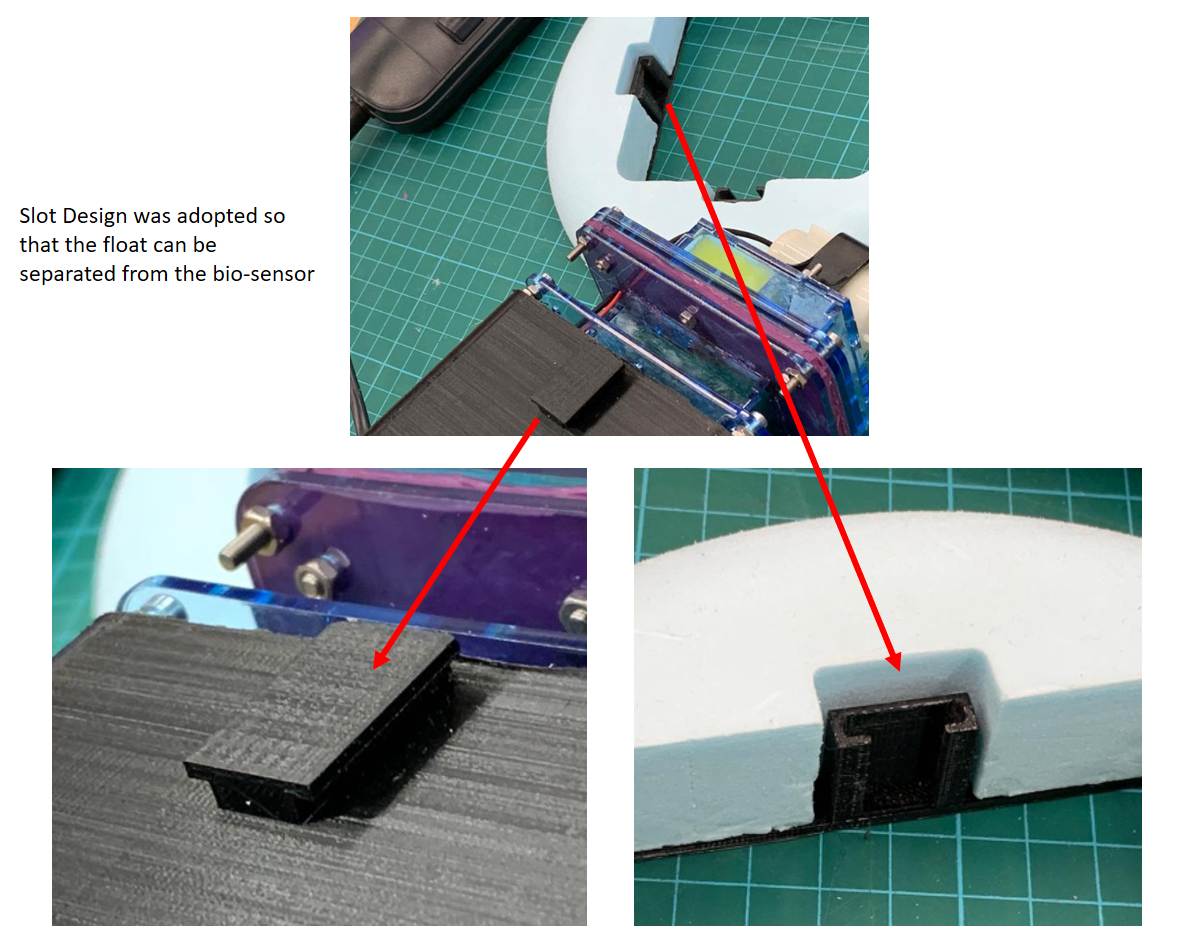
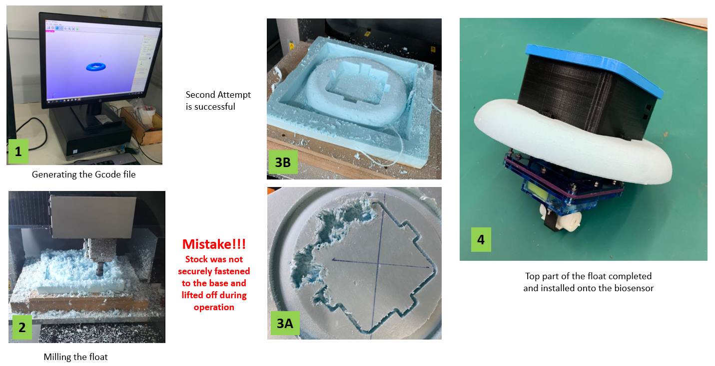
In order to allow damaged parts to be changed easily, the above design was modified so that the float mechanism can be separated from the setup. A slot-in design was adopted as illustrated in the imgaes below.
For the Molding and Casting assignment, the Roland Modela ProII MDX-540 desktop CNC machine was not available and we used the StepCraft 420 milling machine instead, hence for the final project, I decided to use the Roland MDX-540 to make the float.
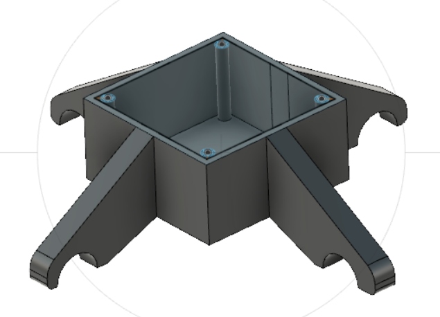
Housing
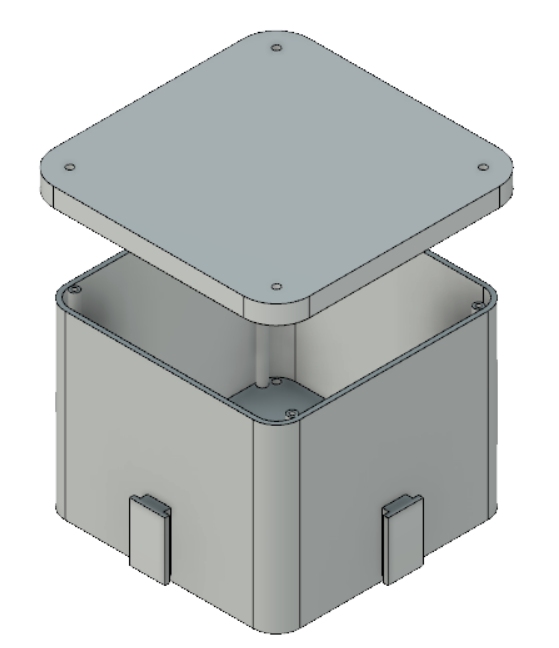
For the housing, a simple rectangular box design was adopted as it is strong, easy for water-proofing and fast to fabricate.
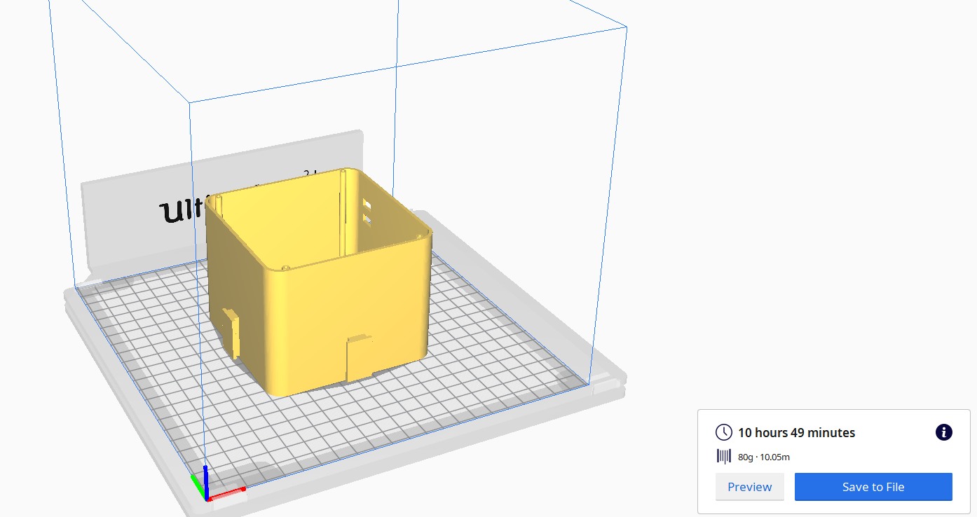
After designing the housing, the file is saved in STL format and opened in the 3D prinitng software Cura to generate the gcode code file for 3D printing. Below is an image from the Cura software. Even with an infill of 5%, the printing of the housing alone will still take more than 10 hours to complete! I realised that by setting the wall thickness as 2mm, it is too narrow for any infill and as such the walls have to be printed as a solid sheet, using numerous passes resulting in the long print time.
Completed MFC
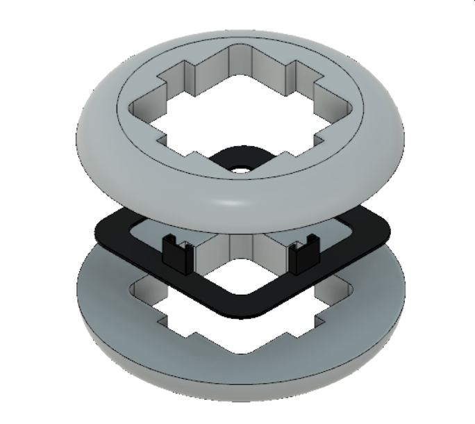
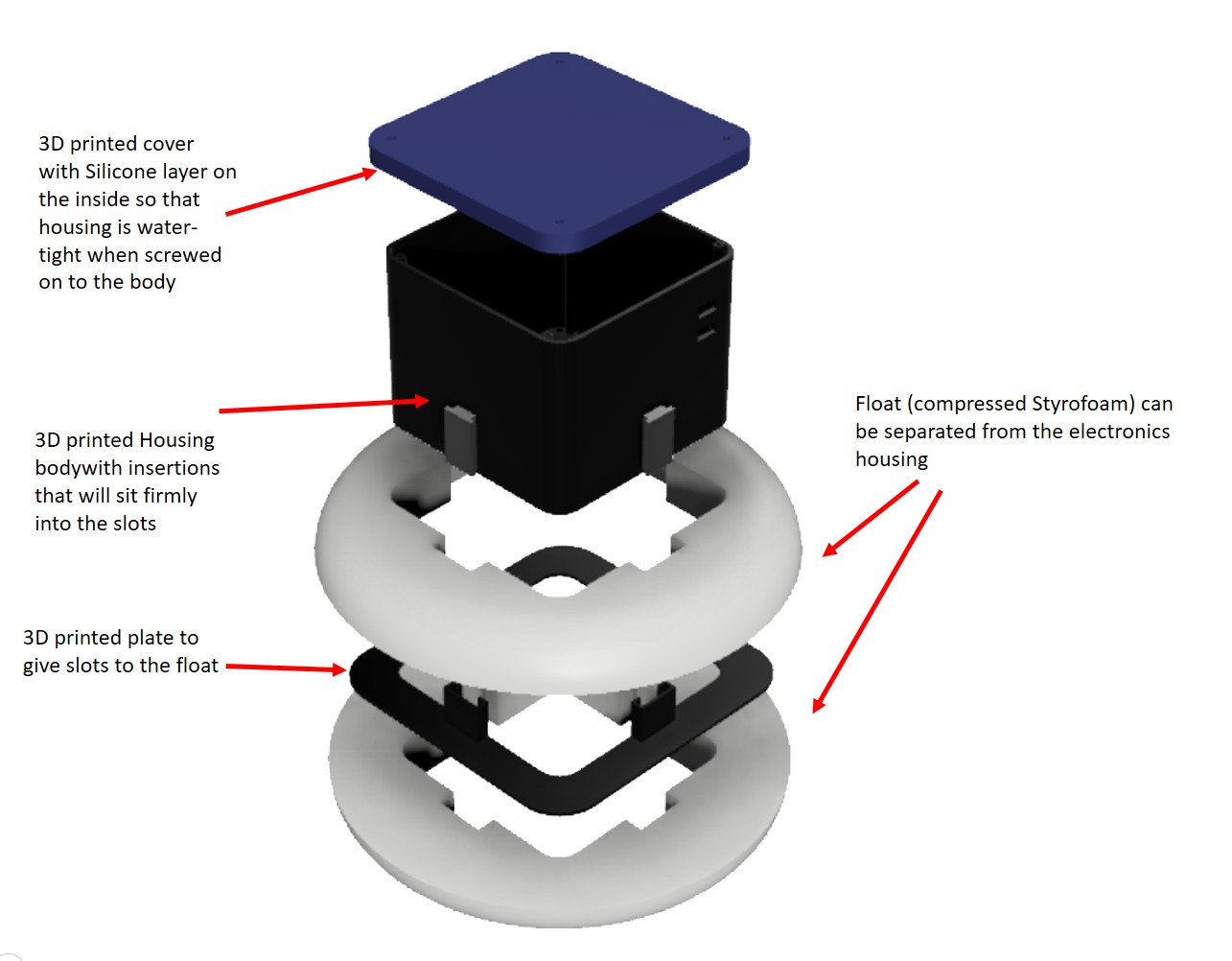
Below is the exploded view of the housing and the float as well as the video of the completed design floating on water.
Floating on water