iot light switch / dimmer knob
electronics design
main assignment - board design
This week I am designing a small board around the ESP-WROOM-32 module.
The ESP-WROOM-32 is a very feature-rich module, containing two CPU cores,
a WiFi and BLE radio, capacitive sensing (and many other) peripherals, and
supports running in a low power operation mode.
I am designing a control panel for IoT lights around it to control the (Philips Hue brand) smart lights in our home with.
On the board there will be a rotary encoder with a builtin switch (Bourns PEC11R), six 3535 RGB LEDs (WS2812B-mini), and the necessary Serial connection header and boot/program switches.
I have used the LEDs and encoder with an FPGA before, and done some basic capacitive touch sensing on the knob via the mounting pins and the conductive shaft of the encoder. I’m hoping to use the advanced capsense peripheral of the ESP32 to wake the board up when it is touched, so that it can be used immediately.
For the board design, I am using KiCAD. Here is the schematic:

The reset and programming circuit is taken directly from Neil’s hello-board design. The WS2812Bs are connected to a random I/O pin, since the ESP32 has extensive I/O MUX capabilities. The encoder signals are passively filtered using the recommended filtering network from the datasheet, and routed to inputs that are accessible to the low-power processor (RTC pins). This way I will have full flexibility with regard to powersaving features when I get to the firmware development phase.
After some trial and error, I managed to lay out the whole board on a single layer without any jumpers (or jumper resistors). This took quite a while and multiple redesigns, but I’m pretty happy with the result. Here are renders of the full board:
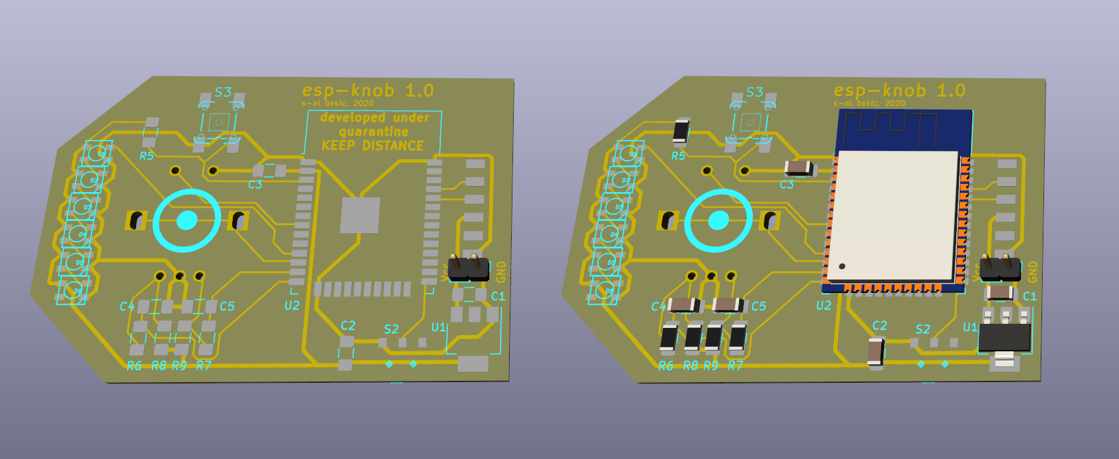
I also used the excellent InteractiveHTMLBOM Kicad plugin to generate this interactive BOM/board view.
And the individual layers (traces, through-holes, outline; SVG with mm units):


I exported these using the File > Export > SVG feature in pcbnew:
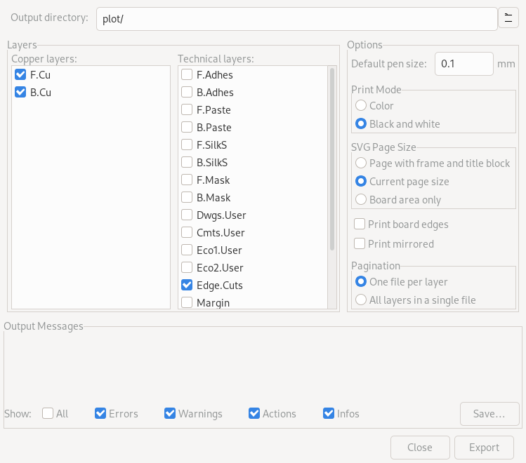
The through-hole and outline SVGs need some post-processing in Inkscape to be
usable with mods; In the drill file (which is simply the B.Cu layer showing
the pads and holes), all the drilled holes have to be colored black (slots have
to be converted to filled shapes using Path > Stroke to Path). Then the pads
around the holes can be deleted.
For the outline image, the outline first has to be converted to a complete
shape. First everything should be ungrouped. Then, with all parts of the path
selected, they can be merged using Path > Combine. However this doesn’t
create a filled shape yet: using the Edit paths by node tool, all vertices
have to be selected and then joined using the Join selected Nodes button.
At this point a solid shape should be visible after adjusting the Fill color
and alpha. Now a rectangle can be created using the rectangle tool. It should
span over the whole document and be filled in black. It can then be sent to the
background. Finally, with both the rectangle and the board shape selected,
applying Path > Difference should leave you with a black canvas and the board
outline as a solid white shape, ready for mods.
The SVGs can then be milled out using the default mods programs: The outline and drill paths both use the ‘outline’ preset, and in fact could be done in a single pass, the two files are only separate to ensure proper ordering: while the through-holes are milled, the board should be fixed securely still.
The original fabmodules.org implementation for Roland MDX machines supported the MDX-15, MDX-20, MDX-40 and SRM-20 via a dropdown list. When mods was created, the general structure was reused, but apparently only the MDX-25 variant was implemented.
In the end, there are only very small differences between the different models: the MDX-15 and MDX-20 have a lower resolution (0.025mm) whereas the MDX-40 and SRM-20 make steps of 0.01mm. Since the RML file format describes positions in terms of machine steps, the NC code has to be generated taking the correct scale factor into account.
Apart from the step size, the only other value that differs in is the home position. Once I found this information in the original source, I could update the new implementationto also support all of the four models. This patch has been applied to the mods community edition, which you can try out online: fabfoundation.github.io/mods.
Unfortunately, due to the ongoing health crisis I do not currently have access
to the lab, and so fabbing the board has to wait currently.
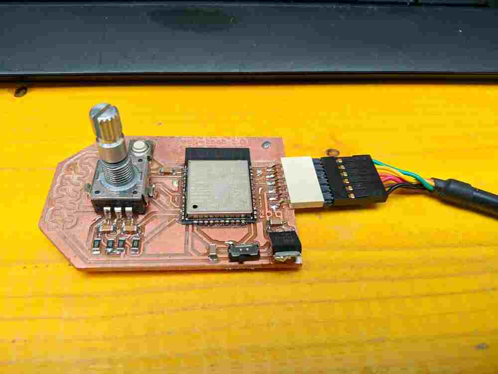
When I returned to the lab, I could make the board with the toolpaths generated using fabmodules (see above) and stuff it. I decided to use solderpaste and a hot-air rework station, since the ESP32 has very small castellated pads (and even a completely covered ground pad on the underside).
kludges
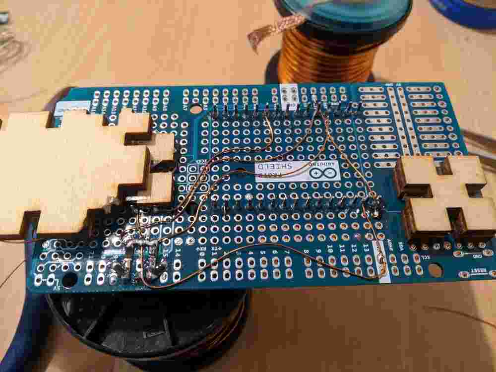
It turned out that we didn’t stock the voltage regulator in the size that I had designed for, so I went up one size and used some copper enamel wire to connect the output paddle to where it was supposed to go.
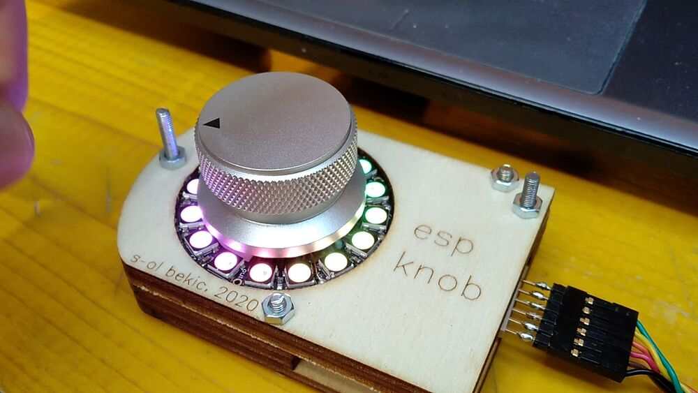
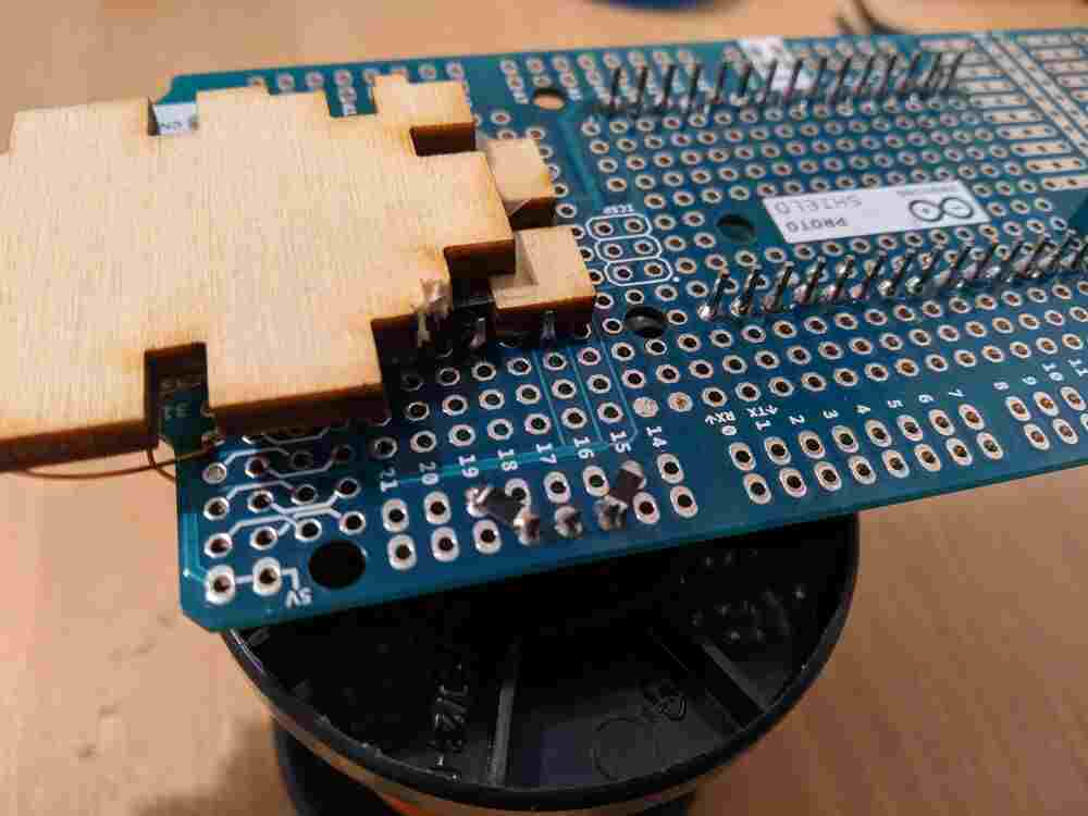
I also realized that I did not have the 3535 WS2812B-minis that I thought I did anymore. Instead, I found an Adafruit Neopixel ring which complimented the size of the aluminum knob I was going to use well. Since they use the same protocol, I simply left the LED pads unpopulated, and hooked up 3.3V, ground and the data-in pin with more enamel wire:
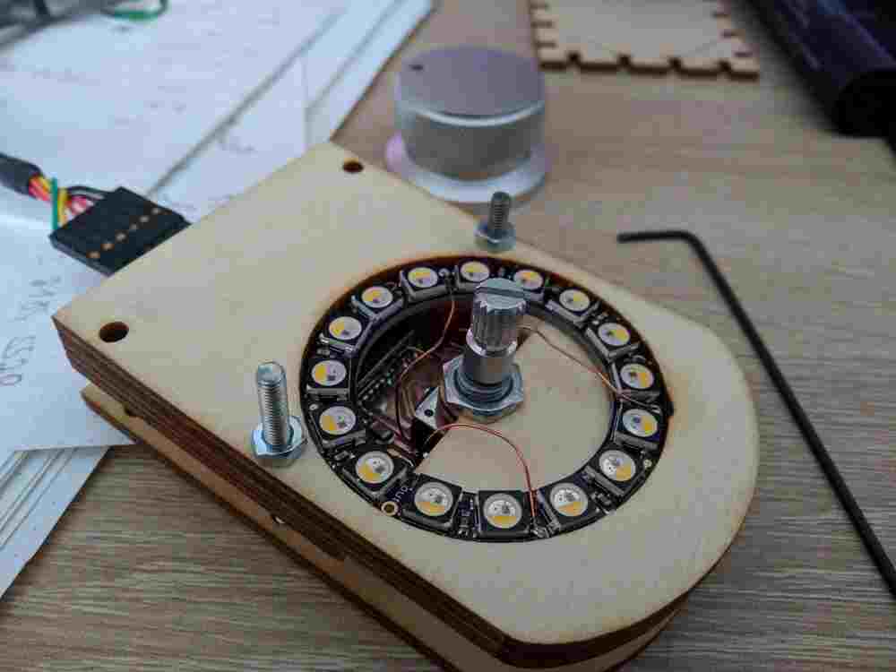
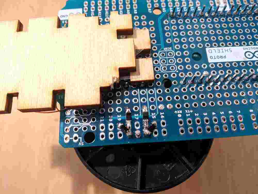
I also laser-cut a case that clamps down on the PCB from both sides and holds the LED ring and encoder in place:

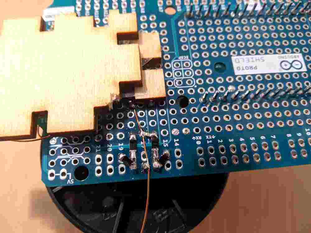
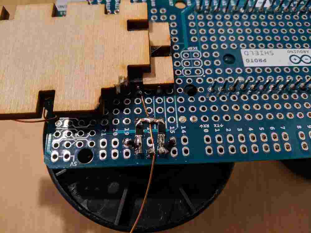
During bringup I noticed another mistake: the GPIO12 pin I used as the A-input for the encoder’s quadrature signals is actually a bootloader pin, and if it is pulled high when the chip is powered, the board cannot be flashed. I fixed this by cutting the old trace between the filtered encoder output and the GPIO pin (IO12) and instead connecting it to IO25 with more copper enamel wire.
bringup
Since the main circuitry of this board is based on Neil’s ESP32 hello board, the programming process is the same: the slide switch selects whether the board will wait for new code or boot the application on the next reboot. After changing its position, the board has to be reset either by power-cycling or pressing the reset button.
Like for the ‘later’ embedded programming
projects (that I actually finished before this work, during
lockdown), I used the esp-idf toolchain. With the board connected with a
TTL-232R-5V FTDI USB-Serial cable and in flash-mode, make flash is enough
to build and upload the project. See the linked log for more information on
setting up esp-idf).
This little clip shows everything the hello board does: It lights up the LED ring in all hues, with one LED being off. By turning the knob, the LED that is turned off can be rotated around the ring. While the knob is touched, the saturation of all LEDs is increased. When the knob is pressed down, a rainbow cycling animation is played back.
files
- KiCAD source files
- BoM and assembly instructions
- SVG files for board milling (see above)
- SVG Files for case (see above)
- C project (zip)
embedded programming
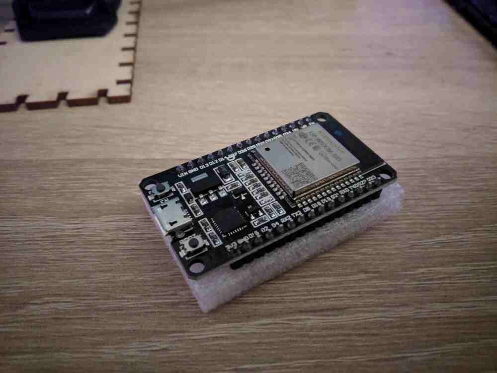
Due to the current health crisis I wasn’t able to manufacture the board I designed two weeks ago (or have it manufactured), but after some weeks of delay we were able to organise an ESP32 dev kit. The specific board I have is a “JZK”-branded board based around the same ESP-WROOM-32D module that I based my design on, and appears to be a clone of the ‘DoIt ESP32’ dev board. It really isn’t much more than a breakout board for the module, with some added status LEDs, a builtin USB-Serial bridge and 3V3 regulator. There are also two buttons onboard to manually reset the module and put it into ‘BOOT’ mode (both of these should also be possible via UART, since the board also contains the ‘auto reset’ circuit).
While it is possible to program a high-level langauge interpreter like
CircuitPython, Lua or JS onto the ESP32, I wanted to practice my C. I started
by downloading the Espressif development framework esp-idf via the
git AUR package. The setup was a little complicated, but after some
trial and error I finally got the older version 3.3.1 to work: As per the
AUR package, I installed the SDK to /opt/esp-idf, but unlike the package
says, the python dependencies are actually necessary for python2. In the SDK
configuration, python2 has to be set as the interpreter for each project as
well, and I also had to remove the ,<2.4.0 from the pyparsing line in
/opt/esp-idf/requirements.txt (I guess it was there for a reason, but I
haven’t had any issues). Following this, I ran /opt/esp-idf/install.sh
and then . /opt/esp-idf/export.sh from a bash shell.
I started by compiling the blink example (copied from
/opt/esp-idf/examples/get-started/blink/). To write some files in
/opt/esp-idf the first build requires elevated permissions, so I ran make
and make menuconfig once each from a root shell. After that, successive builds
can be done from a user shell with no problems. I set the GPIO to blink to GPIO
2 (the one that has an onboard LED on my dev board) using make menuconfig,
then built the example (make) and flashed it to the board (make flash):
Next I tried the hello_world example, which demonstrates use of the Serial
port. I copied, compiled and flashed it as above, and finally started the
Serial monitor using make monitor:
MONITOR
--- idf_monitor on /dev/ttyUSB0 115200 ---
--- Quit: Ctrl+] | Menu: Ctrl+T | Help: Ctrl+T followed by Ctrl+H ---
ets Jun  8 2016 00:22:57

rst:0x1 (POWERON_RESET),boot:0x13 (SPI_FAST_FLASH_BOOT)
configsip: 0, SPIWP:0xee
clk_drv:0x00,q_drv:0x00,d_drv:0x00,cs0_drv:0x00,hd_drv:0x00,wp_drv:0x00
mode:DIO, clock div:2
load:0x3fff0018,len:4
load:0x3fff001c,len:6712
load:0x40078000,len:12072
load:0x40080400,len:6708
entry 0x40080778
I (71) boot: Chip Revision: 1
I (72) boot_comm: chip revision: 1, min. bootloader chip revision: 0
I (39) boot: ESP-IDF v3.3.1-dirty 2nd stage bootloader
I (39) boot: compile time 18:06:53
I (39) boot: Enabling RNG early entropy source...
I (44) boot: SPI Speed      : 40MHz
I (48) boot: SPI Mode       : DIO
I (52) boot: SPI Flash Size : 4MB
I (57) boot: Partition Table:
I (60) boot: ## Label            Usage          Type ST Offset   Length
I (67) boot:  0 nvs              WiFi data        01 02 00009000 00006000
I (75) boot:  1 phy_init         RF data          01 01 0000f000 00001000
I (82) boot:  2 factory          factory app      00 00 00010000 00100000
I (90) boot: End of partition table
I (94) boot_comm: chip revision: 1, min. application chip revision: 0
I (101) esp_image: segment 0: paddr=0x00010020 vaddr=0x3f400020 size=0x07e5c ( 32348) map
I (122) esp_image: segment 1: paddr=0x00017e84 vaddr=0x3ffb0000 size=0x01e9c (  7836) load
I (125) esp_image: segment 2: paddr=0x00019d28 vaddr=0x40080000 size=0x00400 (  1024) load
0x40080000: _WindowOverflow4 at /opt/esp-idf/components/freertos/xtensa_vectors.S:1779

I (131) esp_image: segment 3: paddr=0x0001a130 vaddr=0x40080400 size=0x05ee0 ( 24288) load
I (149) esp_image: segment 4: paddr=0x00020018 vaddr=0x400d0018 size=0x12cb0 ( 76976) map
0x400d0018: _flash_cache_start at ??:?

I (177) esp_image: segment 5: paddr=0x00032cd0 vaddr=0x400862e0 size=0x02124 (  8484) load
0x400862e0: vTaskSwitchContext at /opt/esp-idf/components/freertos/tasks.c:4560

I (185) boot: Loaded app from partition at offset 0x10000
I (186) boot: Disabling RNG early entropy source...
I (188) cpu_start: Pro cpu up.
I (192) cpu_start: Application information:
I (197) cpu_start: Project name:     hello-world
I (202) cpu_start: App version:      1
I (206) cpu_start: Compile time:     Mar 29 2020 18:06:55
I (212) cpu_start: ELF file SHA256:  dc0ce2df83339a2b...
I (218) cpu_start: ESP-IDF:          v3.3.1-dirty
I (224) cpu_start: Starting app cpu, entry point is 0x40080ee0
0x40080ee0: call_start_cpu1 at /opt/esp-idf/components/esp32/cpu_start.c:269

I (0) cpu_start: App cpu up.
I (234) heap_init: Initializing. RAM available for dynamic allocation:
I (241) heap_init: At 3FFAE6E0 len 00001920 (6 KiB): DRAM
I (247) heap_init: At 3FFB2EC8 len 0002D138 (180 KiB): DRAM
I (253) heap_init: At 3FFE0440 len 00003AE0 (14 KiB): D/IRAM
I (260) heap_init: At 3FFE4350 len 0001BCB0 (111 KiB): D/IRAM
I (266) heap_init: At 40088404 len 00017BFC (94 KiB): IRAM
I (272) cpu_start: Pro cpu start user code
I (291) cpu_start: Starting scheduler on PRO CPU.
I (0) cpu_start: Starting scheduler on APP CPU.
Hello world!
This is ESP32 chip with 2 CPU cores, WiFi/BT/BLE, silicon revision 1, 4MB external flash
Restarting in 10 seconds...
Restarting in 9 seconds...
Restarting in 8 seconds...
Restarting in 7 seconds...
Restarting in 6 seconds...
Restarting in 5 seconds...
Restarting in 4 seconds...
Restarting in 3 seconds...
Restarting in 2 seconds...
Restarting in 1 seconds...
While the esp-idf toolchain in general is a bit overbearing, it does work quite well. Programming with it really cannot be considered very ‘bare-metal’, as there are tons of things going on behind-the-scenes, in fact there is all of freeRTOS running. I have never worked with a realtime OS before, and playing with the examples a bit it does seem quite useful - it provides very useful primitives for task scheduling, message queues etc.
I found an interesting article that describes the process for compiling a bare-metal project for the ESP32 that was very nice to read, but at this stage I didn’t want to make my life any harder. If the process seemed easier than the esp-idf toolchain I would have considered it, but it actually also depends on some of the tools provided as part of esp-idf.
Both the toolchain and the ESP32 itself are extremely overpowered for my application (and I suspect the large majority of all applications they are used in…) which is at odds with my aspirations to use technology well and effectively. However the sake of learning, and since this is a one-off project that will not see any kind of larger-scale production, I think this is okay.
low-power modes
While designing the board in week 06, I researched the ESP32-WROOM module extensively to find information such as the pin assignments with respect to the various subsystems and peripherals in the ESP32. With this in mind, I placed all user-input pins (the encoder pins and switches) on pins that have both a GPIOxx and an RTC_GPIOx assignment (see ESP32-WROOM datasheet sect. 2), so that the chip can be woken up from deep sleep or hibernation when the knob is moved, pressed or touched. In Hibernation mode, the ESP32 can draw as little as 5uA (see ESP32 datasheet, sect. 3.7), which would enable the whole project to be battery powered.
input devices
After bringing up the ESP32 dev board itself up successfully, last week, I continued by soldering the encoder and its filtering network to the protoboard. I followed the schematic from the electronics design assignment closely, so that my code for this prototype would transfer directly to a board fabbed later.
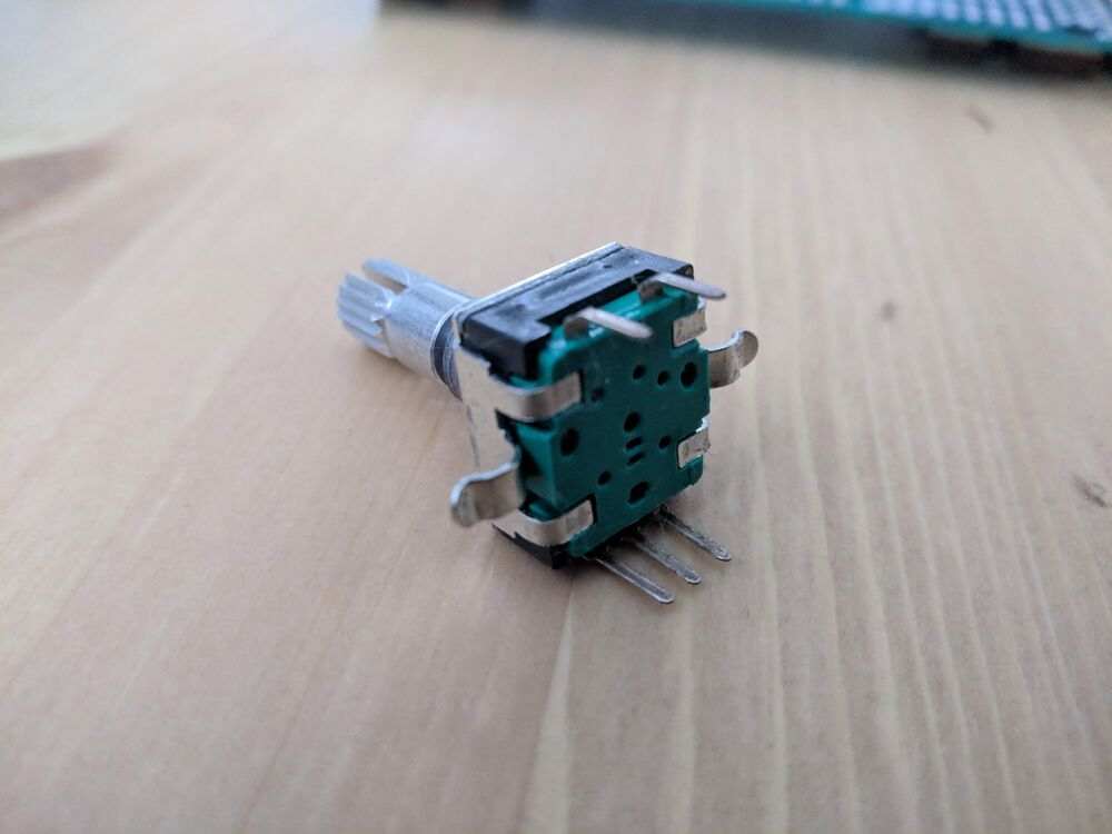
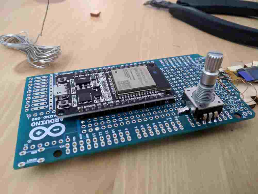
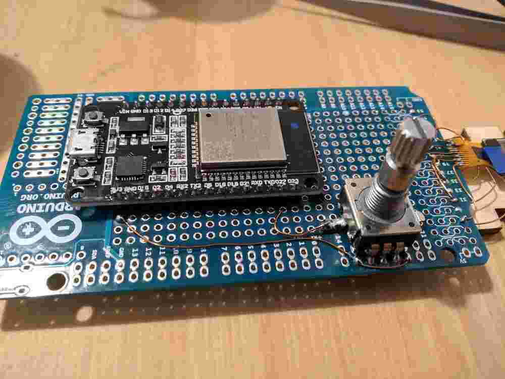
To fit the encoder on the protoboard, I had to bend the two big mechanical mounting pins to the side with pliers. I soldered one of them to a random pad for extra stability, but the five regular pins probably would have been strong enough on their own.
For implementing the capacitive sensing, I looked at the
peripherals/touch_pad_read and peripherals/touch_pad_interrupt examples, as
well as the peripherals/gpio example to get a basic understanding of the
Touch and GPIO APIs, which are also documented here and
here on the Espressif API docs.
Using the touch_pad_read example, I figured out that I had mis-wired the
mounting pin of the encoder, which I am using for capacitive sensing. I had
wired it to GPIO 22 rather than 27… the silkscreen on this knock-off dev
board is really low resolution. Once it was wired correctly, I saw that the
filtered touch value was resting at around 900 at default settings, and
dropped to a value between 100 and 300 (depending on contact pressure,
humidity…). A threshold of 400 worked very well to detect touching of the
encoder:
I then converted my code to an interrupt-based execution model
and factored the Serial output and LED blinking into its own FreeRTOS Task,
connected by a Queue (like in the gpio example). I moved on to add support
for switch pressing and encoder rotation, but noticed quickly that there was
something very wrong with the encoder pins A and B. I got the switch working
soon, but still don’t know what is up with them - it seems as if both sides
are shorted together and to 3V3? I am still not sure how that is physically
possible, given that they are not also shorted to GND, which is the only shared
node in the filtering network, but I will have to investigate more. I am a bit
skeptical of the resistors I used, because they are unmarked, while the other
resistors (from the same brand) I got in the same order all have their values
marked properly.