embedded programming
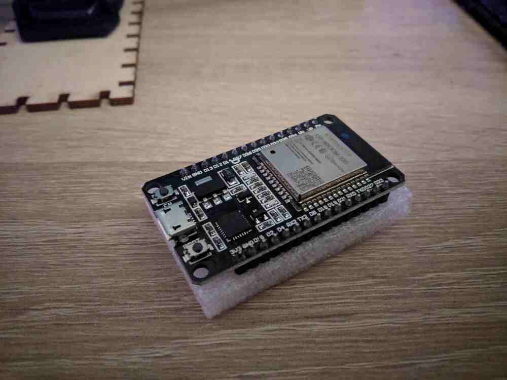
Due to the current health crisis I wasn’t able to manufacture the board I designed two weeks ago (or have it manufactured), but after some weeks of delay we were able to organise an ESP32 dev kit. The specific board I have is a “JZK”-branded board based around the same ESP-WROOM-32D module that I based my design on, and appears to be a clone of the ‘DoIt ESP32’ dev board. It really isn’t much more than a breakout board for the module, with some added status LEDs, a builtin USB-Serial bridge and 3V3 regulator. There are also two buttons onboard to manually reset the module and put it into ‘BOOT’ mode (both of these should also be possible via UART, since the board also contains the ‘auto reset’ circuit).
While it is possible to program a high-level langauge interpreter like
CircuitPython, Lua or JS onto the ESP32, I wanted to practice my C. I started
by downloading the Espressif development framework esp-idf via the
git AUR package. The setup was a little complicated, but after some
trial and error I finally got the older version 3.3.1 to work: As per the
AUR package, I installed the SDK to /opt/esp-idf, but unlike the package
says, the python dependencies are actually necessary for python2. In the SDK
configuration, python2 has to be set as the interpreter for each project as
well, and I also had to remove the ,<2.4.0 from the pyparsing line in
/opt/esp-idf/requirements.txt (I guess it was there for a reason, but I
haven’t had any issues). Following this, I ran /opt/esp-idf/install.sh
and then . /opt/esp-idf/export.sh from a bash shell.
I started by compiling the blink example (copied from
/opt/esp-idf/examples/get-started/blink/). To write some files in
/opt/esp-idf the first build requires elevated permissions, so I ran make
and make menuconfig once each from a root shell. After that, successive builds
can be done from a user shell with no problems. I set the GPIO to blink to GPIO
2 (the one that has an onboard LED on my dev board) using make menuconfig,
then built the example (make) and flashed it to the board (make flash):
Next I tried the hello_world example, which demonstrates use of the Serial
port. I copied, compiled and flashed it as above, and finally started the
Serial monitor using make monitor:
MONITOR
--- idf_monitor on /dev/ttyUSB0 115200 ---
--- Quit: Ctrl+] | Menu: Ctrl+T | Help: Ctrl+T followed by Ctrl+H ---
ets Jun  8 2016 00:22:57

rst:0x1 (POWERON_RESET),boot:0x13 (SPI_FAST_FLASH_BOOT)
configsip: 0, SPIWP:0xee
clk_drv:0x00,q_drv:0x00,d_drv:0x00,cs0_drv:0x00,hd_drv:0x00,wp_drv:0x00
mode:DIO, clock div:2
load:0x3fff0018,len:4
load:0x3fff001c,len:6712
load:0x40078000,len:12072
load:0x40080400,len:6708
entry 0x40080778
I (71) boot: Chip Revision: 1
I (72) boot_comm: chip revision: 1, min. bootloader chip revision: 0
I (39) boot: ESP-IDF v3.3.1-dirty 2nd stage bootloader
I (39) boot: compile time 18:06:53
I (39) boot: Enabling RNG early entropy source...
I (44) boot: SPI Speed      : 40MHz
I (48) boot: SPI Mode       : DIO
I (52) boot: SPI Flash Size : 4MB
I (57) boot: Partition Table:
I (60) boot: ## Label            Usage          Type ST Offset   Length
I (67) boot:  0 nvs              WiFi data        01 02 00009000 00006000
I (75) boot:  1 phy_init         RF data          01 01 0000f000 00001000
I (82) boot:  2 factory          factory app      00 00 00010000 00100000
I (90) boot: End of partition table
I (94) boot_comm: chip revision: 1, min. application chip revision: 0
I (101) esp_image: segment 0: paddr=0x00010020 vaddr=0x3f400020 size=0x07e5c ( 32348) map
I (122) esp_image: segment 1: paddr=0x00017e84 vaddr=0x3ffb0000 size=0x01e9c (  7836) load
I (125) esp_image: segment 2: paddr=0x00019d28 vaddr=0x40080000 size=0x00400 (  1024) load
0x40080000: _WindowOverflow4 at /opt/esp-idf/components/freertos/xtensa_vectors.S:1779

I (131) esp_image: segment 3: paddr=0x0001a130 vaddr=0x40080400 size=0x05ee0 ( 24288) load
I (149) esp_image: segment 4: paddr=0x00020018 vaddr=0x400d0018 size=0x12cb0 ( 76976) map
0x400d0018: _flash_cache_start at ??:?

I (177) esp_image: segment 5: paddr=0x00032cd0 vaddr=0x400862e0 size=0x02124 (  8484) load
0x400862e0: vTaskSwitchContext at /opt/esp-idf/components/freertos/tasks.c:4560

I (185) boot: Loaded app from partition at offset 0x10000
I (186) boot: Disabling RNG early entropy source...
I (188) cpu_start: Pro cpu up.
I (192) cpu_start: Application information:
I (197) cpu_start: Project name:     hello-world
I (202) cpu_start: App version:      1
I (206) cpu_start: Compile time:     Mar 29 2020 18:06:55
I (212) cpu_start: ELF file SHA256:  dc0ce2df83339a2b...
I (218) cpu_start: ESP-IDF:          v3.3.1-dirty
I (224) cpu_start: Starting app cpu, entry point is 0x40080ee0
0x40080ee0: call_start_cpu1 at /opt/esp-idf/components/esp32/cpu_start.c:269

I (0) cpu_start: App cpu up.
I (234) heap_init: Initializing. RAM available for dynamic allocation:
I (241) heap_init: At 3FFAE6E0 len 00001920 (6 KiB): DRAM
I (247) heap_init: At 3FFB2EC8 len 0002D138 (180 KiB): DRAM
I (253) heap_init: At 3FFE0440 len 00003AE0 (14 KiB): D/IRAM
I (260) heap_init: At 3FFE4350 len 0001BCB0 (111 KiB): D/IRAM
I (266) heap_init: At 40088404 len 00017BFC (94 KiB): IRAM
I (272) cpu_start: Pro cpu start user code
I (291) cpu_start: Starting scheduler on PRO CPU.
I (0) cpu_start: Starting scheduler on APP CPU.
Hello world!
This is ESP32 chip with 2 CPU cores, WiFi/BT/BLE, silicon revision 1, 4MB external flash
Restarting in 10 seconds...
Restarting in 9 seconds...
Restarting in 8 seconds...
Restarting in 7 seconds...
Restarting in 6 seconds...
Restarting in 5 seconds...
Restarting in 4 seconds...
Restarting in 3 seconds...
Restarting in 2 seconds...
Restarting in 1 seconds...
While the esp-idf toolchain in general is a bit overbearing, it does work quite well. Programming with it really cannot be considered very ‘bare-metal’, as there are tons of things going on behind-the-scenes, in fact there is all of freeRTOS running. I have never worked with a realtime OS before, and playing with the examples a bit it does seem quite useful - it provides very useful primitives for task scheduling, message queues etc.
I found an interesting article that describes the process for compiling a bare-metal project for the ESP32 that was very nice to read, but at this stage I didn’t want to make my life any harder. If the process seemed easier than the esp-idf toolchain I would have considered it, but it actually also depends on some of the tools provided as part of esp-idf.
Both the toolchain and the ESP32 itself are extremely overpowered for my application (and I suspect the large majority of all applications they are used in…) which is at odds with my aspirations to use technology well and effectively. However the sake of learning, and since this is a one-off project that will not see any kind of larger-scale production, I think this is okay.
low-power modes
While designing the board in week 06, I researched the ESP32-WROOM module extensively to find information such as the pin assignments with respect to the various subsystems and peripherals in the ESP32. With this in mind, I placed all user-input pins (the encoder pins and switches) on pins that have both a GPIOxx and an RTC_GPIOx assignment (see ESP32-WROOM datasheet sect. 2), so that the chip can be woken up from deep sleep or hibernation when the knob is moved, pressed or touched. In Hibernation mode, the ESP32 can draw as little as 5uA (see ESP32 datasheet, sect. 3.7), which would enable the whole project to be battery powered.