electronics production
main assignment - prototyping methods
For the main assignment, I wanted to try a couple of different prototyping methods. Apart from breadboarding and processes involving the creation of full PCBs (by milling or etching), the following methods seem to be reasonably well known:
- ‘freeform electronics’
- ‘dead-bug’
- ‘manhattan style’
- ‘ugly style’
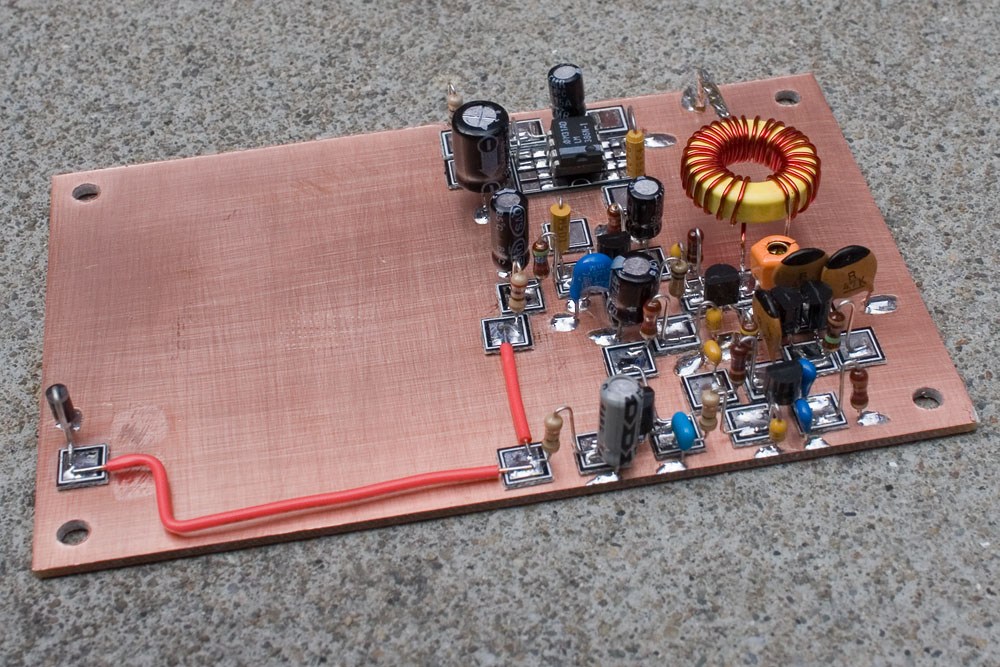
 The ‘ugly style’ uses a single copper ground plane that most components are
soldered to to provide structural support for components. All other connections
are made either directly between component leads, or, if necessary, using wire.
The approach is not very suitable to SMD prototyping, because it relies on pins
making contact to the ground plane as the (sole) structural framework. Since SMD
components have no or very short leads, this is essentially impossible.
The ‘ugly style’ uses a single copper ground plane that most components are
soldered to to provide structural support for components. All other connections
are made either directly between component leads, or, if necessary, using wire.
The approach is not very suitable to SMD prototyping, because it relies on pins
making contact to the ground plane as the (sole) structural framework. Since SMD
components have no or very short leads, this is essentially impossible.
 Manhattan style on the other hand uses small rectangles of cut copper boards to
create ‘islands’ that serve as common pads to connect different components. It
is essentially impossible to hand-make such copper pads reliable to sizes that
are compatible with SMD pitch sizes reliably. It would also be extremely hard
to connect components due to the absence of long leads that can be bent and
routed.
Manhattan style on the other hand uses small rectangles of cut copper boards to
create ‘islands’ that serve as common pads to connect different components. It
is essentially impossible to hand-make such copper pads reliable to sizes that
are compatible with SMD pitch sizes reliably. It would also be extremely hard
to connect components due to the absence of long leads that can be bent and
routed.
 Freeform electronics rely on no mechanical support other than the solder joints
and wiring. This requires wire that is mechanically strong enough to support
components, and requires a temporary solution for keeping components in place
during production. Unlike most other styles, freeform electronics can take full
advantage all three spatial dimensions.
Freeform electronics are not easier or faster to produce than other prototyping
styles by far, and are generally produced for artistic value of the production
style. It is common to encapsulate freeform electronics by casting them in
epoxy after manufacturing, which helps isolate the circuit and also provides
structural support, while also being an aesthetic design element.
Freeform electronics rely on no mechanical support other than the solder joints
and wiring. This requires wire that is mechanically strong enough to support
components, and requires a temporary solution for keeping components in place
during production. Unlike most other styles, freeform electronics can take full
advantage all three spatial dimensions.
Freeform electronics are not easier or faster to produce than other prototyping
styles by far, and are generally produced for artistic value of the production
style. It is common to encapsulate freeform electronics by casting them in
epoxy after manufacturing, which helps isolate the circuit and also provides
structural support, while also being an aesthetic design element.
Dead-bug prototyping uses a non-conductive substrate, to which components are
affixed using adhesive. Components are usually placed upside down (therefore
the name). Wiring between components is often done using enameled wire, which
is very flexible and easy to de-insulate using heat from the soldering iron.
So given the remarks above, I wanted to try constructing a programmer each using the later two methods. For both methods, the choice of wire to use is quite important, so I had to coordinate with my lab to get the right resources. In the end i chose the following two wires:
- 0.35mm diameter (27AWG) copper enamelled wire (from RS online)
- 1.12mm diameter (17AWG) copper enamelled wire (from RS online)
Here are the two wires next to two SMD ICs: on the left is a FT230XS-R FTDI IC, on the right an ATTiny45:

Due to the fine pitch on the FT230XS, I finally decided to only try to solder a SPI programmer using the ATTiny45 and the deadbug soldering technique. I chose the FabTinyStar board design by Brian because it uses the comparatively coarse-pitch ATTiny45 and a rather small amount of passives.
Before getting started, I took the original schematic and flipped it horizontally in Gimp, since using the deadbug technique all ICs are seen from the opposite side. Flipping the pinouts mentally may not seem too difficult, but during focused soldering session there are many chances to get it wrong and one is essentially bound to make a mistake without proper preparation. After flipping the whole schematic, I also flipped some of the pin names back around (every column individually!) to make them readable again.

I used a piece of cardboard that I taped down on the work surface as a substrate, and double-sided sticky tape to keep the components tacked down. Neither of these choices was ideal, but as I am currently locked out of the lab due to health concerns I had to make do with what I had. The double-sided tape in particular was problematic, since the adhesive has a tendency to disintegrate when heated. The excess heat from soldering often caused components to loosen from the substrate and caused much stress during soldering.
Here is the result after soldering:

Following the instructions of the FabTinyStar, I flashed the firmware onto the
board. Since I didn’t have another programmer handy, I used an Arduino uno with
the “ArduinoISP” sketch from the Arduino examples. This effectively turns it
into an avrisp programmer. To make this work with the FabTinyStar Makefile,
some small adjustments were necessary: In all $(AVRDUDE) commands, the
-c $(PROGRAMMER) -P usb has to change to -c avrisp -P /dev/ttyACM0 -b 19200
(the Serial port name and baud rate may vary, depending on your system and the
settings you made when flashing ArduinoISP).
After flashing the firmware, I plugged it into USB and saw it being recognized by the system:

So I went ahead and wrote the fuses. At this point I was starting to have intermittent problems with some solder joints, whenever I fixed one another would come loose rather soon. Despite this, I got the fuses set up, but I wasn’t able to get the programmer to reflash the Arduino Uno’s bootloader :(