
SBP autolevelling PCB process
This post is mostly a description of how and why I developed the sbp-pcb-autolevel code the way I did. For the code, installation and usage instructions please see the repository.
Creating large PCBs using a milling process can be quite a challenge, as I found out while working on my final project. I milled 152x152mm double-sided PCB stock, and the subtle warping and height differences in the PCB stock made it very hard to consistently engrave the surface without either cutting too deep and removing the adjacent track, or cutting too shallowly and shorting out adjacent tracks.
Since we are already using a three-axis milling machine, the warping of the PCB can easily be compensated in software. I looked for existing solutions for this, but could not find any that would work with the two CNC machines we had available at OpenDot. It seems that there are plenty of options for GRBL-powered mills, but prior to this there was no documented alternative for OpenSBP machines.
The auto-leveling solution requires solving two sub-problems:
- measuring the warping of the stock
- generating a warped toolpath
probing
To get data on the actual shape of the PCB, the electrical continuity probe of the ShopBot can be used. Since the ShopBot supports a highly programmable CNC format (OpenSBP) the whole process can be automated with a single CNC file.
When this file is run, it prompts the user for some information about the board:
- dimensions of the stock (width, height)
- number of points to sample (in x direction, in y direction)
- margin to leave from the stock edges (in x direction, in y direction)
Once these questions are answered, it warns the user to double-check that the probing contacts are properly attached and that the machine was zeroed above the lower-x, lower-y corner of the stock. Once the user confirms, the machine starts probing points on a regular grid, printing the collected coordinates to the ShopBot console.
Once the machine is done probing, the output in the ShopBot console can be saved to a file and used in the next step.
warping
To generate the warped toolpaths, I decided to write a NC-code post-processor. This way the CAM can be done using any workflow and tool and without any added limitations. Once the general CAM process is done, it can then simply be run through the post-processor.
I implemented the post-processor in Python, which allowed me to prototype quickly and draw upon proven math and data analysis libraries for interpolating the collected data and to visualize it.
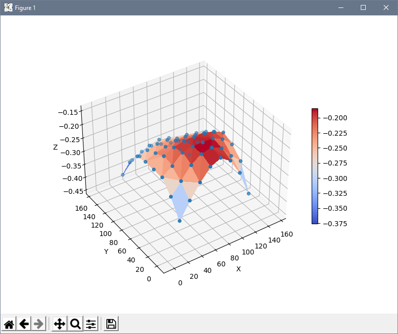
The post-processor reads in the output from the probing step and builds generates a B-Spline representation of the surface of the stock. It then reads in the OpenSBP NC code line by line. Each line is first checked against a list of supported features to ensure that the post-processor’s model of the machine is accurate. For example, the post-processor aborts the process if it detects the relative positioning mode being used or sees an unknown command.
Linear movement commands are parsed and rewritten based on a few rules while keeping track of the last known position of the machine:
- if both the current location and the target location are above the safe Z
plane (
z_fix_max), the command is output as-is and not further processed. - if the XY-distance between the target location and current location is bigger
than the maximum linear move distance (
max_dist), the move is split up into as many equidistant moves as necessary to make sure each sub-move is shorter thanmax_dist. Each of the sub-moves is processed as if it was a regular move command, and the original command is not output. - if the target Z is below the safe Z plane (
z_fix_max), it is adjusted based on the interpolated stock height at the target (X, Y) location.
Other OpenSBP features (comments, labels, and whitelisted commands) are output as-is.
milling
Since the surface data is relative to the zero-location used when probing, and the Z values are simply added to the existing values in the NC code, the resulting NC code already compensates for the initial zero that is usually necessary before milling. The processed NC code can therefore be run with the same tool and work coordinate system that the probing process was started with.