
Week 17. Mechanical Design - Machine Design
This week is machine week. It is a group assignment, but given the situation for the Covid-19 we are going to do it distributed. These are the requirements of the Document Assessment.
Mechanical Design
- Design a machine that includes mechanism + actuation + automation. ✔
- Build the mechanical parts and operate it manually. ✔
- Document the group project. ✔
- Document your individual contribution. ✔
Machine Design
- Actuate and automate your machine. ✔
- Document the group project. ✔
- Document your individual contribution. ✔
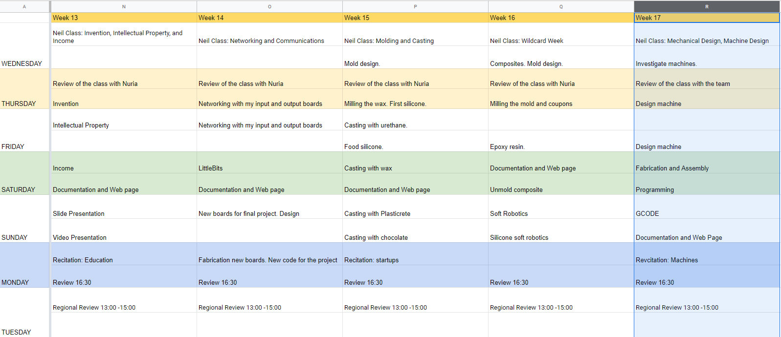
Like every week, my weekly schedule. 😊
Given the situation of the COVID-19, this year the construction and testing of the machine has been complicated. In this machine the working group is formed by Alvaro Macian (Cartagena), Lola Ojados (Cartagena), Ivan Gonzalez (Bilbao) and myself. As we cannot move around Spain, we have decided to manufacture the machine in León and they will help me remotely.
LE-CAR-BIL. Draw-Machine
Please visit our group website!!
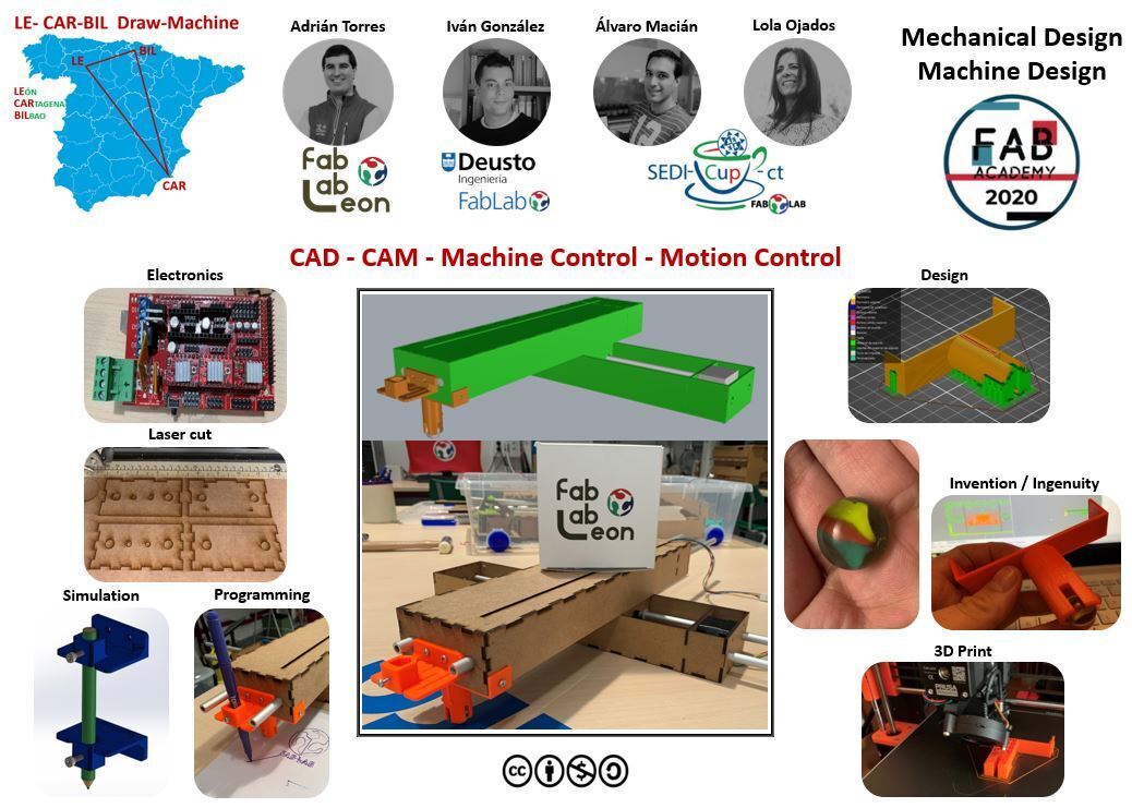
I am going to be in charge of the machine design, fabrication and assembly.
Mechanical Design
Jake Read Modules
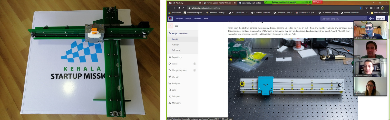
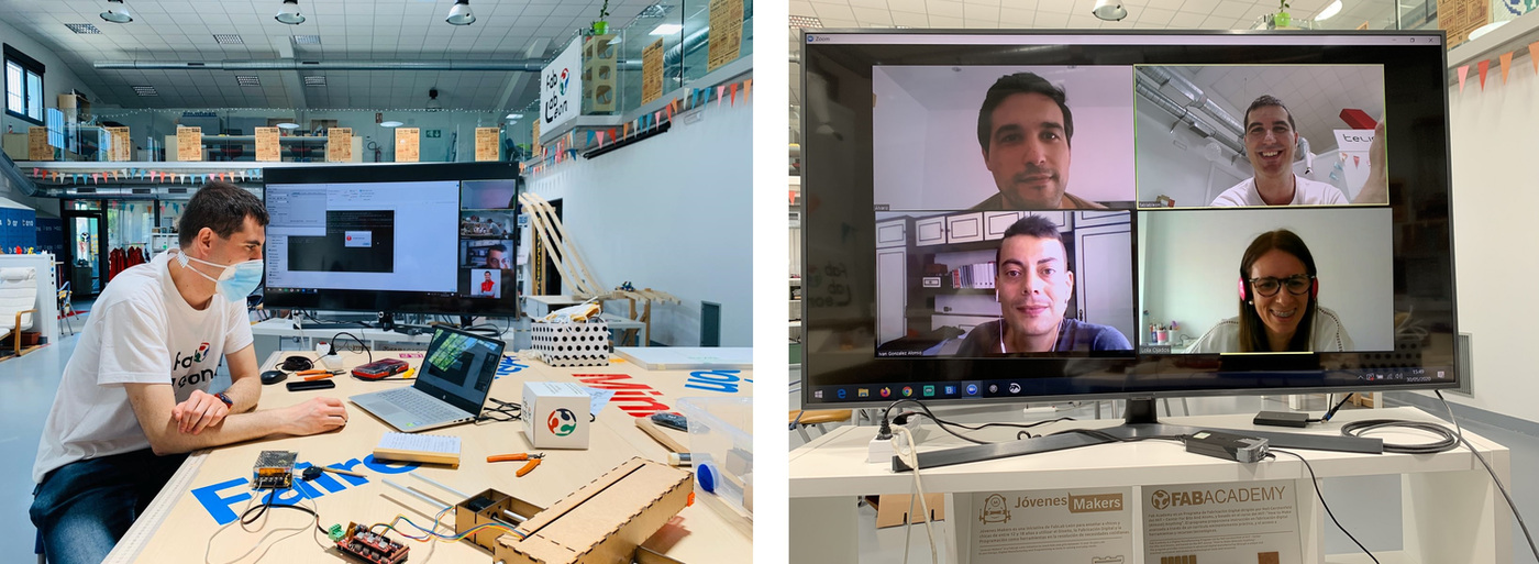
During the machine choice debate on Thursday, we decided to use Jake's modules, drawing inspiration from the work done by Pablo Nuñez, Epifanio Lorenzo, Yuichi Tamiya, Apeksha Bochare, Pradnya Shindekar at the Bootcamp in Kerala (India). An image of the videoconference, showing where the documentation is and how the machine will be.
Thanks to the documentation of my instructor Pablo Nuñez and the Jake Read repository, I begin to design the machine. In this case we are going to create a machine with two X and Y axes, like a plotter, in which the end effector can be something to paint.
Jake's modules are easy to manufacture because you only need three parts of the structure cut with the laser and assembled with small 3D printed parts. In Kerala they designed some legs, so that the module can be supported. In our case, this is the layout of the machine. Thanks to David Prieto (Fab Lab BCN), for converting the original Jake's from Rhinoceros 6 file to Rhinoceros 4.
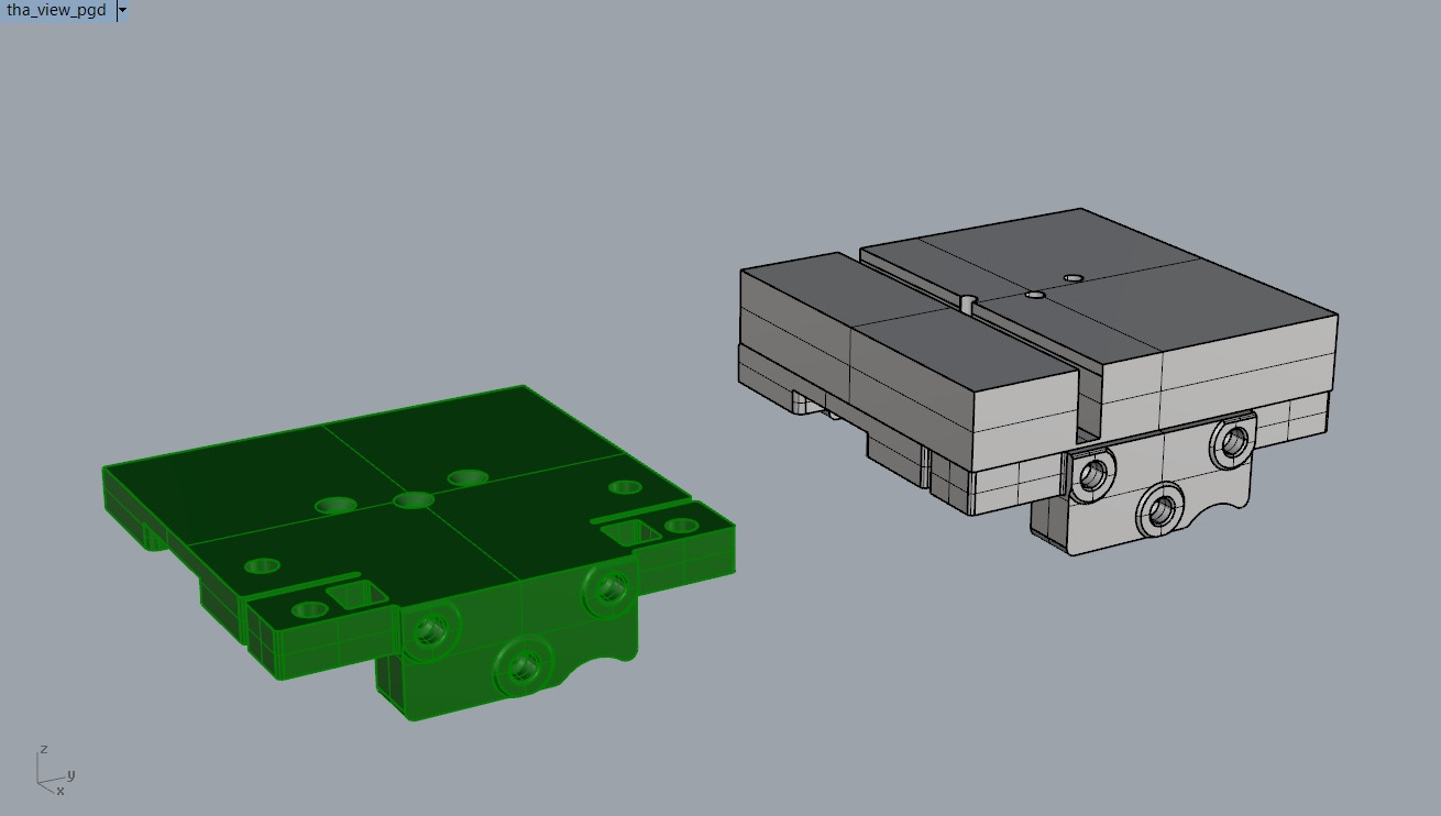
Modify the part of the slider, so that it can be connected to another module. The green piece is Jake's original, the gray is the modified one.
By making an inventory of the necessary parts in the Fab Lab León, we realize that we do not have the appropriate size bearings or the necessary inserts. We try to buy them, but they don't sell them in León. So it's time to change the plans. I inform the team.
Nadya Peek modules
Thank goodness that during the choice of the machine, we had an option B. And they are the use of Nadya Peek's modules. For several years the students of the Fab Academy of the Fab Lab León have used these modules.
For the creation of the X and Y axes to create a plotter, we were inspired by the machine they made at the Fab Lab Facens in 2017.
Thanks to Nadya Peek's MTM page, you can download the module designs. Also thanks to the documentation of the "Cintya" machine made by the Fab Lab León in 2019, I begin to design the different modules.
A module for the X axis, a module for the Y axis with a union connector for both axes.
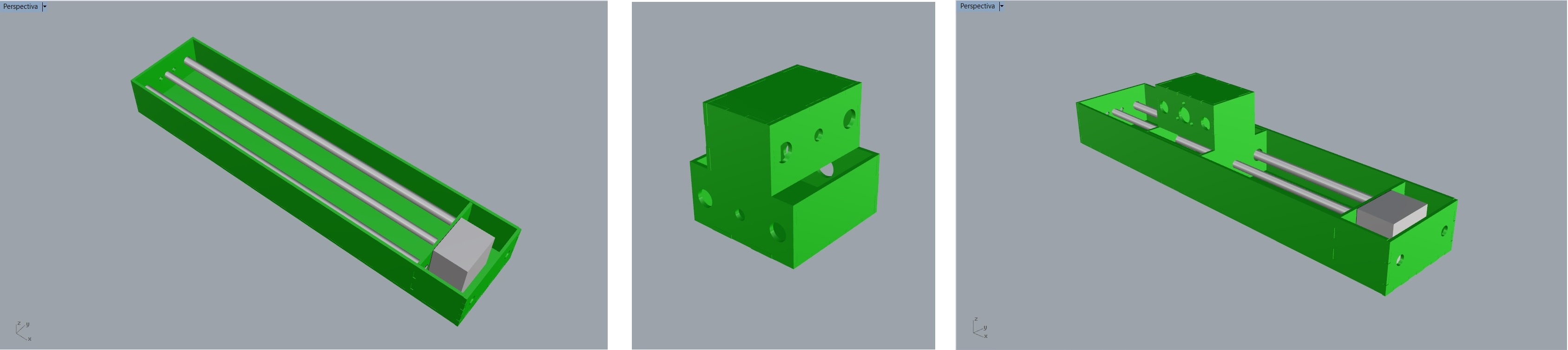
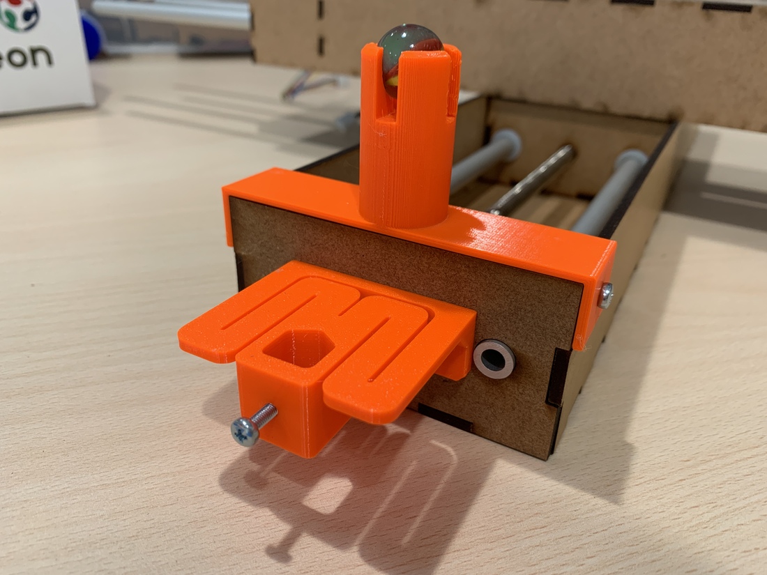
As the Y axis a part is in the air, to give it a mobile foothold, I design a marble holder inspired by the educational robot "Escornabot". Ivan sent me the design of the end effector, a holder to hold a pencil or a marker and I add it to the simulation.
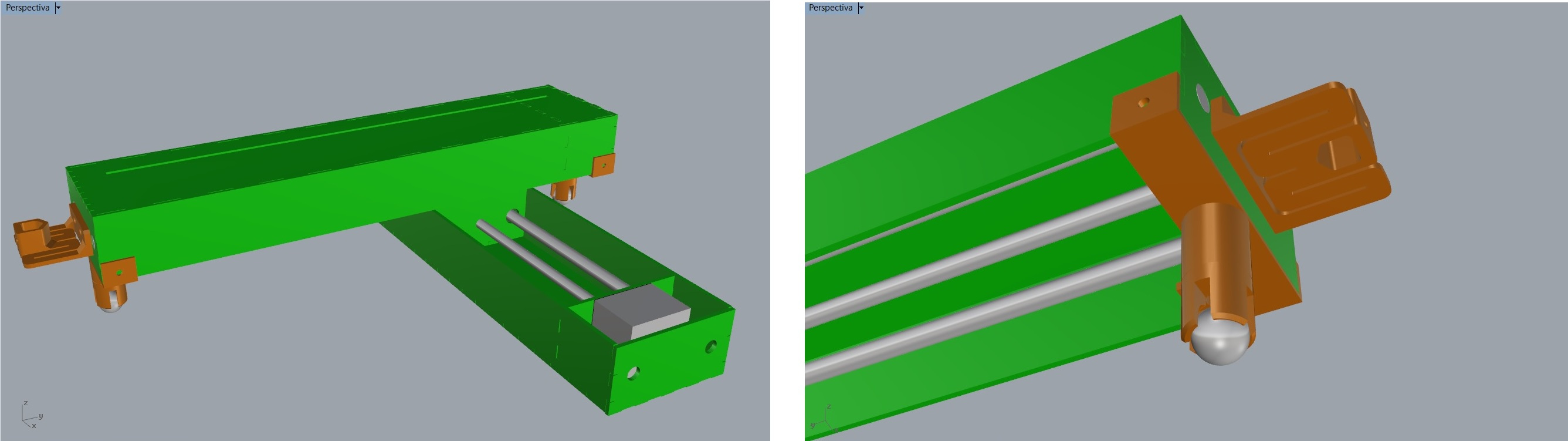
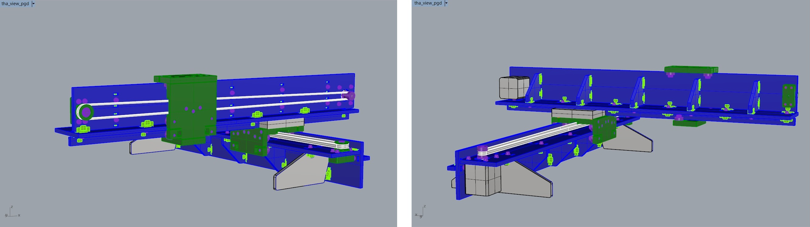
This is the 3D view of the machine.
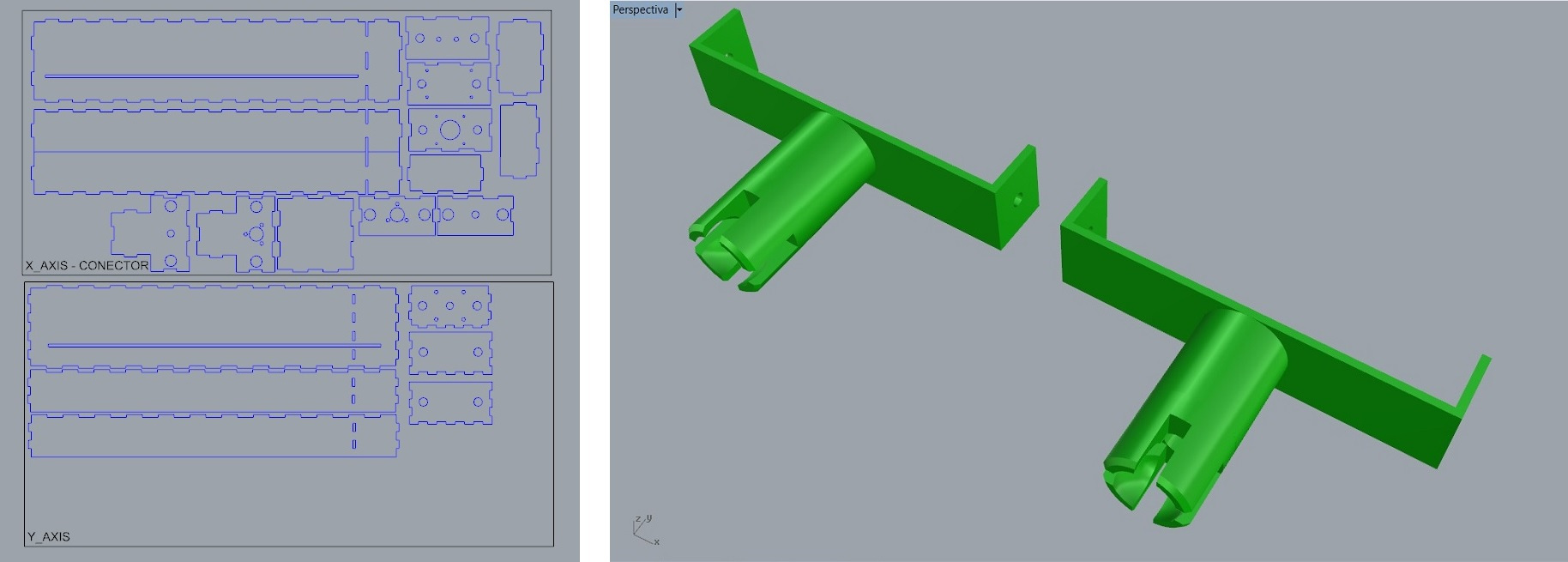
Once the simulation was done, I went on to create the exploded view of the machine to cut it in the laser and the support with the marble holder that will be 3D printed. At the bottom of the page you will find the files to download.
Fabrication and Assembly
The machine requires 3mm DM, two stepper motors with calibrated rod, four 9.5mm aluminum cylindrical guides, a PLA or PETG filament and two marbles.
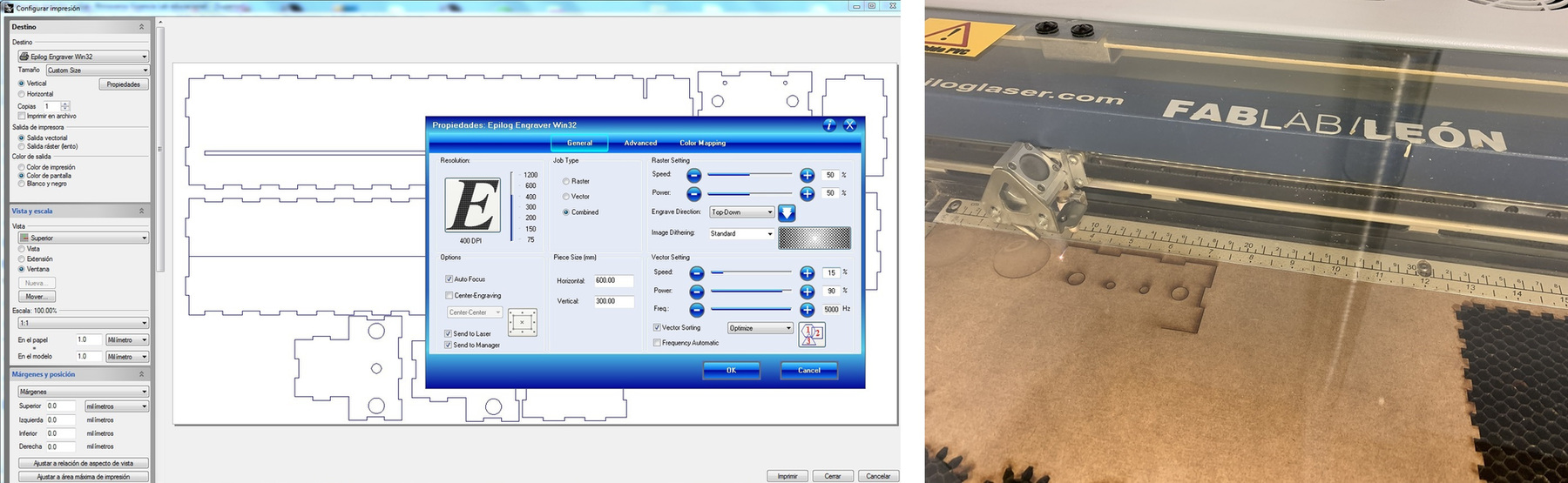
The first thing I will do is cut all the pieces with the laser cutter. The Fab Lab León laser cutter is 600 x 300 mm, so I have to use two 3 mm DM plates. The cutting parameters are Power: 90% / Speed: 15% / Frequency: 5000 Hz ppi 400
At the same time I print on PETG the supports with the marbles and the support of the tool that Ivan designed. The marble support, I put supports so that it makes perfect the accommodation of the marble.
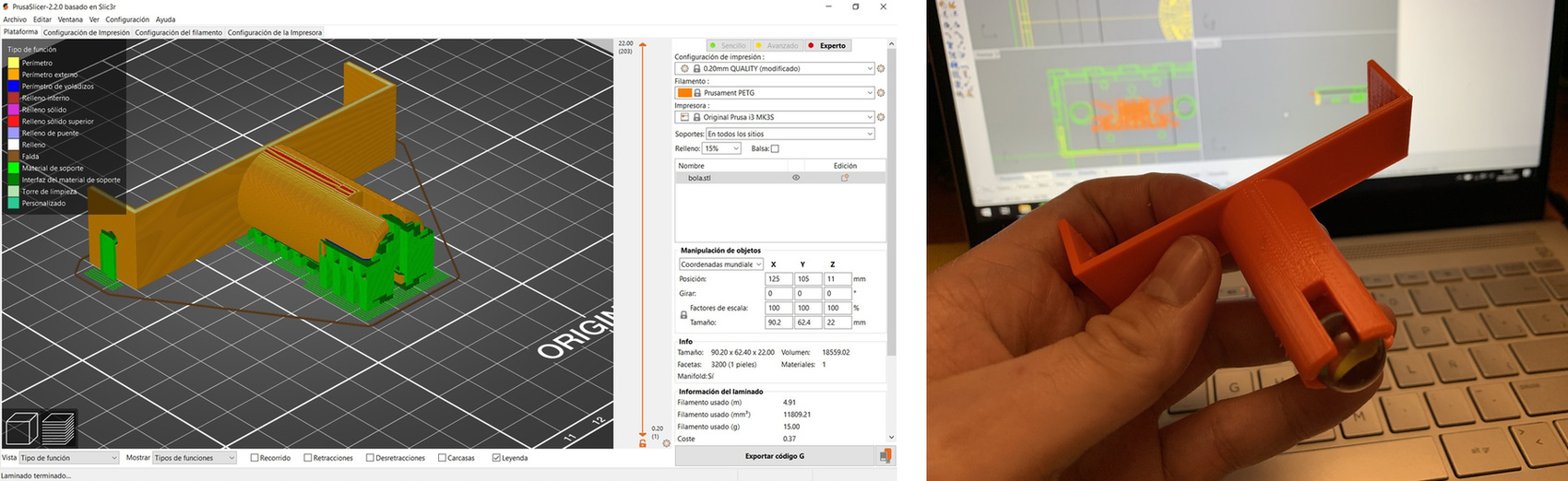
And this is the result of the movement of the marble, inside the support. It rolls and also has some slack to give us cushioning.
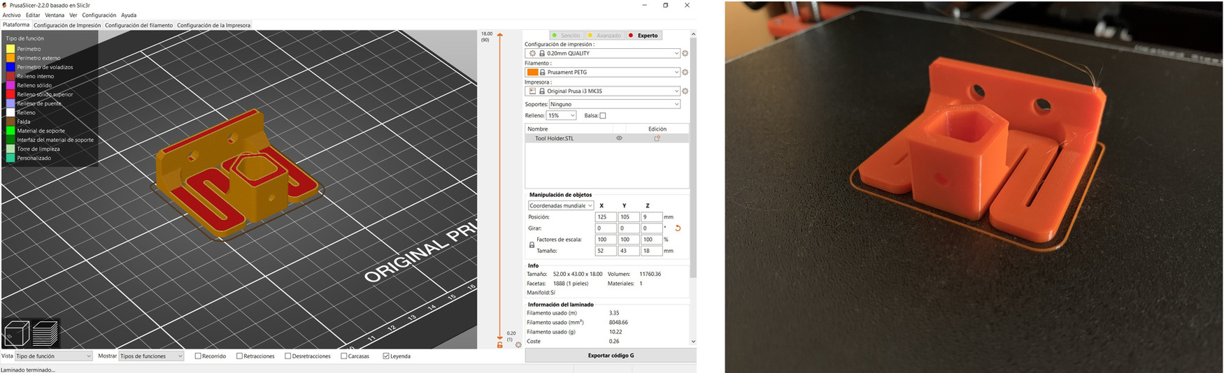
This is the support of the tool that Ivan designed and that transforms from "bits to atoms" thanks to the internet, from Bilbao to León.😀
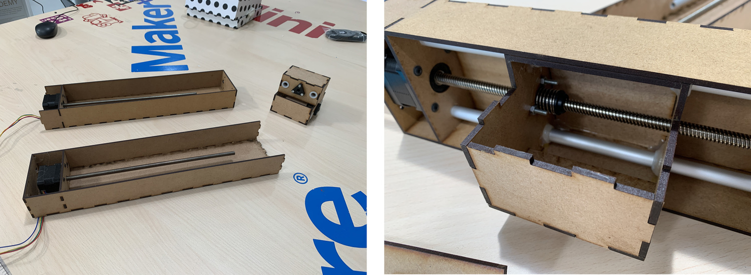
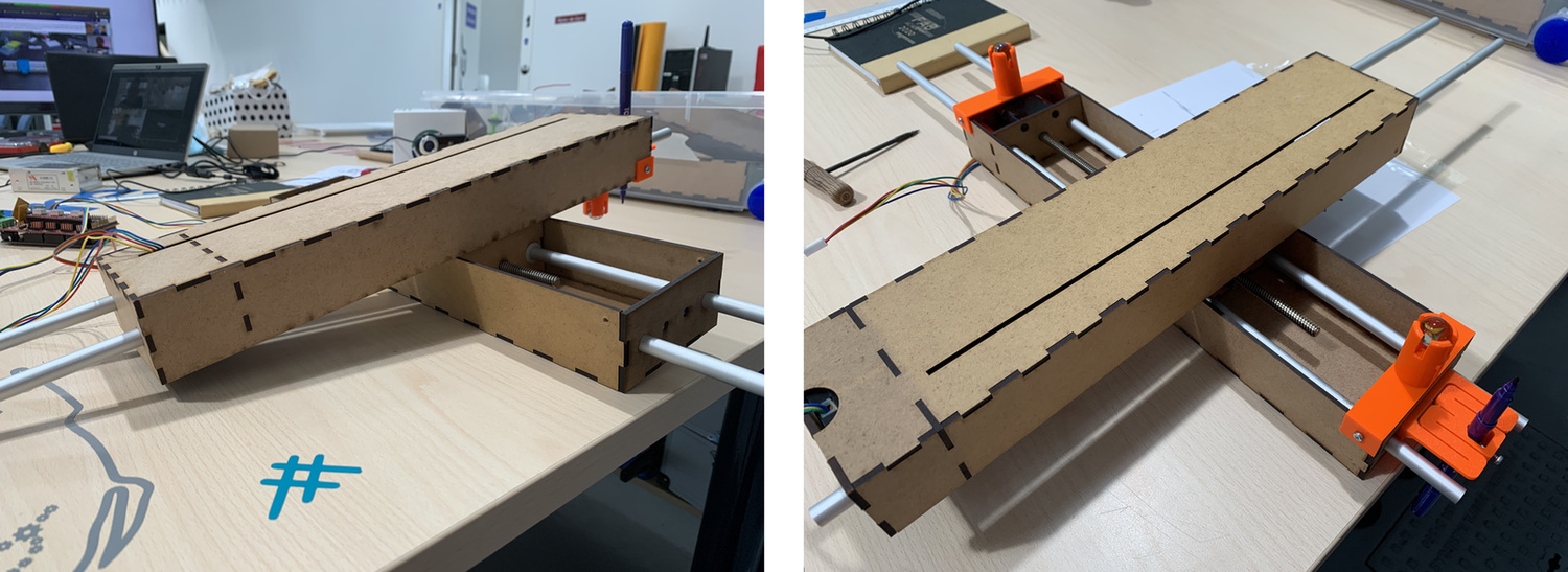
The next step is to assemble the Nadya modules cut with the laser and screw the steppers. To join the laser cut pieces, although they have pressfit, some pieces I assure with hot silicone and white glue. Make sure that the calibrated stepper rods fit snugly into the plastic inserts.
The next thing is to mount the support with the marble on the end of the machine and the support of the tool that Ivan designed. (I have to say that I made a mistake and mounted the opposite axis 🤣, nothing that cannot be solved by changing it in a moment).
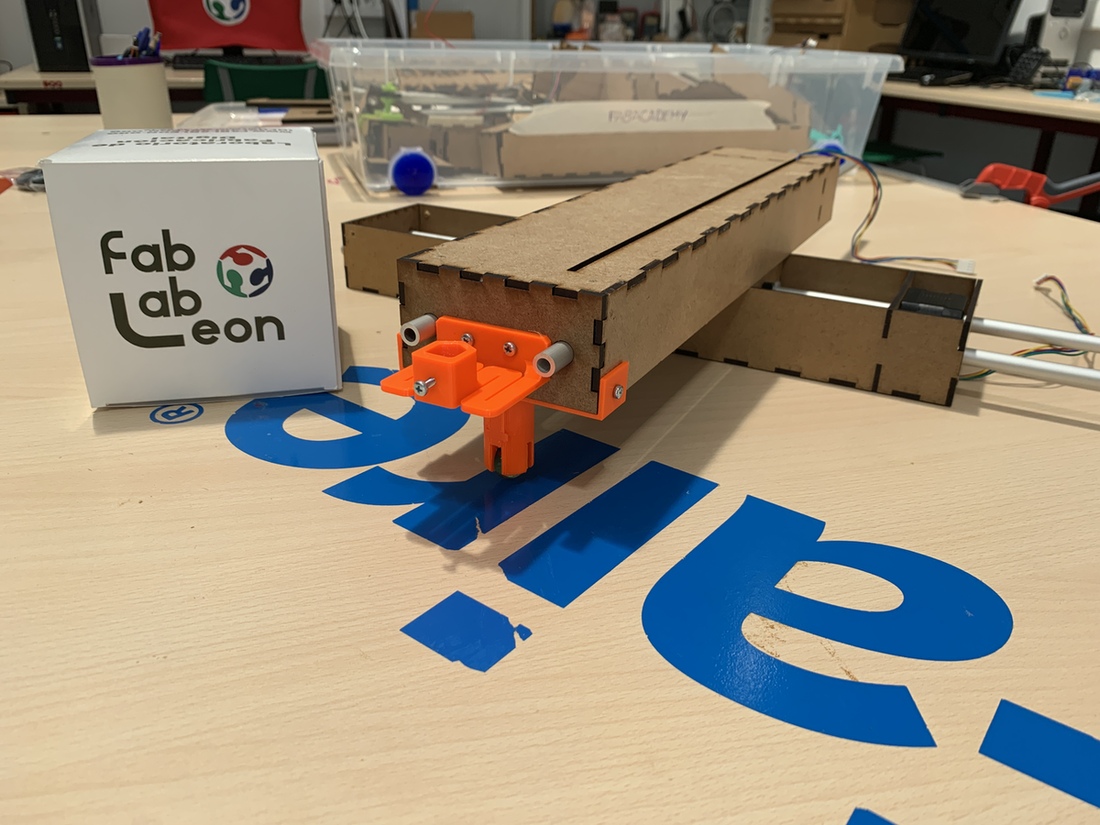
And this is the end result of the machine. 😍
Mechanical Movement: Operating it manually.
Once everything is ready, I try to move the two axes, each independently. Here is the sample video, and through the video conference of witness Alvaro, waiting to move on to the programming and electronic part. Thanks to Pablo my instructor who acted as camera director. 🤗
Electronics connection
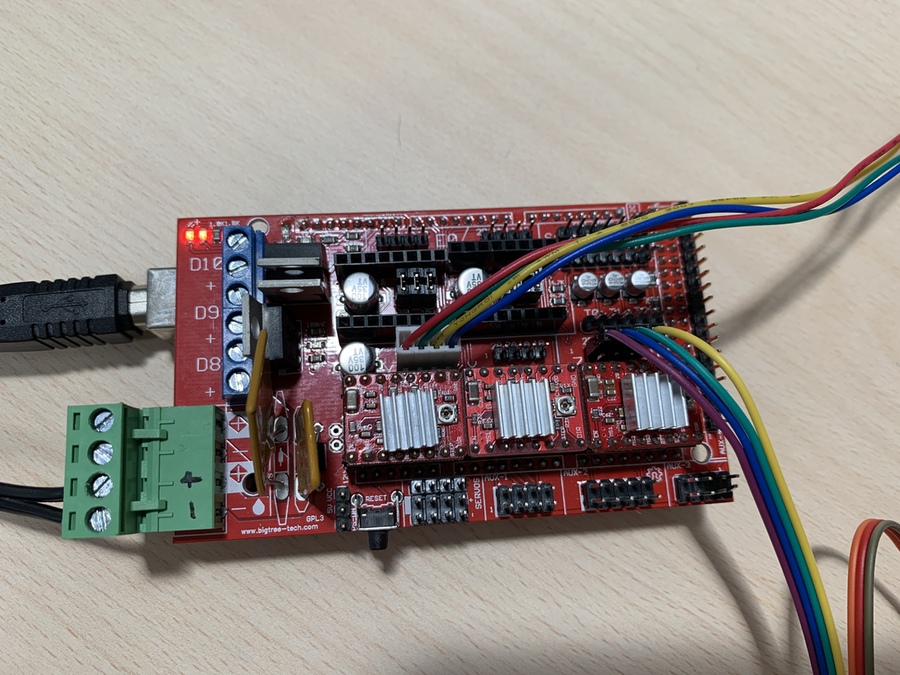
Once the Arduino Mega 2560 has been programmed (without connecting the RAMPS module); I connect the RAMPS where there are three Polulu Drivers (HR4988). We are only going to use two axes, in our case X and Y. By the GRBL software configuration, that connection is on the X axis and on the Z axis (this can be modified in the code). The RAMPS is powered by a 12V, 10A power supply. This is the physical connection.
Programming and generation of GCODE.
To know more information about this part please visit the group website or Alvaro Macian's webpage and Ivan Gonzalez 's webpage.
Updates
When we started testing the machine, we realized that sometimes the machine was "lame". The part of the tool was raised. So I printed another support with the marble and put it to the end.
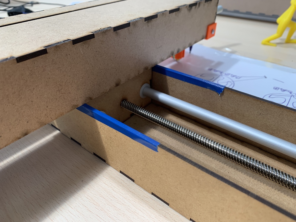
Another improvement, this is to avoid the noise caused by rubbing the two Nadya modules together. Pablo and I had the idea of putting some vinyl or tape on the profile and goodbye noises. 😅
Future of the machine ...
The machine was manufactured and configured in less than a week. It is something incredible, given the situation. 😊
But if we had more time, I would like to improve the end-effector. I would use a rack and pinion to raise and lower the marker and that would not mark the page, when it makes the trajectory in the air. I would also like to try using other tools, apart from the marker. Same as using a litter box and moving the sand with an awl, or marking the modeling clay.
Also, I have ordered all the necessary pieces to create Jake's modules this summer 🌞, in order to know and discover how these modules work and not stay with the desire to assemble them.
Conclusions
Given the situation and the moment we are going through all over the world, I am very proud of this team. 🤗
Thanks to videoconferencing and in real time, we have managed to assemble a machine, program it and have it draw something through a GCODE. It has been incredible; guys when all this happens and we can meet, we have to take a few beers to the health of the machine, LE-CAR-BIL.
Files
Find below the files that I made for this assignment.