4. Computer controlled cutting
This week I learned various methods of Cutting using Computer Controlled Machines. I learned the principles
Objectives
Learn Principles of Laser Cutting, Learn about the Various Laser Cutting Machines available and those in my lab Learn about Vinyl Cutting Machines Group Assignment - Learn How to use Laser Cutter, Learn machine parameters, Learn about Kerf and make kerf scales for various materials in our lab Individual Assignment 1- Cut a Cardboard Parametric Design on Laser, Cut a wooden object Individual Assignment 2- Learn How to use vinyl cutters using Mods Interface and Cut a design on vinyl sheet
Laser Cutting Terms
Laser cutting
This is the process of cutting a shape to create smaller sizes, pieces, or more complex shapes.
Laser engraving
Engraving is the process of removing a layer of a material to leave an engraving below. This is often used for etching barcodes onto items or personalising items.
Laser marking
Marking is similar to engraving in that a mark is made but the difference being that the mark is only surface level, while an engraving from laser engraving has much more depth.
Laser drilling
Drilling is the process of creating dents or thru-holes on or in the surface of a material.
Laser Cutting Parameters
Laser power, P
They can be set as a percentage between 0 and 100%. 100% is maximum power. For dark wood engravings or stamp engravings, you generally need high power, whereas low values are used for materials such as paper.
Cutting Speed, v
The Speed laser parameter describes the movement of the laser head. Fast speeds lead to short exposure times, slow speeds lead to long exposure times. For example, large-scale engravings of TroLase materials are engraved at high speeds between 80 and 100%, but for photo engravings with lots of detail on wood, the speed should not exceed 10%. This setting also affects the quality of the laser cut.
Number of Passes, n
The Pass parameter determines the number of engraving or cutting passes. With some materials, for example, it can be advantageous to engrave with lower power and high speed, and then repeat this process several times. This means that the material is less stressed per pass. For example, this approach is appropriate for a relief engraving.
Pulse frequency
As with the laser power, the pulse frequency can be matched to the relevant machining task. For example, it is recommended small contours are cut with reduced pulse frequency. The pulse frequency is also reduced when piercing in the ramp mode.
Our Laser Cutter
The laser cutter that is available in our FabLab is a Flexx trotec speedy 400. This laser cutter has two types of laser- CO2 and glass fibre laser. The laser cutter has two types of laser - CO2 and glass fibre laser. for our use we only need the CO2 laser. It has a 60 watt CO2 laser, 30 watt fiber laser, with a work area of maximum 610 mm by 305mm. In order to start working with it, we first turn on the laser cutter (the switch is clearly labeled), followed by also switching on the separate ventilation system. All of these can be seen in the images below. To interact with the laser cutter we used which is installed on the desktop that is next to the machine. Below I will list the general steps that have to be executed in order to laser cut a model or a piece.
The Flexx line of laser cutters has both CO2 and fiber laser technologies: The fiber laser enables us to engrave the copper layer of the FR1, and once it has been removed, we can cut the board with the CO2 laser.
Laser type: CO₂, Fiber or Flexx laser
Work area:610 x 305 up to 1016 x 610 mm
Max. workpiece height:125 - 305 mm
Laser power:10 - 120 watts
Things to be careful
The machine must not be left unattended while it is operating (supervised operation).
Switch off the machine at the main switch for periods of non-use.
Operate the machine described here only with a lens in place.
A missing lens may cause the unfocused laser beam to be reflected out of the housing.
Stop this machine immediately in case of failure.
When pressing an Emergency stop button, the electric circuit immediately shuts off.
The laser beam is interrupted, and all movements are stopped.
The function of the Emergency stop button is: Firstly: To prevent any risks to the operating personnel. Secondly: To avoid any damage to/destruction of the machine/material

Turn the Emergency stop button counterclockwise to unlock it (green marker is visible). 2. Reboot the laser system with the help of the key switch.
Adjusting Z axis
The beam that comes out of the end of the laser tube is actually quite wide, a 100W tube can make a spot size 5-10mm across if it shoots directly at a piece of material. This beam wouldn’t be very effective at cutting material so it needs to be focused down to a small spot. This increases the intensity of the beam at that exact location and allows it to vaporise the material as it traces out the shape of the work.
There is a lens in the cutting head of the laser that focuses the wide beam of the laser into a single spot point on the surface of the material. It’s at this focal point that the laser is most powerful, allowing you to cut through the material as fast as possible and with the smallest cut width. Everytime you change the material you need to refocus the laser beam so that this point is on the surface of the material.
How the laser is focused
There are actually two different ways of focusing the laser beam and they’re obvious really. Move the lens to the correct height above the material or move the material to the correct height below the lens.
Getting peak performance out of the laser cutter requires the same sort of careful adjustment of the Z axis
Ultimately, it’s a matter of focus. The laser is at its most powerful when its energy is concentrated into the smallest dot possible. That means there’s a “sweet spot” in front of the lens where cutting and engraving will be the most efficient; anything closer or farther away than that won’t be as effective.
The problem comes when you start cutting materials of different thicknesses. Just a few extra millimeters between the laser and your target material can have a big difference on how well it cuts or engraves. So the trick is maintaining that perfect distance every time you fire up the laser. But how?
One way to automate this process is a touch probe, which works much the same as it does on a 3D printer. The probe is used to find where the top of the material is, and the ideal distance can be calculated from that point. But in his experience, [Martin] has found these systems leave something to be desired. Not only do they add unnecessary weight to the head of the laser, but the smoke residue that collects on the touch probe seems to invariably mar whatever surface you’re working on with its greasy taps.
The best solution is actually the simplest. Just cut yourself a little height tool that’s precisely as long as your laser’s focal length. Before each job, stick the tool in between the laser head and the target to make sure you’re at the optimal height.
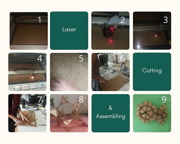
Designing for Laser Cutting
I was considering what to design using a laser cutter.
The requirement is to design a repetitive tiling pattern that should ultimately make a 3D-structure when joined together.
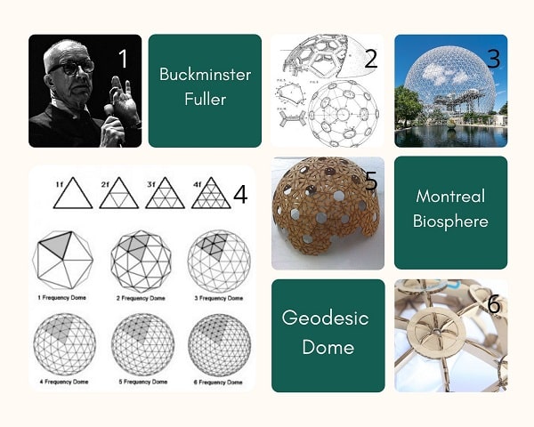
This reminded me of Buckminster Fuller’s Geodesic Dome at Expo 67, Montreal and I decided to use this as my reference. But first I designed some random shapes from which I fashioned a Bumble Bee Transformer shape on cardboard.
Geodesic Dome
Beneath apparently diverse natural phenomena lies a basic coordinate system that by applying that system to design problems strikingly simple solutions can be found. To describe that coordinate system BF evolved his synergetic energetic geometry, a mathematics which accommodates the requirements of many physical laws; this system gave him the mathematical basis of a geodesic construction. Scientists exploring other fields have found similar patterning.
Examples
Protein molecule model in an icosahedrom virus, Microscopic photograph of tissue from human eyeball, Algae photograph from Max Planck institute, Berlin
The patterning appears in very different kinds of natural phenomena. They are consciously articulated by Fuller in his Geodesic Structures.
Geodesic Dome Frequency
Nature is a very beautiful thing, very complex but simple. Because nature is made up of Pentagons and Hexagons which just happens to be made of triangles. The triangle is very strong and is the first shape known to man. When pressure is applied to a 30 degree angle cannot change the shape.
Pentagons are made of Isosceles triangles- 2 sides are equal and the base isn’t.
Hexagons are made of equilateral triangles and has all sides equal
When talking about domes, the definition of frequency refers to the number of pieces that each edge of the base figure is divided into in the process of triangulating its sides. For instance, we might start with a base figure of an icosahedron and divide each edge of each triangular face into 3 equal lengths. Those new points are connected to divide the original triangle into 9 smaller triangles. Since the original edges were divided into 3 parts, we call this a 3-frequency dome. The frequency is commonly abbreviated as “v”, so a 2-frequency dome is called 2v, 3-frequency is 3v, and so forth. The higher the frequency the more curved and sphere-like the dome appears.
Dome Calculator:
1. Desert Domes
2. Geo Dome
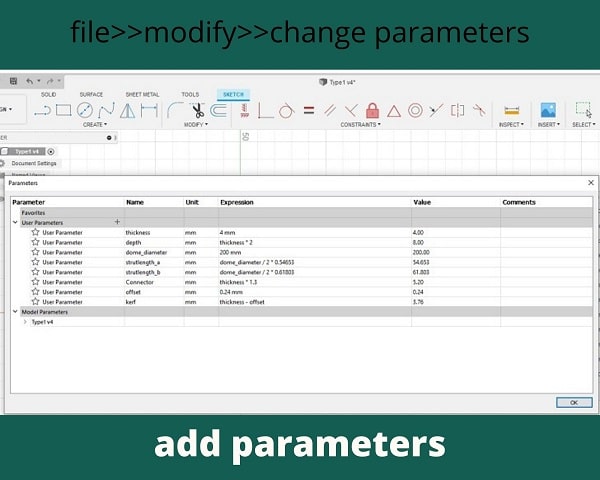
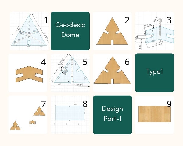
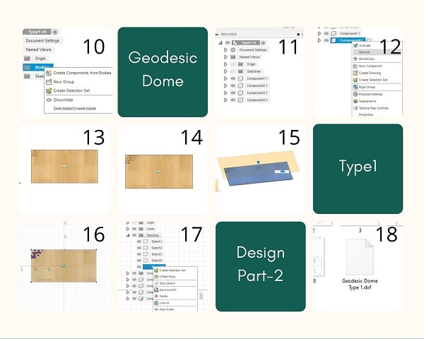
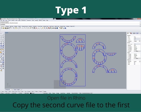
Design Type 1
For the first type I decided to follow a 2018 Fabacademy student Jun Kawahara’s documentation and do the same type of 2V Geodesic Dome.
2V type geodesic dome has two kinds of triangles. One is a regular triangle and the other is an isosceles triangle. The length of two sides of these triangles, A and B, can be calculated using this equation based on a given diameter.
A = diameter/2 * 0.54653
B = diameter/2 * 0.61803
There are two bending angles, 15.9 and 18.0 degree, which means two types of connectors have to be designed. I designed only one connector with a bending angle of 17 degrees (average of 15.9 and 18.0).
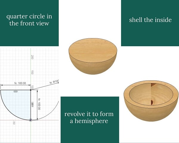
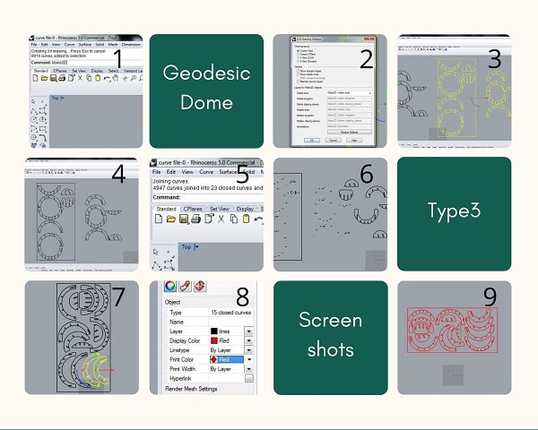
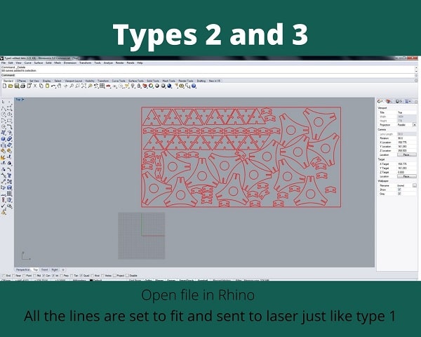
Design Type 2
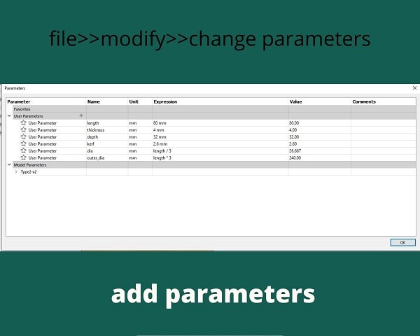
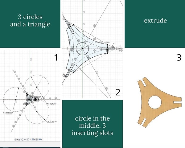
Design Type 3
All the .stl files were sent to the laser computer and opened on Rhino.
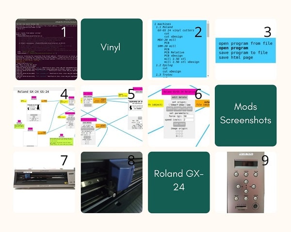
Vinyl Cutting
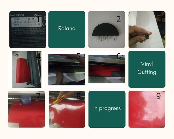
A vinyl cutter uses a computer-controlled blade to cut out shapes designed using vector graphics. In our lab,we have the Roland CAMM-1 Servo desktop vinyl cutter. It has a knife which is mounted on a CNC arrangement for linear motion. The knife can rotate on its axis and the bed has rollers for moving the sheet back and forth. The sheet is cut by moving the knife over it. We can set the cutting velocity and cutting force depending on the material of the sheet we are cutting.
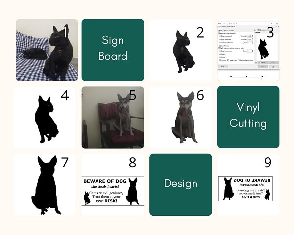
I decided to make a “Beware of dog” sign for the gate in my house.
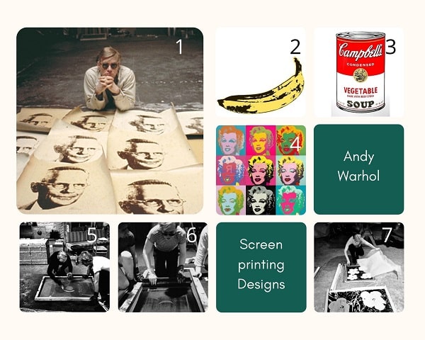
Since it is meant for outside the house, I thought it might be better if I use the vinyl to make a silkscreen and then screenprint the image. I was thinking of Andy Warhol’s works while doing this.
Andy Warhol
Andy Warhol portfolio Andy Warhol screenprinting technique
Designing for Vinyl Cutting
Step 1: I used the outline from the pictures of Padmini, the dog and Pumba, the cat to make a creative design. But the image is raster so I needed to make it a vector. I used inkscape to make it a vector by using the Trace Bitmap Tool.
Step 2:
The creative:
Fab Mods Settings for Vinyl Cutting
Diameter(mm) =
Overlap =
Offsets =
Error(pixels) =
Intensity =
Force =
Velocity =
Working of Vinyl Cutting Machine
Step 1: First release the pressure plate by pressing the handle on the left side. for inserting the sheet and Load the sheet from the back.
Step 2: Slide the pressure rollers to where the sheet is placed, making sure that the rollers stay inside the white lines.Pull up the pressure plate handle to lock the sheet in place.
Step 3: Turn on the machine, the tool head will move to the home position.
Step 4: Select the type of sheet (Roll or Peice), click enter
Step 5: The machine will automatically move the tool head to the left position of the roller, and give you the width and height of the sheet that is loaded.
Cutting
Step 1: In here i used a roll of vinyl sticker so i selected Roll from the Roland Menu
Step 2: Roland will automatically scale the vinyl roll.
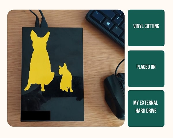
Step 3: we can see the slice and we need to remove the unwanted portion from the sheet. (To screenprint I followed the steps given separately underneath and the following three steps are what I did to stick the vinyl on to a wooden piece directly.)
Step 4: Now we got the parts only we need, so next we need to get the sticker from base plastic, for this we are using masking tape
Step 5: when we remove the masking tape we will also remove the sticker from base plastic and we got this.
Step 6: Next, we place the sticker.
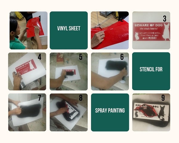
Spray Painting using Vinyl
Step 1: For spray painting I prepared the vinyl sticker. I removed all the pieces of the design that needed to be seen.
Step 2: I pasted the vinyl sticker on to a sun board
Step 3: I used the spray can and painted over the whole area
Step 4: I removed the vinyl to reveal the painting
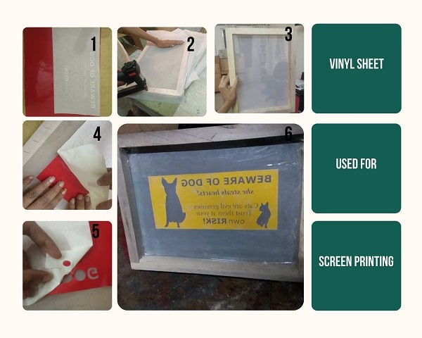
Screen Printing using Vinyl
Step 1: For screen printing I prepared the vinyl sticker. I removed all the pieces of the design that needed to be printed on to the acrylic sheet.
Step 2: I applied the transfer tape on to the design side of the vinyl. Now the design is sandwiched between the sticking side and masking tape.
Step 3: I bought a wooden frame that can fit the vinyl design inside.
Step 4: I took a piece of silk screen fabric and stapled one side of it. Then I pulled the fabric tight with maximum tension so as to avoid any sagging of the cloth and stapled it to the other three sides.
Step 5: I removed the vinyl sticker and transferred the vinyl on to the screen. I used a metal squeegee to remove any air bubbles present.
Step 6: I removed the transfer tape carefully. But it was spoiled as the transfer tape had excess gum on it. So I removed the Vinyl from the silk screen, cut vinyl again but before placing it on the Transfer tape I removed the excess gum by repeatedely sticking and removing on a clean table.
Step 7:I taped all the exposed areas on the screen other than the required design.
Step 8: I centered the design on the sheet to which the design needs to be applied
Step 9: I added the paint to the screen, and squeegeed it over the screen so that the thin layer of paint would bleed through the silk fabric on to the acrylic sheet creating the design.
Files
All my files are here: