Week 4. computer-controlled cutting
Assignment
- group assignment: characterize your lasercutter, making test part(s) that vary cutting settings and dimensions
- individual assignment: cut something on the vinylcutter; design, lasercut, and document a parametric press-fit construction kit, accounting for the lasercutter kerf, which can be assembled in multiple ways
group assignment
see FabLab Kamakura's group assignment page.
press-fit construction kit
what I am going to make
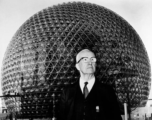
Fullerene(C60) is a soccer ball-like chemical molecule, which is also called Buckminsterfullerene. Then name, Buckminsterfullerene, was named after Buckminster Fuller, architect, systems theorist, author, designer, and inventor because its geodesic structure resembles his geodesic dome.
There were already some parametric designs for a geodesic dome (here and there). However, I wanted to design it by myself.
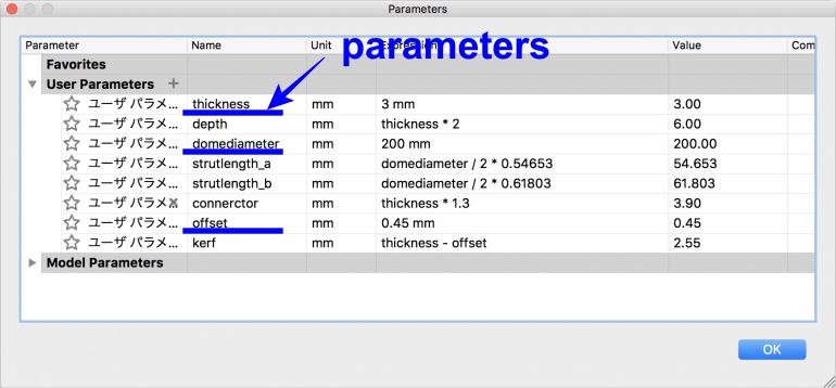
For a parametric design, I used three parameters which are "the thickness of cardboard," "a laser offset value" and a "dome diameter." Other values, such as a kerf, the depth of a kerf and the length of two sides of triangles are dependent on three parameters. I can change the value of these parameters in Fusion 360 (parameter window) which I'll explain later.
rough sketch
In our group assignment, we used 3 mm thickness cardboard, and laser offset value was 0.45 mm. In addition to accounting for these parameters, I also made a dome diameter a parameter of design.
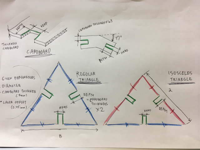
There are various types of domes, and I chose to design 2V type. 2V type geodesic dome comprises two kinds of triangles. One is a regular triangle (BBB) and the other is an isosceles triangle (AAB). The length of two sides of these triangles, A and B, can be calculated following equation based on a given diameter.
A = diameter/2 * 0.54653
B = diameter/2 * 0.61803
There are two bending angles, 15.9 and 18.0 degree, which means I have to design two type connectors. I thought the difference of angle was negligible for a small dome then I designed only one connector with bending angle of 17 degrees (average of 15.9 and 18.0).
The rough sketches of triangles and connector I have to design parametrically are shown below.
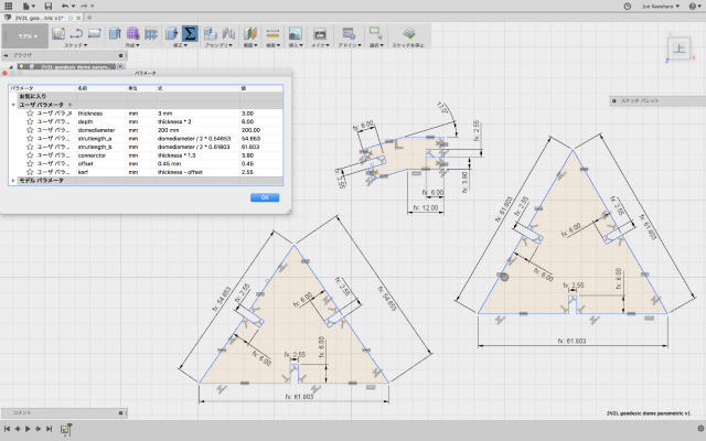
sketchs on Fusion 360
I chose Fusion 360 for parametric deisign and used many constraints.
In Fusion 360, if you select [MODIFY]>[Change parameters], parameter window pops up. I can design a dome parametrically by modifying three parameters here, "thickness" = the thickness of cardboard, "offset" = a laser offset value and "domediameter" = dome diameter.
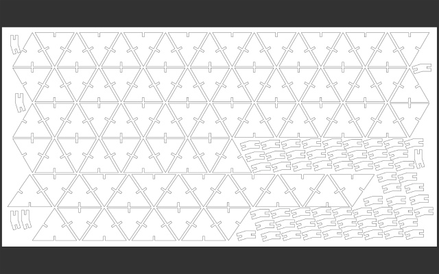
After finishing a design, I exported it as a dxf file and open it with illustrator and panelized the construction kit.
lasercutting
Lasercutting equipment in FabLab Kamakura is TROTEC Speedy 100.
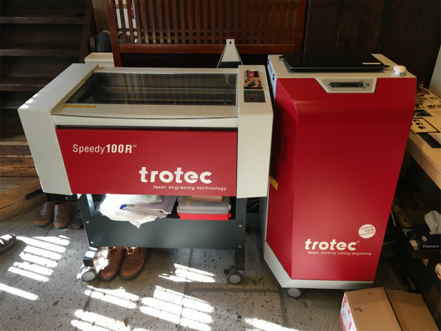
Standard cutting settings are followings.
power: 70
speed: 1.0
frequency: 1000 Hz
I placed cardboard on cutting table (honeycomb table) with masking tapes at four corners, but it was not enough to hold a cardboard level. The laser was out of focus especially right side of a working area, cutting lines were dull, and the surface was charcoaled a lot. I also mistook a length of side of a regular triangle.
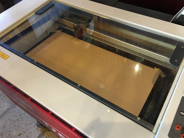
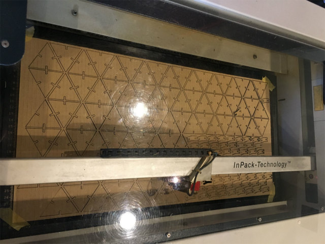
I modified parameters and cut again (pdf). In this trial, I placed a cardboard firmly on the cutting table with much more masking tapes.
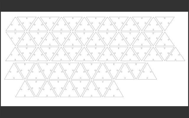
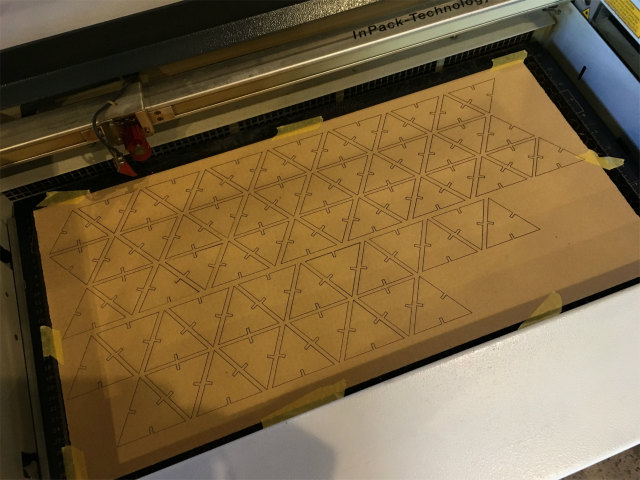
I have lasercut acrylic plate and wood before, but this is my first cardboard lasercutting. I didn't know there were charcoals on parts and my hands got dirty during my assembly. There weren't enough connectors, but I assembled almost five-eighth dome.
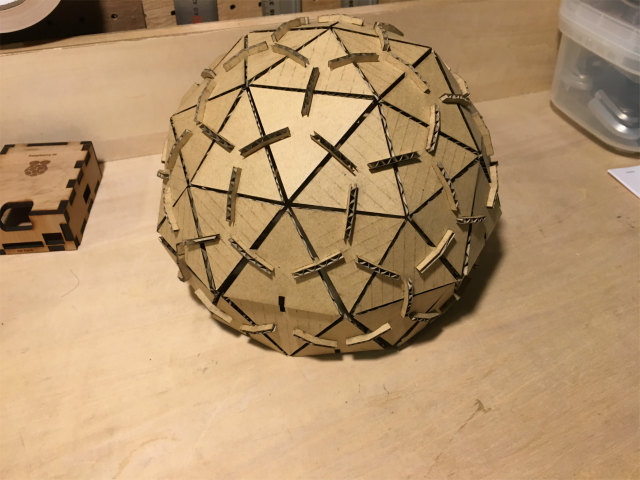
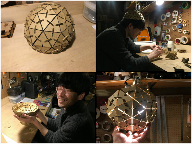
The dome can be a hat, bowl and a lump shade.
vinyl cutting
stickers
I want to create my original stickers in this assignment. Sticker design is from my final project sketch.
machine settings and cutting
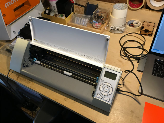
I used Silhouette CAMEO to cut a sheet of sticker paper. I downloaded and install Silhouette Studio which works with Silhouette CAMEO.
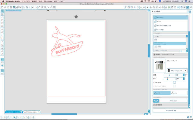
As Silhouette Studio need a design file of dxf format, I exported illustrator file(.ai) as dxf format (AutoCAD ver. R13/LT95), but Studio couldn't import it. There were some reasons for this error.
- an image was in a layer
- text characters were not outlined
- paths were not compounded
After I modified them, I could import dxf file into Studio.
I modified the image size, its position and selected a recommended settings for a silhouette vinyl. These are followings.
- media type: Silhouette vinyl
- blade length: 2
- speed: 5 cm/s
- thickness: 10
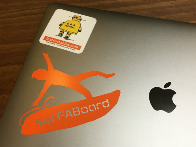
I scratched off unwanted parts and applied to a transfer paper, and then I transferred a logo sticker on my laptop.
files
pressfit kit
2V geodesic dome: fusion 360 format (.f3d)
2V geodesic dome: drawing exchange format (.dxf)
vinyl cutter
surFABoard logo: drawing exchange format (.dxf)
surFABoard logo: illustrator format (.ai)