
|

| Sukkur IBA University Merit, Quality, Excellence |
Principles and Practices
Idea
This assignment is all about brainstorming project management concepts. I began with various concepts such as a drone, a smart lighting system for the house, a smart camera sliding tripod, and so on. Now I'll start working on the Smart Lock system. On paper, I doodle a rough sketch of my concept. Sketching on paper is a valuable and essential part of the design process.
SKETCH
Before I can make the sketch, I need to design the size of the door as well as the size of the electronic devices I'll be using.
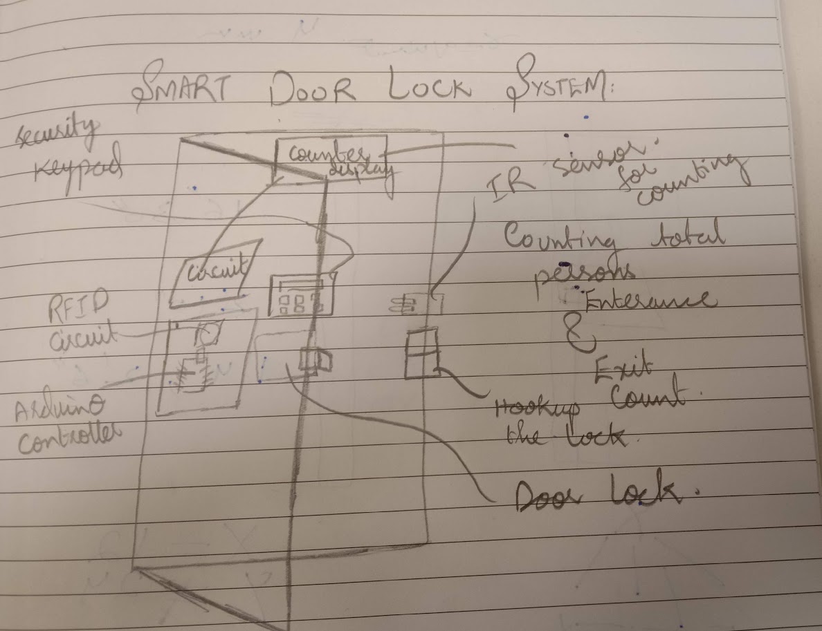
I am going to make RFID based door lock that can be open by using a Radiofrequency identity card(RFID) and I am going to put also keypad lock so that person who doesn't have an RFID card who has access to open the door by using the passcode. The reason behind this idea is that to secure the room from unwanted people.
The door opens as soon as we place the right RFID card in close proximity to the reader. It will remain open for a brief period of time before closing again. Assume, however, that an individual entered using the correct tag and now wishes to exit. This could be accomplished by installing another RFID module on the inside.
How Does IT Work?
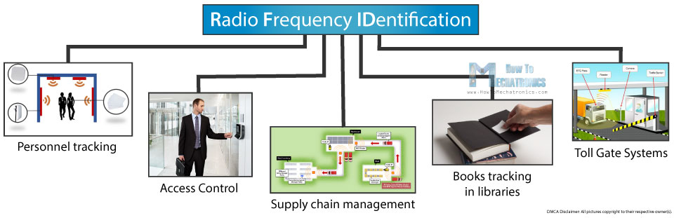
RFID stands for Radio Frequency IDentification, and it's a non-contact device that's widely used in a variety of industries for things like staff monitoring, access control, supply chain management, library book tracking, tollgate systems, and more.
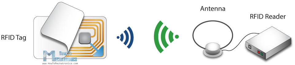
An RFID system consists of two main components, a transponder or a tag which is located on the object that we want to be identified, and a transceiver or a reader.
The RFID reader consist of a radio frequency module, a control unit and an antenna coil which generates high frequency electromagnetic field. On the other hand, the tag is usually a passive component, which consist of just an antenna and an electronic microchip, so when it gets near the electromagnetic field of the transceiver, due to induction, a voltage is generated in its antenna coil and this voltage serves as power for the microchip.
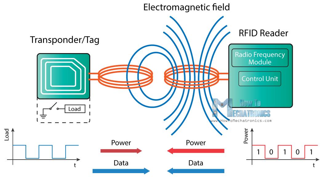
Now as the tag is powered it can extract the transmitted message from the reader, and for sending message back to the reader, it uses a technique called load manipulation. Switching on and off a load at the antenna of the tag will affect the power consumption of the reader’s antenna which can be measured as voltage drop. This changes in the voltage will be captured as ones and zeros and that the way the data is transferred from the tag to the reader.
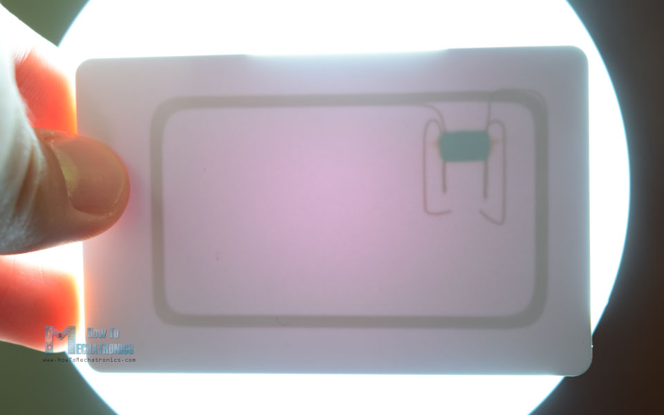
These tags have 1kb of memory and have a microchip that can do arithmetic operations. Their operating frequency is 13.56 MHz and the operating distance is up to 10 cm depending on the geometry of antenna. If we bring one of these tags in front of a light source we can notice the antenna and the microchip that we previously talked about.
I'm counting people via two IR sensors to see how many people are in the room and see how many are vacant available, and this will show on the outside of the door, so a seven-segment monitor will be used. However, this is just my perspective, It can be modified by the requirement.
Input Devices
RFID Card , Keypad , IR Sensors
Output Devices
Seven segment display, Door Lock
Process
In my project, I'll use an Arduino as the controller, which will be connected to RFID, a keypad, and infrared sensors to detect people crossing the door, with the results displayed on a seven-segment monitor.
Weekly Distribution
2D designing and laser cuting:-The Box of the circuit is the base of press fit.
3D designing and Printing:- 3D designing and printing of sensors holders and Seven segment holders.
Electronics Production:-Generating .rml files from mods, milling using SRM-20, and soldering components.
Electronics desinging:- Designing the controller.