
Assignment
- To design the in-circuit programmer (ISP) by milling the PCB.
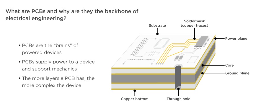
Introduction about PCB
Electronic circuits in engineering and industry are normally manufactured by using printed circuit boards (PCBs). These boards are made up of special materials that do not conduct electricity such as fiber and glass. The circuits are designed on the boards with copper tracks instead of wires for the conduction of electricity between the electronic components.
GROUP ASSIGNMENT: CHARACTERIZE THE DESIGN RULES OF YOUR PCB PRODUCTION PROCESS
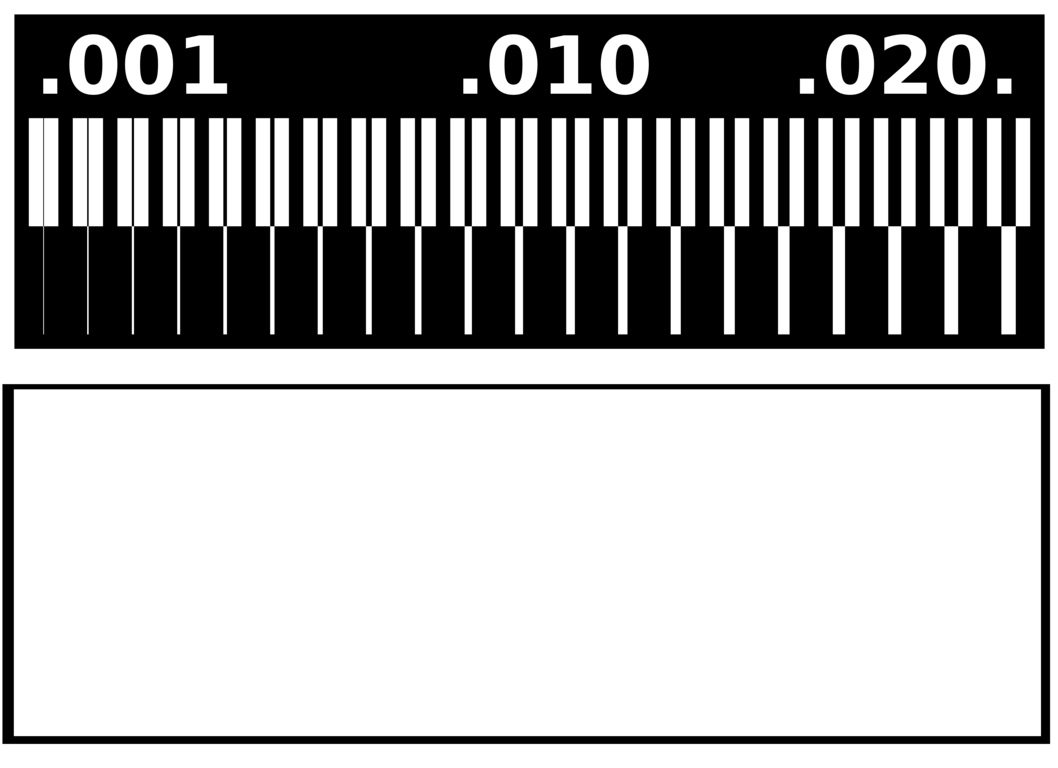
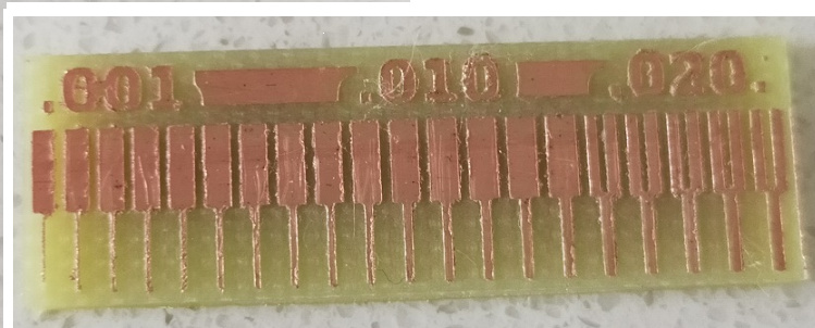
In this week ,we have Learn about PCB fabrication and milling. We have Choose to work on SRM 20 machine for PCB Milling. So we had to charcterize the design rules like what minimum distance in-between traces can be detected by PCB milling machine or not , and what effect does the width of trace posses while Milling. Below is attached the board we made as a group assignment. We found it in fab academy weekly notes.
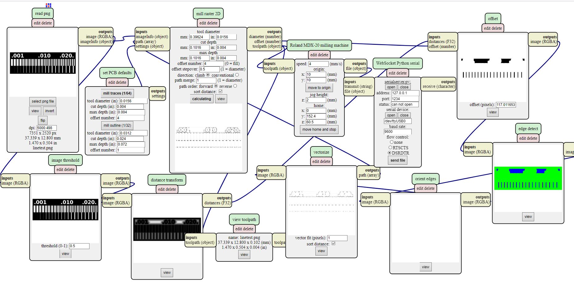
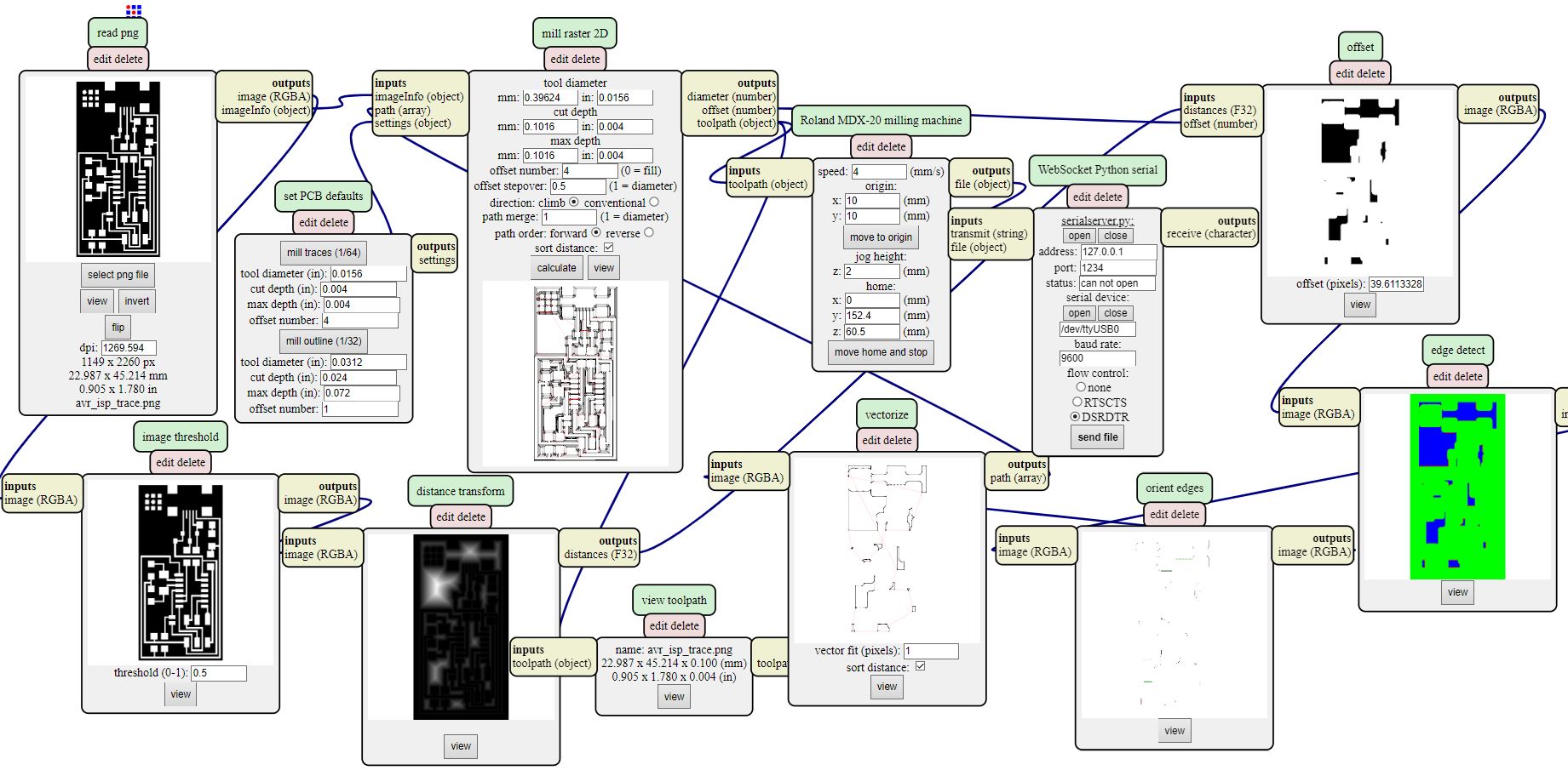
Generate the RML files by using Mods
There are few steps for generating RML files.
- Open the mods.cba.mit.edu
- Right click on Mods Icon
- Go to the Programs open to the Open Server Program
- Choose the Roland SRM-20 PCB-PNG.
- For Saving the rml File we Removed the Web Socket Device and the Save file.
- Right click on the Mods Space and Open the Module, Open Server Module, Select and the File Save.
-
- Soldering Iron
- Soldering wire
- Tweezer
- make clean
- make hex
- make fuse
- make program
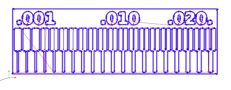
Image Show that How to Use the Mods for Generating the rml
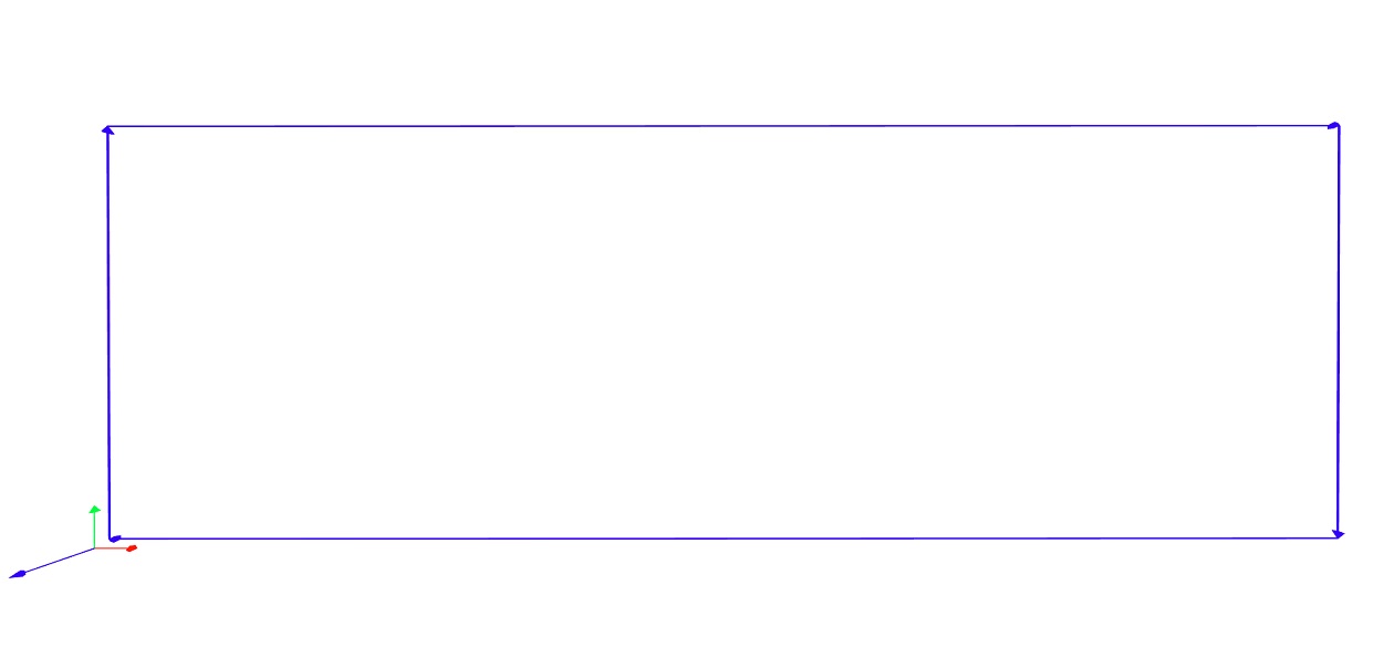
Outer of the Test Board
Generated RMl File
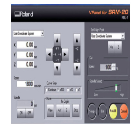
Now Open the SRM-20 Machine
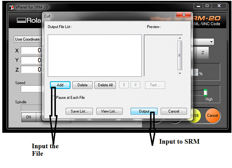
For Milling with Roland SRM-20 we are using VPanel software, it has a direct wired connection with the machine. Following image shows the GUI of this software.
Set the Origin x, y,z (0,0,0) Milling the Trace and set the Bit(1/64) and for Outer (1/32)
Put the Trace File for the Milling
Click Cut on the control panel. the Add the File for the Milling
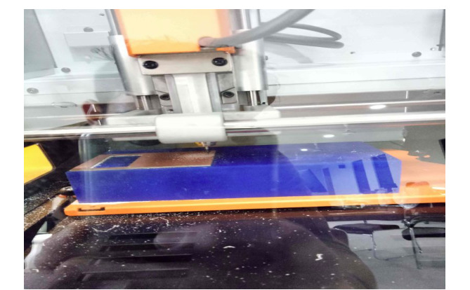
While Milling the Of Test file
After the complete traces Put the Outer File using Same Process
Test File After Milling
Individual Assignment: Make an in-system programmer(ISP) by milling the PCB using ATTINY-44
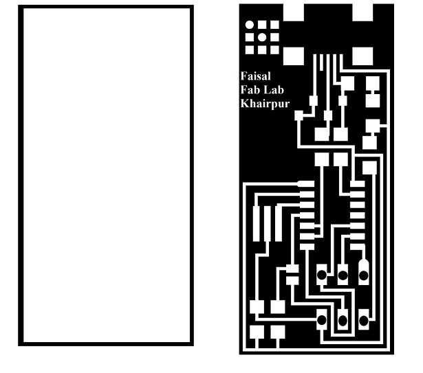
PCB ISP Programmer PNG file are taken from the Fab Academy 2020
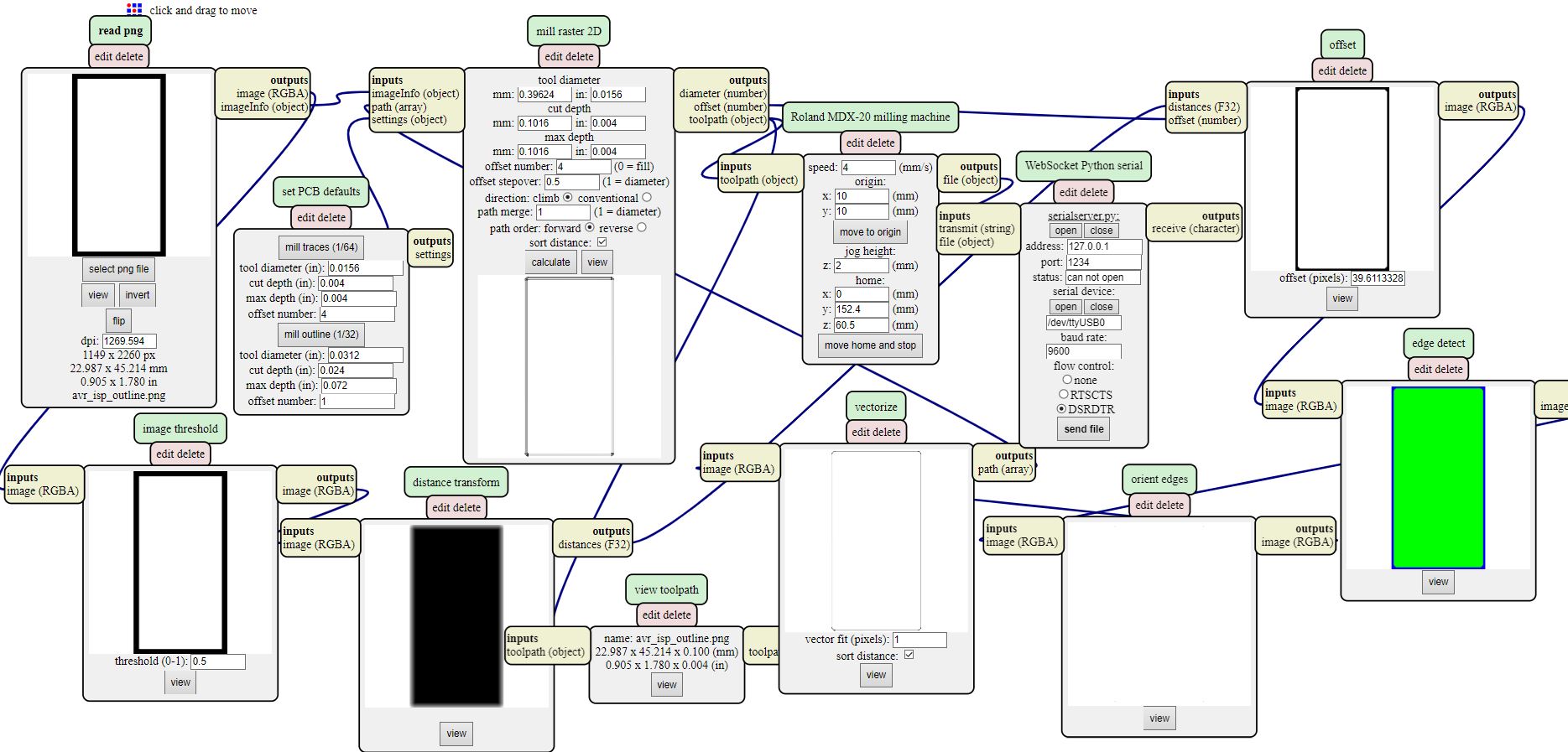
Generate RML files for ISP Programmer ATTINY-44
As we already have milled the PCB layout of Test File. So now We repeat same Process, for milling The ISP Programmer. so, we need RML files. we can generateRML files using HERE .
Outer layer Of ISP Programmer
RML File of the ISP Programmer
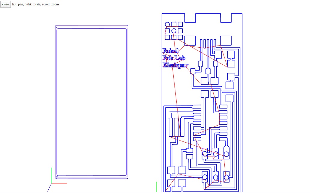
Now I want to Mill the ISP Programme USING SRM-20 Machine
So First Replace the old PCB Board with New PCB Board
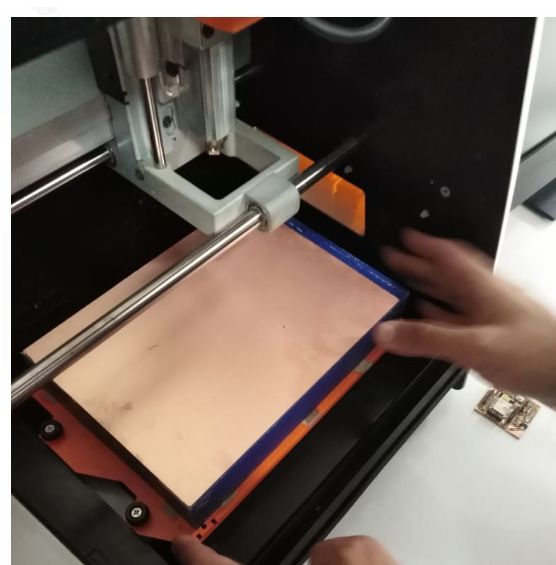
Same Proccess Test file Milling is Repeat for ISP Programer. the Final result Of ISP Programmer :
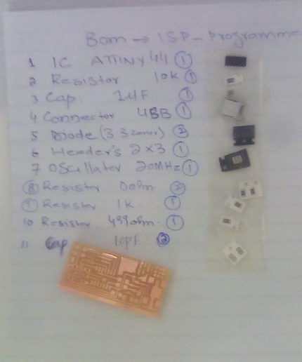
There are some soldering tools I used to solder my PCB Programmer ISP.
while Soldering the Circuit
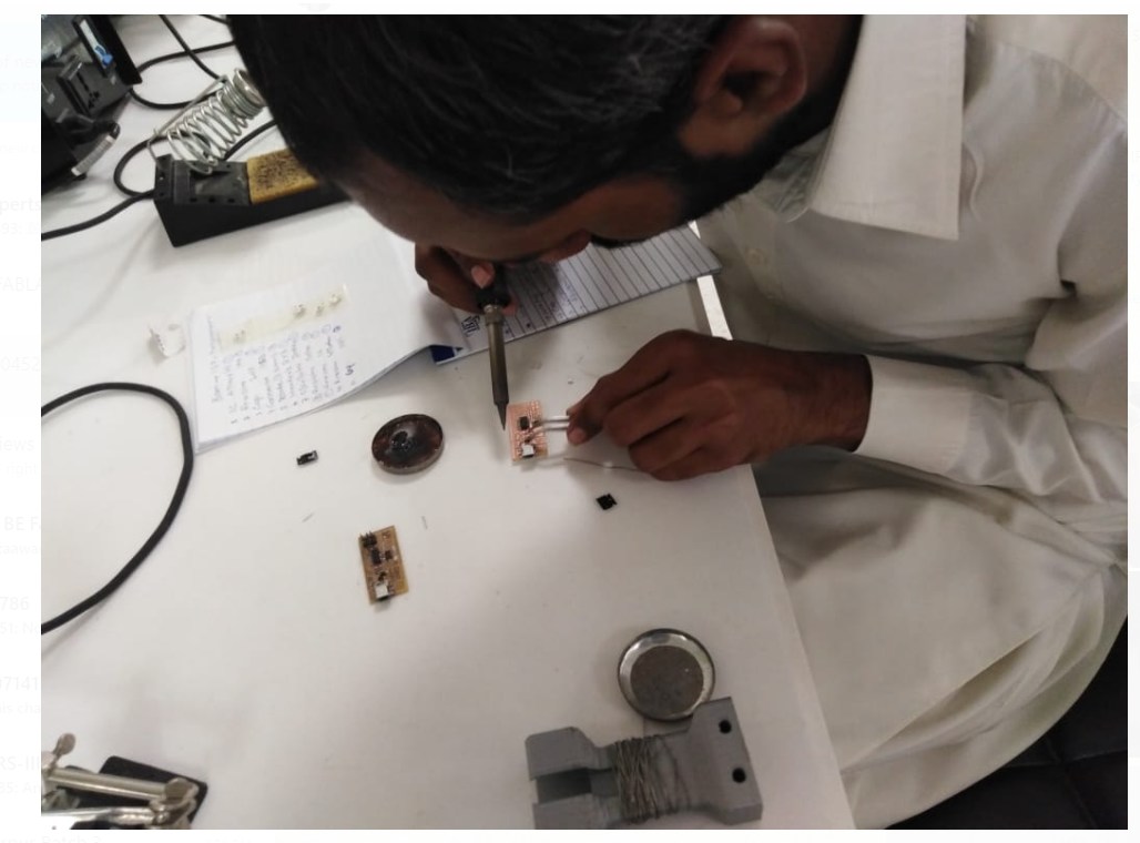
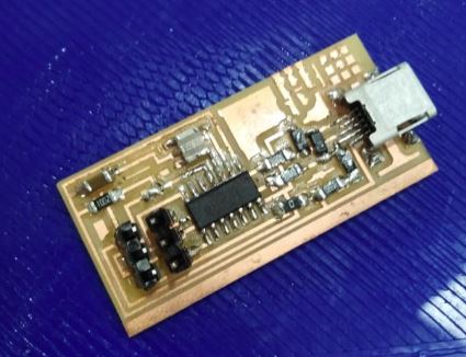
After the Soldering ISP Programmer ATTINY-44
Programming to ISP
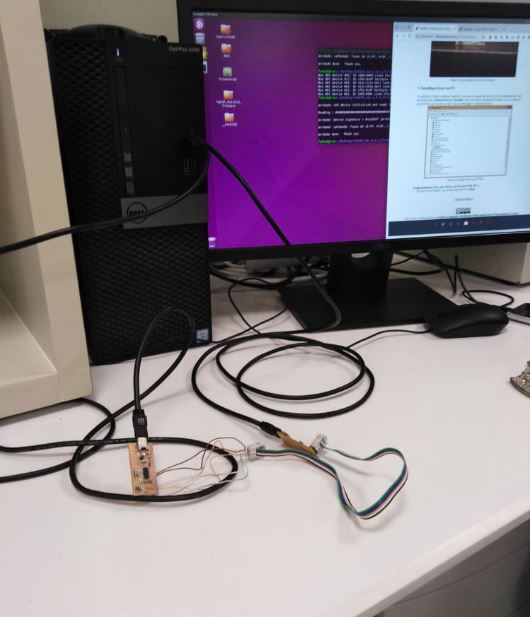
for the ISP Programing, I am using Ubuntu OS Operating system based computer to program my fab ISP in Ubuntu. Here Procedure is defined, So the part is programming, for programming ISP circuit, so lab has issue on PC that is already installed Ubuntu operating system and I have Followed these Instructions.
For programming ISP using Ubuntu a brief step-by-step process is explained HERE
the Software’s and drivers necessary can be downloaded from below mentioned Links:
First Downlaod The FAB ISP Firmware
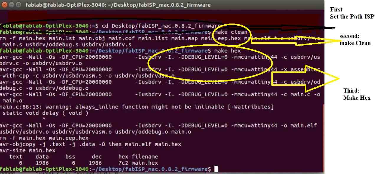
After completing above steps correctly, go to Terminal of Ubuntu and Type following commands:
USB ATTINY-44 Connections for the ISP Program:
Now These are the Intuctions for the ISP Progam that we have to fellow to up the ISP.
After the Downlaod and Add the File , Libararies so On and set the Path of ISP Firware :
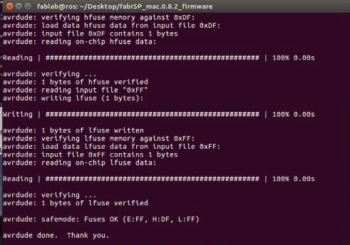
Now its time to Make fuse
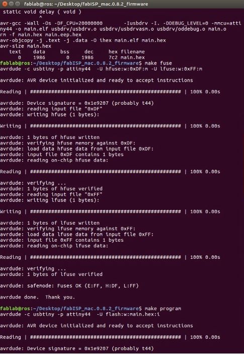
Now Make Program :
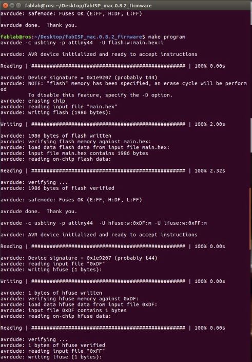
Now It Complete the Program in ISP ATTINY-44 Programer:
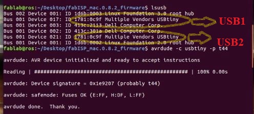
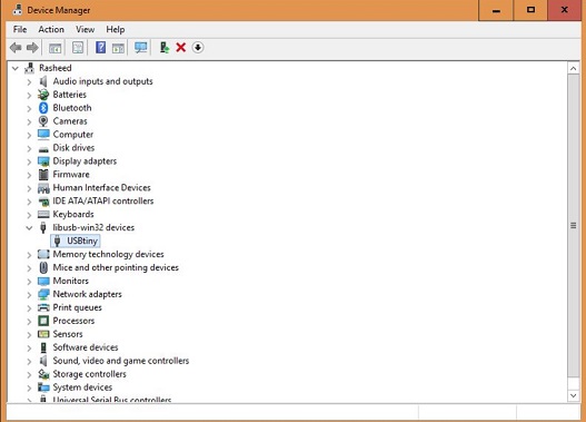
Now Use the Lsusb Command to show the Attiny Borad verifications:
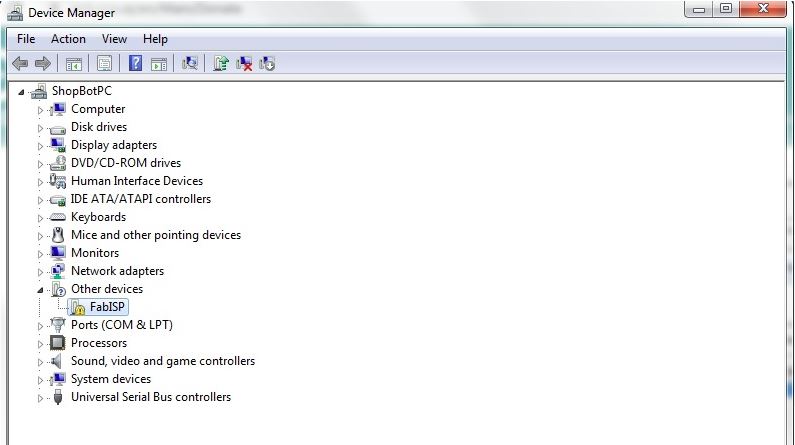
After This I have test My Design Board on the Window, So My design Board is working on the Window
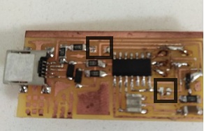
Removing Zero resistors (jumpers)
After Successful programming its turn to remove zero jumpers to make circuit as a programmer.
Further more Installing the drivers and test the ISP Programmer: .
So I need to install the drivers for the programmer. We can download from this site HERE
After the Installation the Drivers and Now My Design ISP Is working Successfully.
Results:
In this week we have design and Mill the PCB Boards, First, we have mill Assignments to check the machine and tool bits, in the first case we have faced some issues of Board Level and an old bit, so the assignments file after milling is not clear ,but in individual assignments, we have fixed all issues and mill it, my Assignments after mill is more clear and fine.
Conculsion
Being a Electonics Engineer , this Week was best week of perivous week yet, during the Diploma . I have enjoyed this week and learn lot of things for the PCB design,Trouble shooting and Manufacturing the Electronics Circuit .In this I have used the Eagle CAD design and for the Programing,Generate the RMl code,I have used the Ardiuno and C++ langauge as well as learned about the Embedded system Design.
Download all files from here

This work is licensed under a Creative Commons Attribution-NonCommercial-ShareAlike 4.0 International License