
Assignment :
- Individual assignment: Model (raster, vector, 2D, 3D, render, animate, simulate,a possible final project,compress your images and videos, and post it on your class page.
Before I am going to Software Portion , first I will define about the Vector and Reaster in 2D and 3D Designs
2D design
A 2d design professional draws 2-dimensional, or flat, images used in mechanical drawings, electrical engineering projects, video games, animation, clothing construction and architecture.What makes 2D so powerful? Drawing, Graphic Design, Photography, Painting, Video, and many other art disciplines rely on a designer’s ability to use the concepts learned in this course in order to communicate. All the elements of 2D make up a visual language that helps artists to communicate creatively and effectively while utilizing a wide variety of materials. The concepts you will learn have practical applications that help you express yourself in unique, artistic ways. for more detaits HERE
Raster :
In computer graphics, a raster graphics or bitmap image is a dot matrix data structure that represents a generally rectangular grid of pixels (points of color), viewable via a monitor, paper, or other display medium. Raster images are stored in image files with varying formats. HERE
Raster Software:
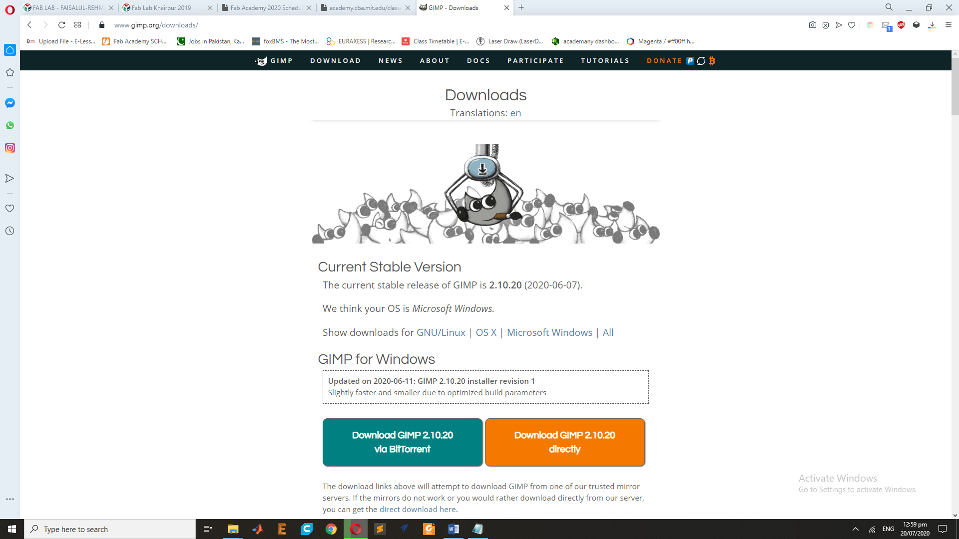
For the Raster Design I have choose to work on the GIMP Software , for the Raster process I used my picture to check the Raster results and Pixel.so first I have download the software from HERE and Install in My Computer.
After the Complete Installing Process ,Double Click on the GIMP Icon for Open the Software.
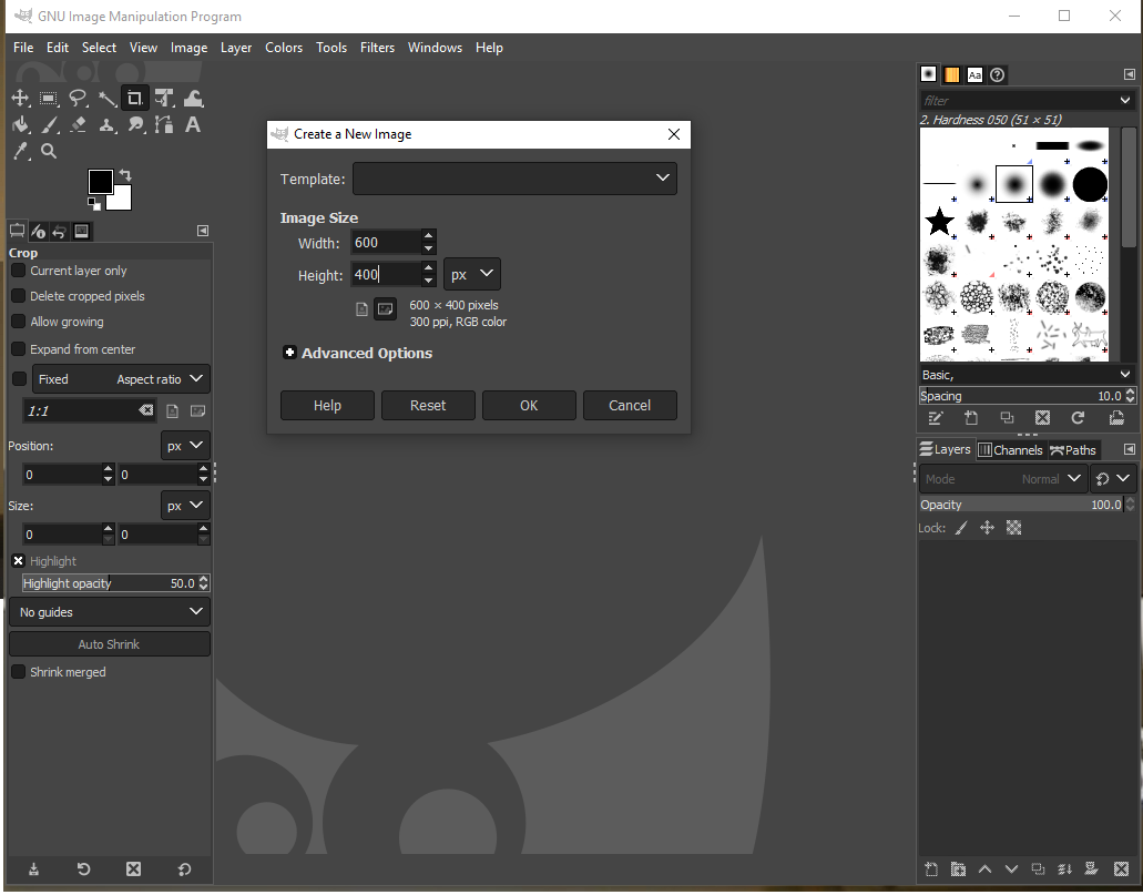
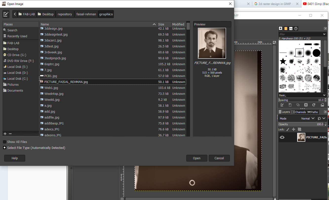
Now Goes to file and open the new file and set the Size of Image dimensions.
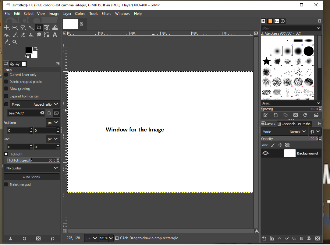
After the setting of the Image size and click to OK button this Window you will find.
Now goes to file and Import the Image for the Raster Process, So for this Process I choose to Work on my Image.
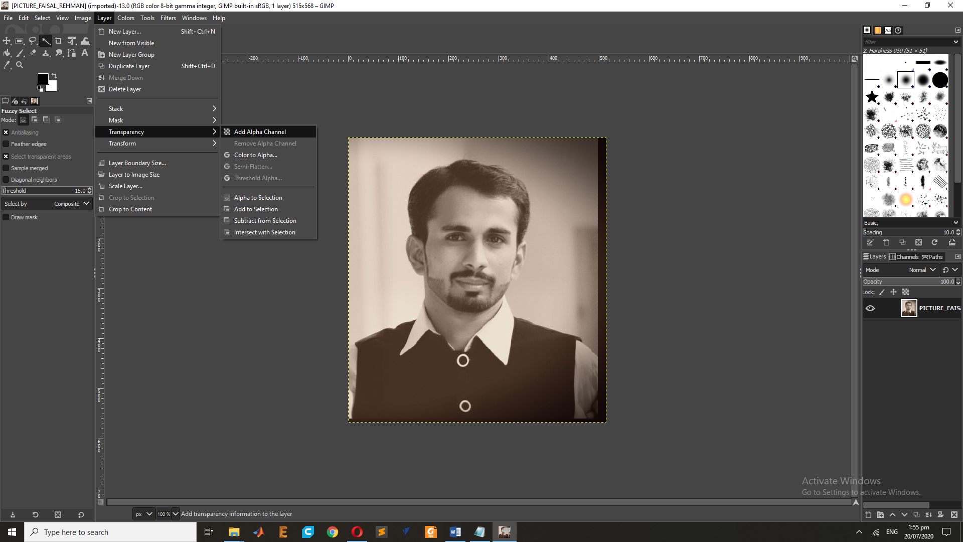
Now select the Fuzzy Tool and go to layer and Choose the Transpernacy " Add Alpha Channel" , and use the shafit Key and right click of mouse to set the Fuzzy boundery of the images.
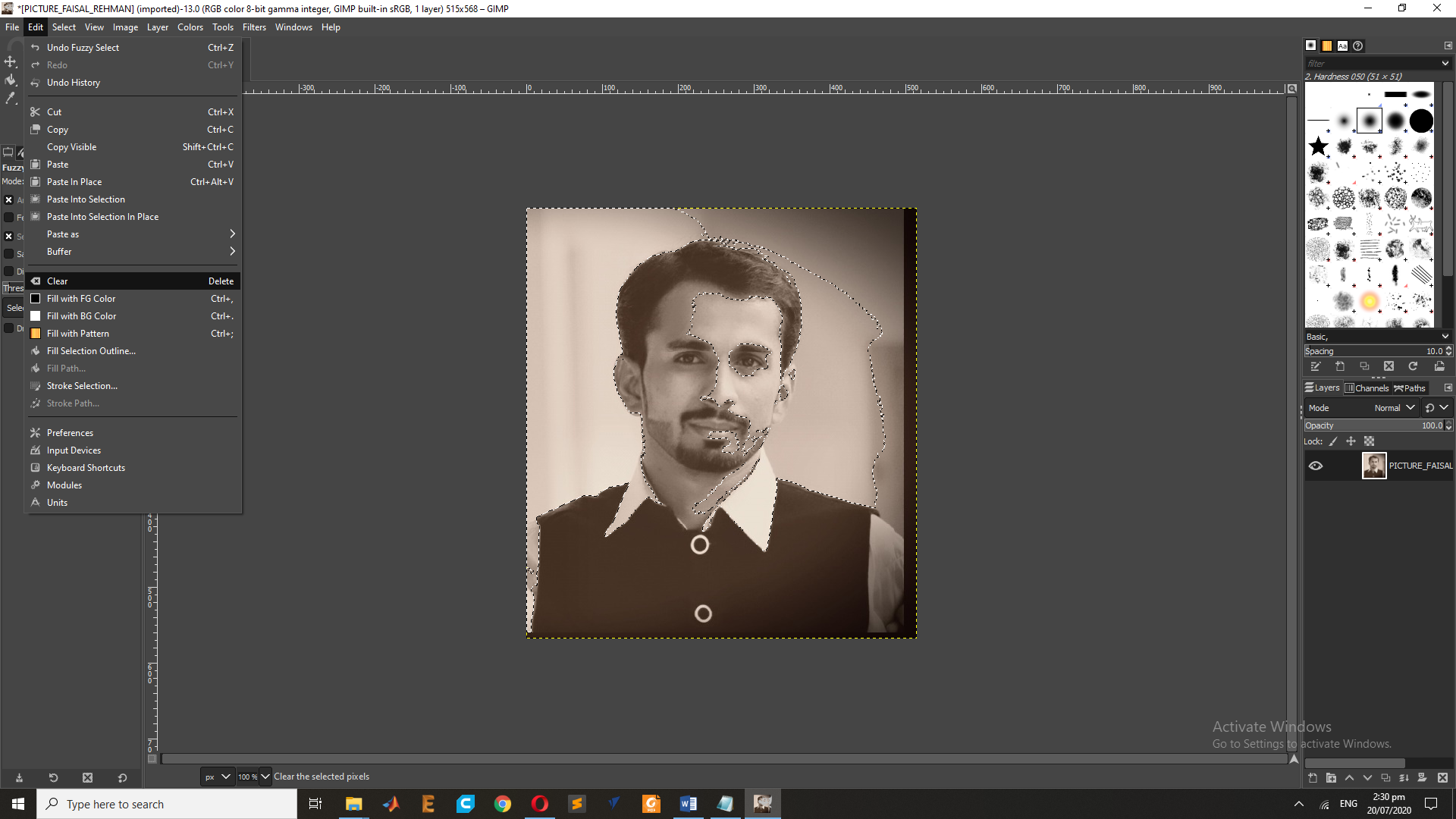
After this Process goes to eidt and clear it.
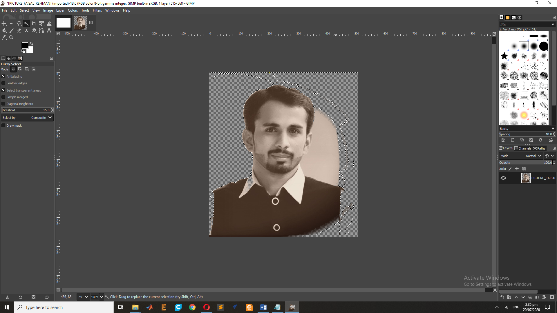
This the Final Result of the Image after the Transpernacy Process.
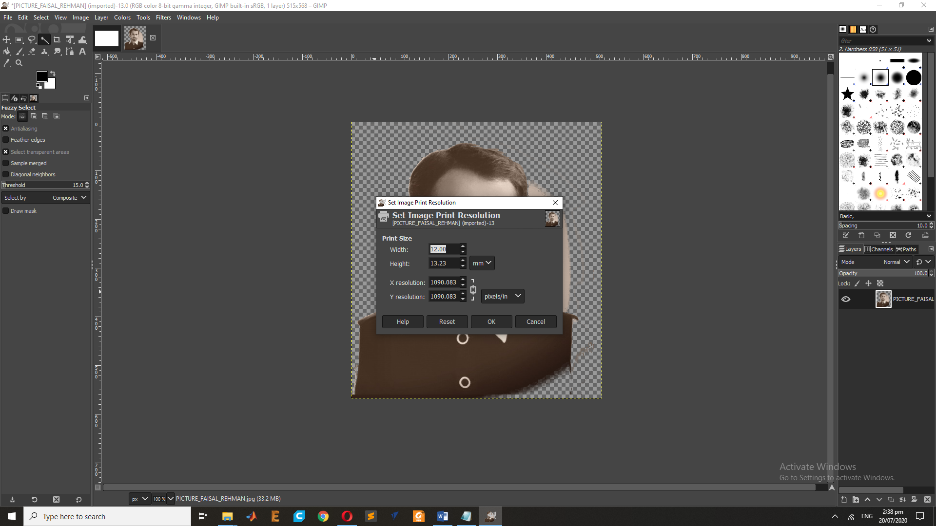
Now set the Print Pixel size of the Image in X and Y.
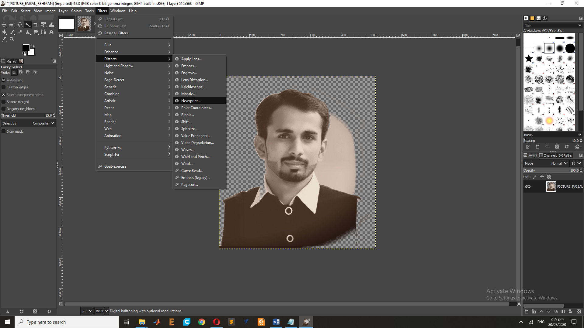
Now Goes to Filter and Select the "Distort" and Goes to "NewsPrint" for the Raster Result.
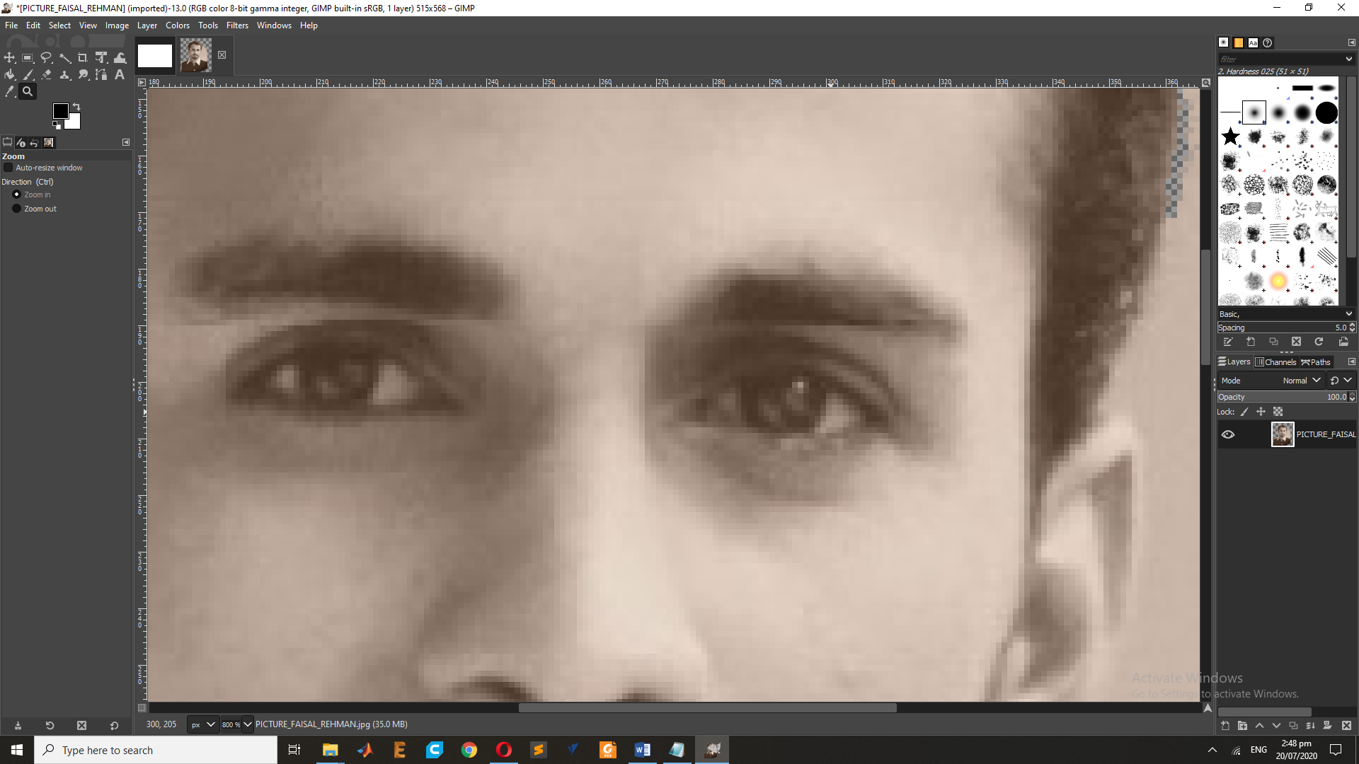
This is the Result of the Raster in RGB.
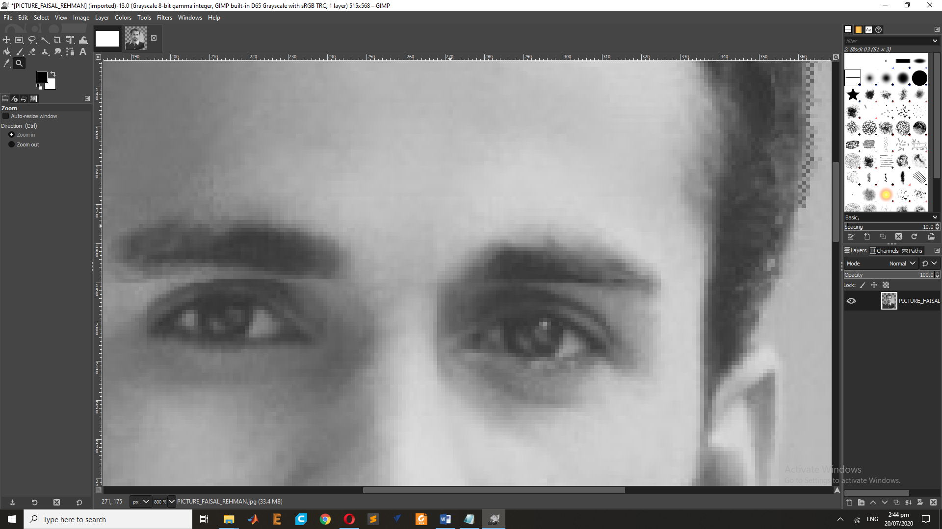
In Addisation I have use same process on the Gray scall image.so First go to Mode and and Select the Mode "Gray".
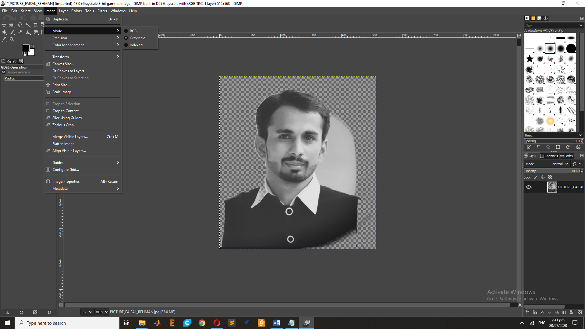
This is the Result on the GrayScall Image.
Vector Graphics :
Making use of sequential commands or mathematical statements or programs which place lines or shapes in a 2-D or 3-D environment is referred to as Vector Graphics. Vector graphics are best for printing since it is composed of a series of mathematical curves. As a result vector graphics print crisply even when they are enlarged. In physics: A vector is something which has a magnitude and direction. In vector graphics, the file is created and saved as a sequence of vector statements. Rather than having a bit in the file for each bit of line drawing we use commands which describe series of points to be connected. AS a result a much smaller file is obtained.
Softwares of the Vectorized Graphics :
Vector Graphics In Inkspace :
for this task I have select The Inkscape it is a very simple tool that can be used for the 2D design, lets start some activity ,Inkscape can render primitive vector shapes (e.g. rectangles, ellipses, polygons, arcs, spirals, stars and 3D boxes) and text. These objects may be filled with solid colors, patterns, radial or linear color gradients and their borders may be stroked, both with adjustable transparency. Embedding and optional tracing of raster graphics is also supported, enabling the editor to create vector graphics from photos and other raster sources. Created shapes can be further manipulated with transformations, such as moving, rotating, scaling and skewing.
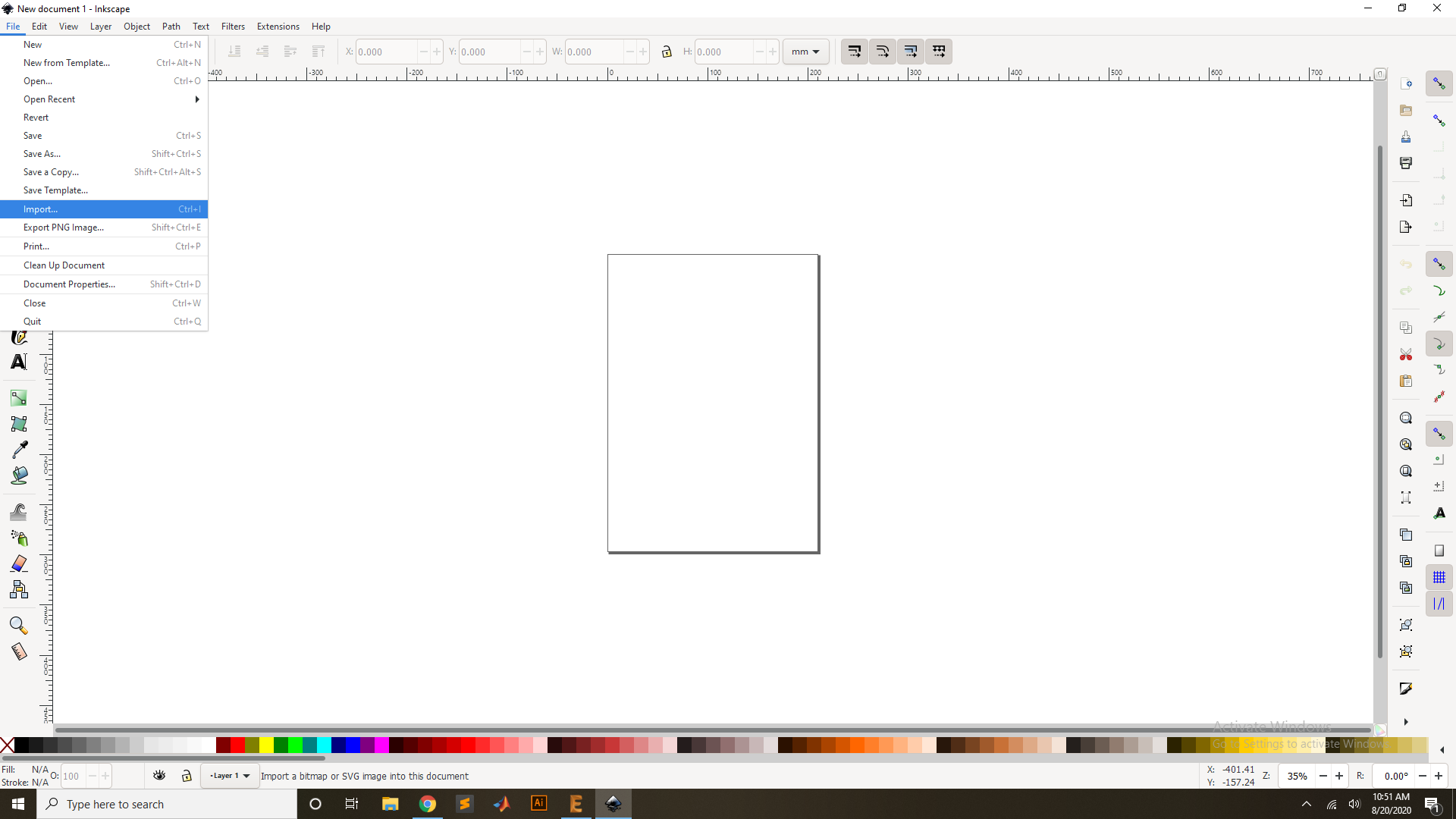
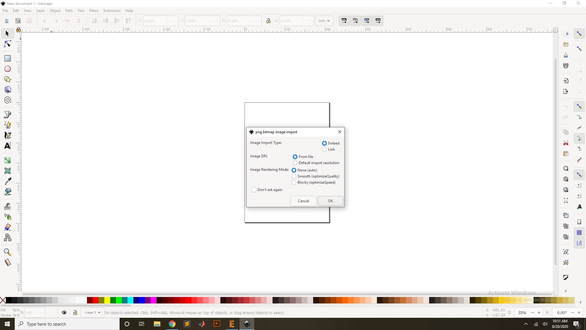
for the Vectorized I have download the image from the Google IMAGE , And Import on the Insakspace , For import the image by use the path function ==> Trace Bitmaps . At the time of vectorization you can draw the vector through three functions: brightness, border and color. and its Depending on the treshold you can set for the more clearances vector.
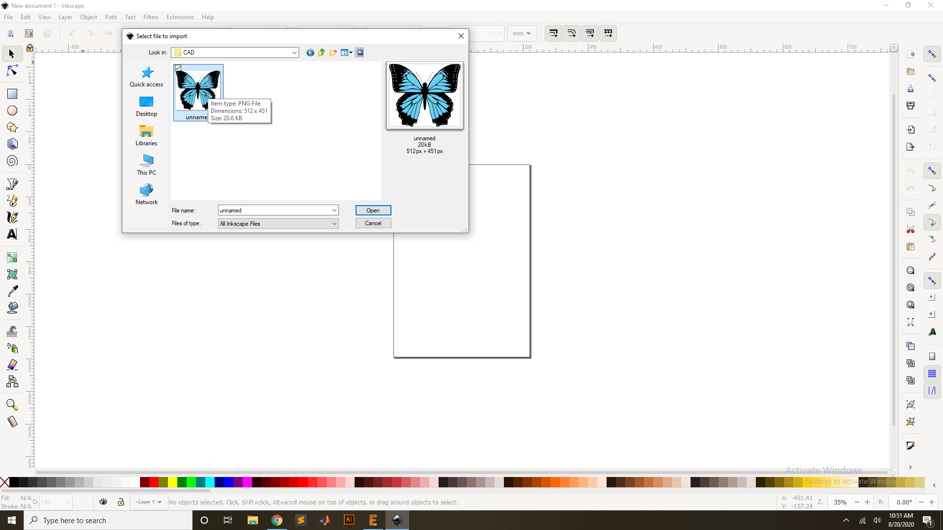
Now Import the Image for Porces
Select the iamge for the Vectorized and Open it.
then Press the ok for the Process.
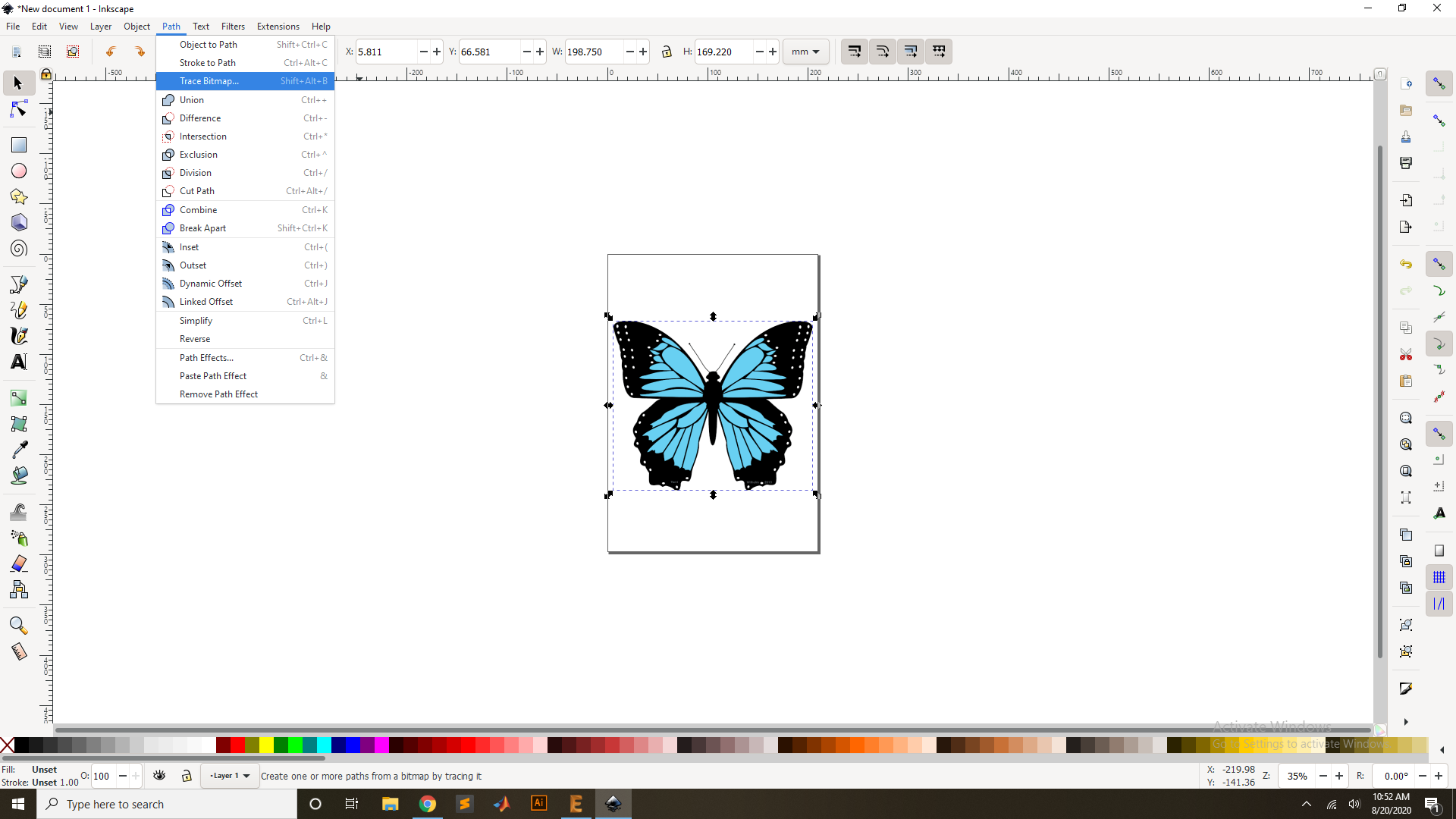
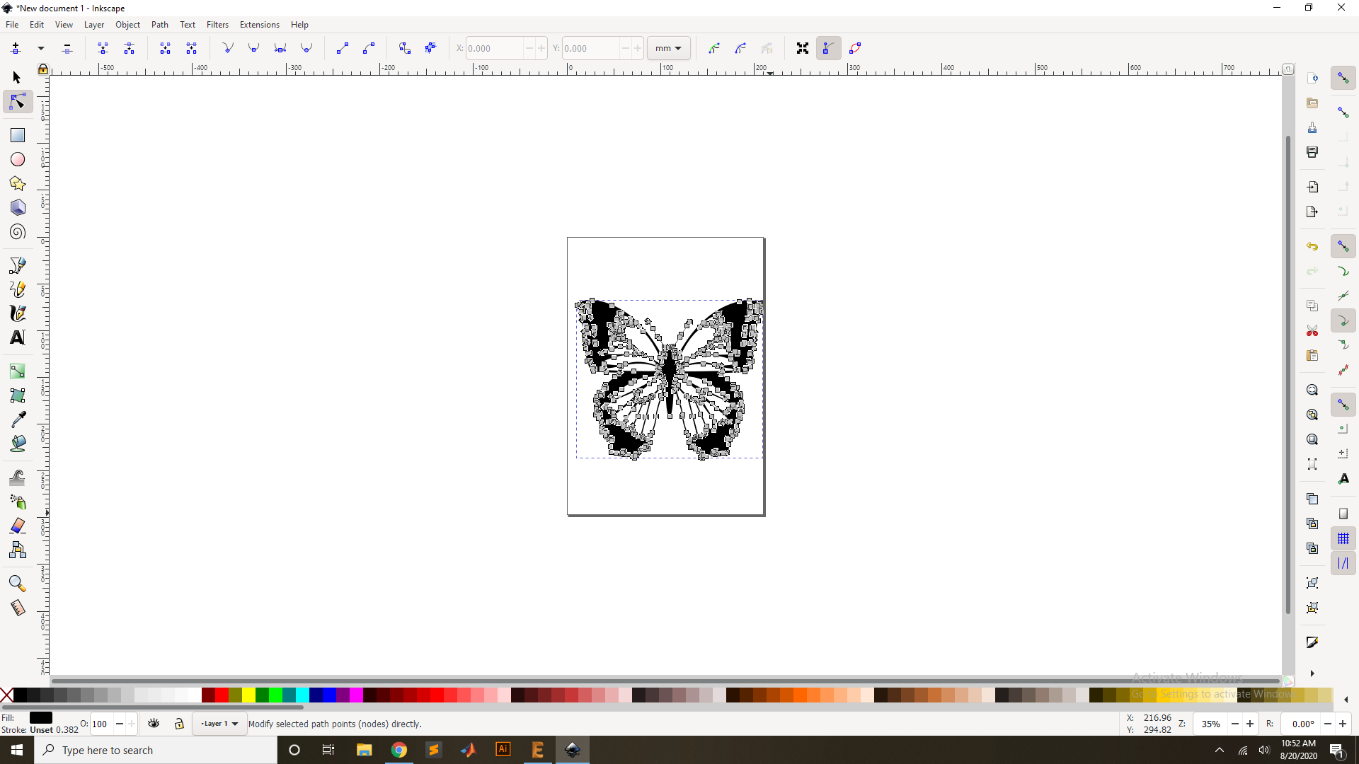
Now go to the path and Select for the Bitmap trace or Press "CTR+Shift+J".
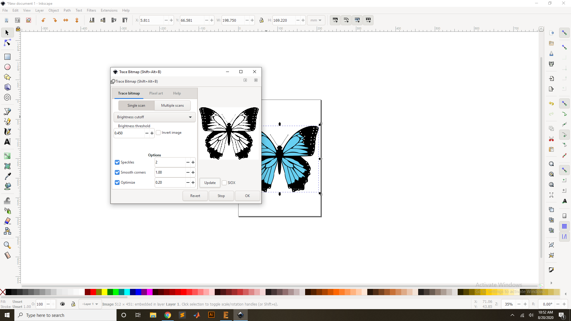
Now press the "Update"Key for the vectorized.
Now Press ok and then remove the Origional Image.
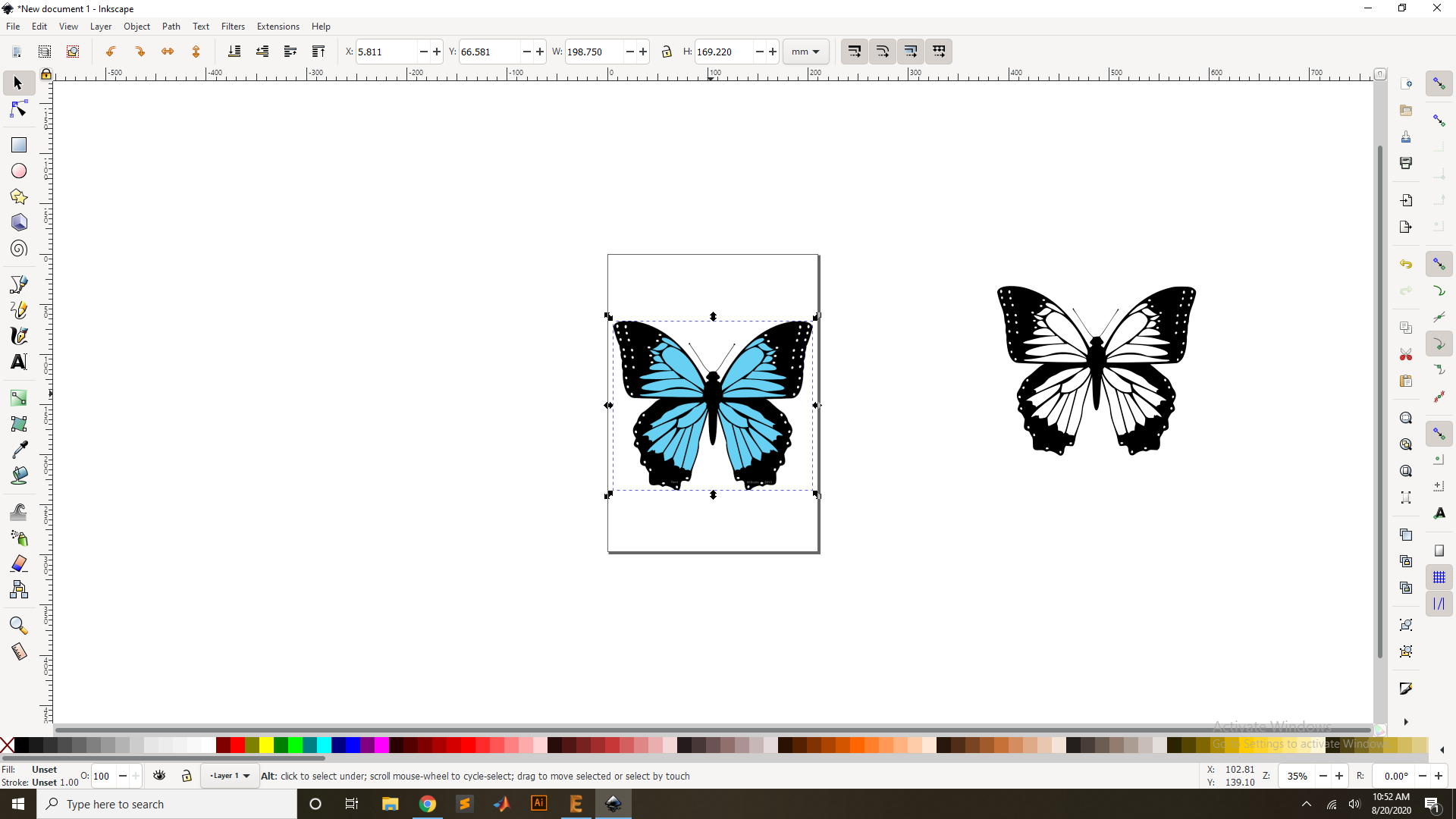
Now set the Origion of the Image and see the Vectorized
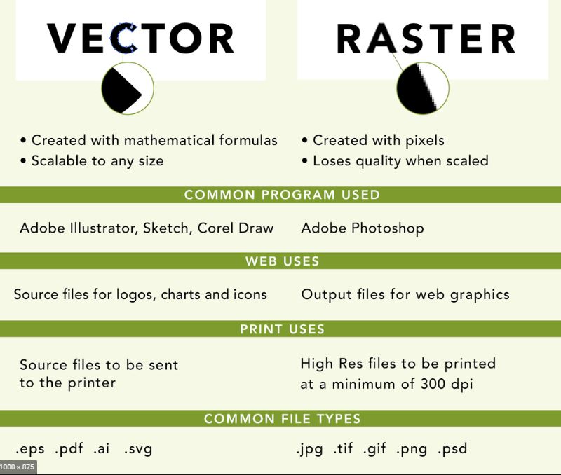
Raster VS Vectors
3D design in Solid Work
3D modeling is the creation of a three-dimensional object inside of simulated software. The object can be created from simple shapes all the way up to complex high-polygon models. A polygon is one triangle, and It takes many triangles to make a circle or complex object.
Parametric Design
Parametric is a term used to describe a dimension’s ability to change the shape of model geometry as soon as the dimension value is modified.They could be a combination of sides and angles as taught in school geometry. A CAD software allow you to create a drawing of a triangle with parameter information and then allow that drawing to be automatically changed by changing the parameters is a parametric software. Here.
Non Parametric Design
A non-parametric model does not contain such relationships. It is essentially a "dumb model" which often happens when a CAD model is imported from another program. Dumb models can be modified, but they do not have the additional constraints and relationships to allow the update to affect other design elements. Here.
Softwares:
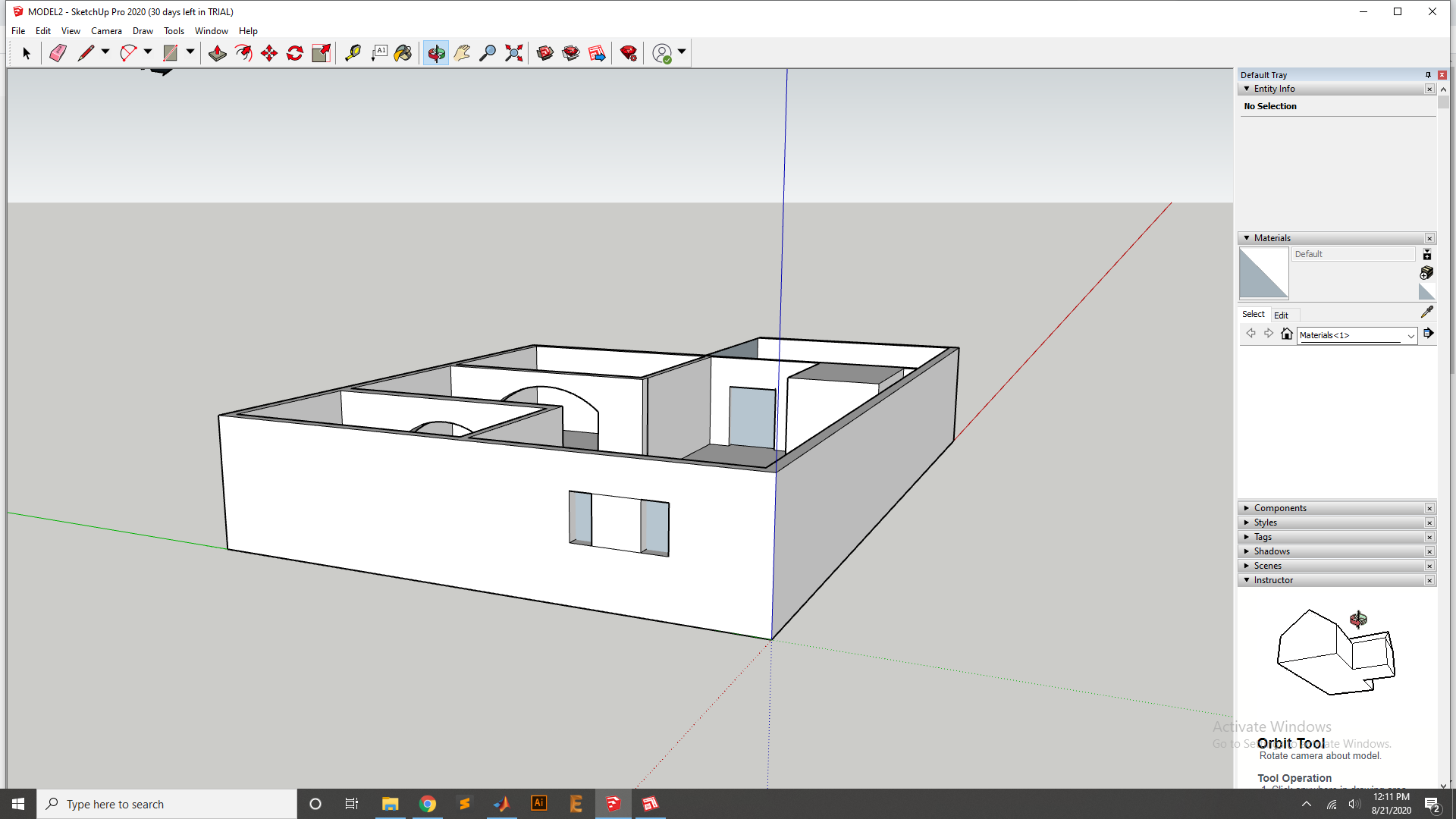
To design the None parametric design I have use the Sketup software so first I donwload it from Here. and install to my Computer and start to design the home Architecture with window wall and doors.
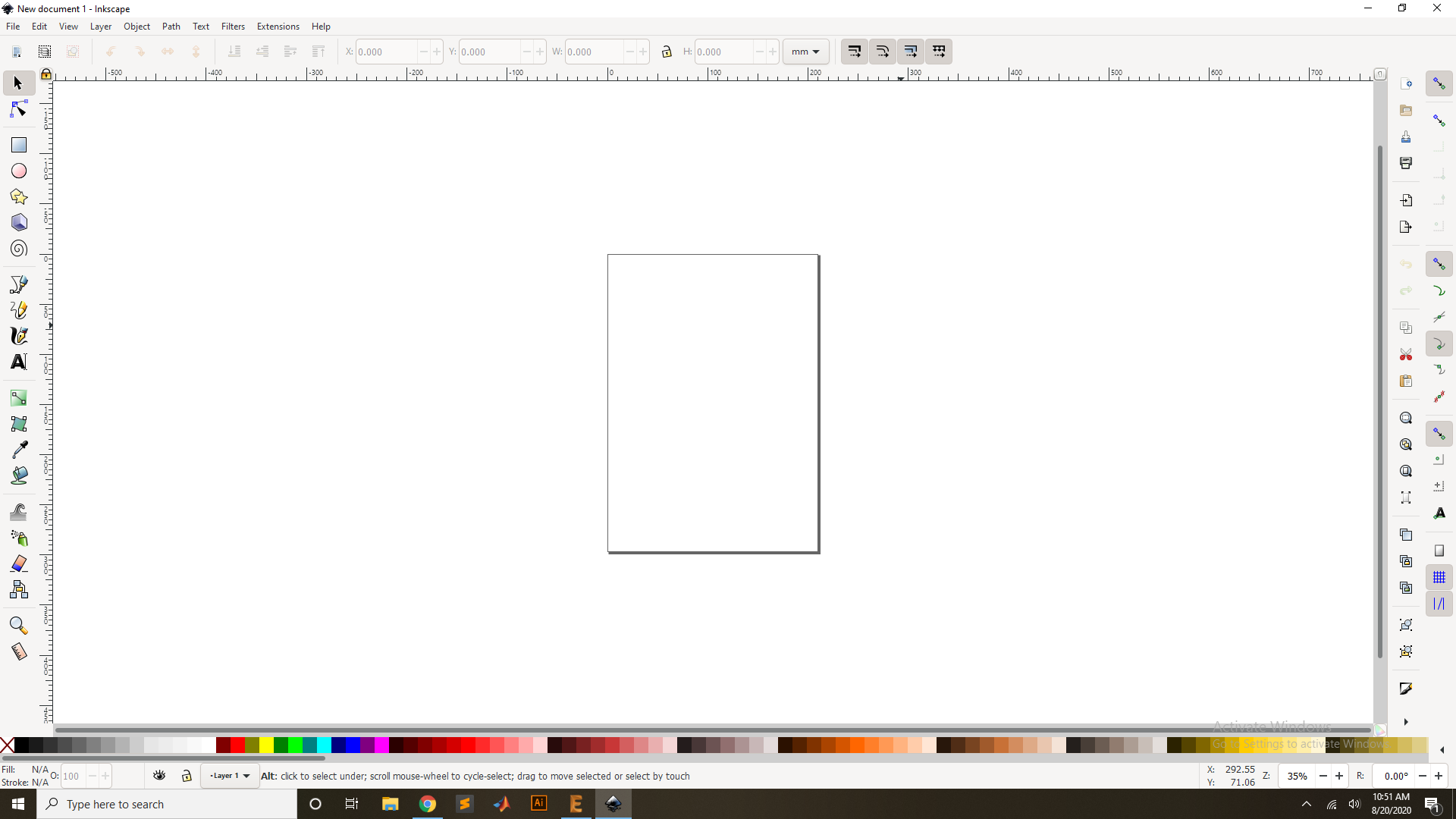
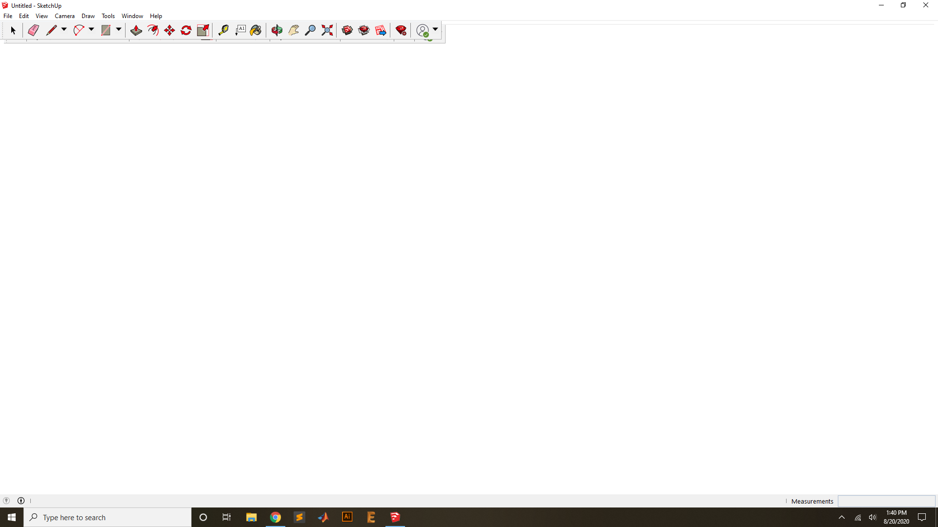
First open the Sketup software for the design,This is the Sketup software window where I have to design the Work.
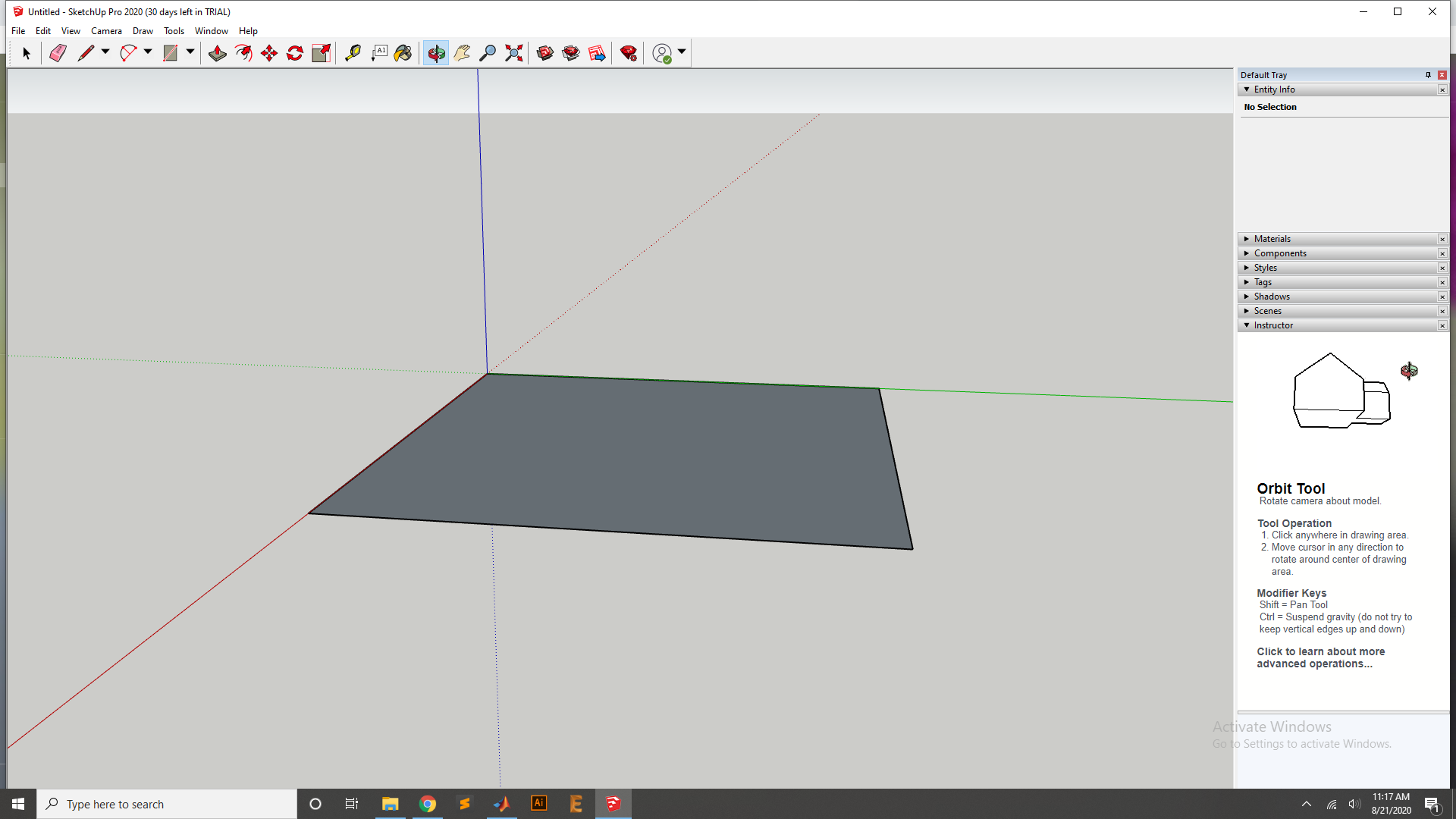
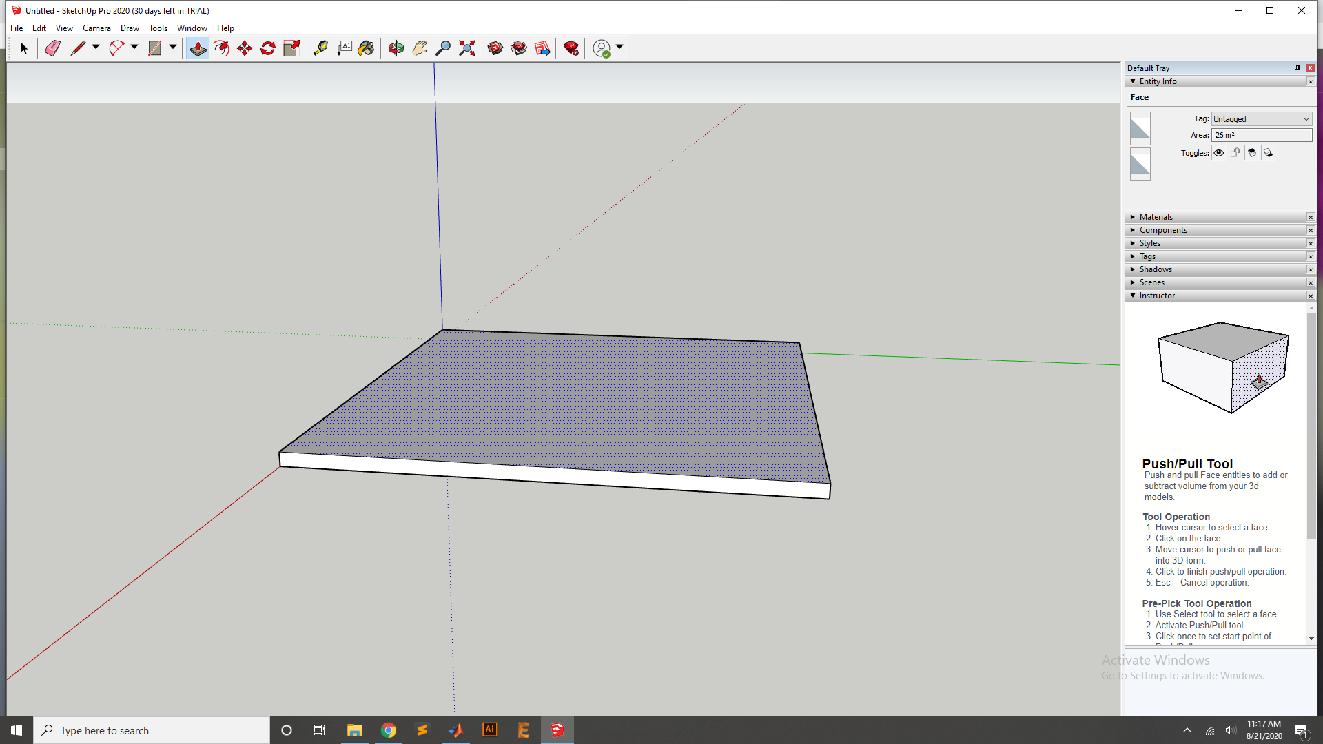
First draw the reactangle for the base of the Home.
Now Extrude the Base by Using the Extrude Tool.
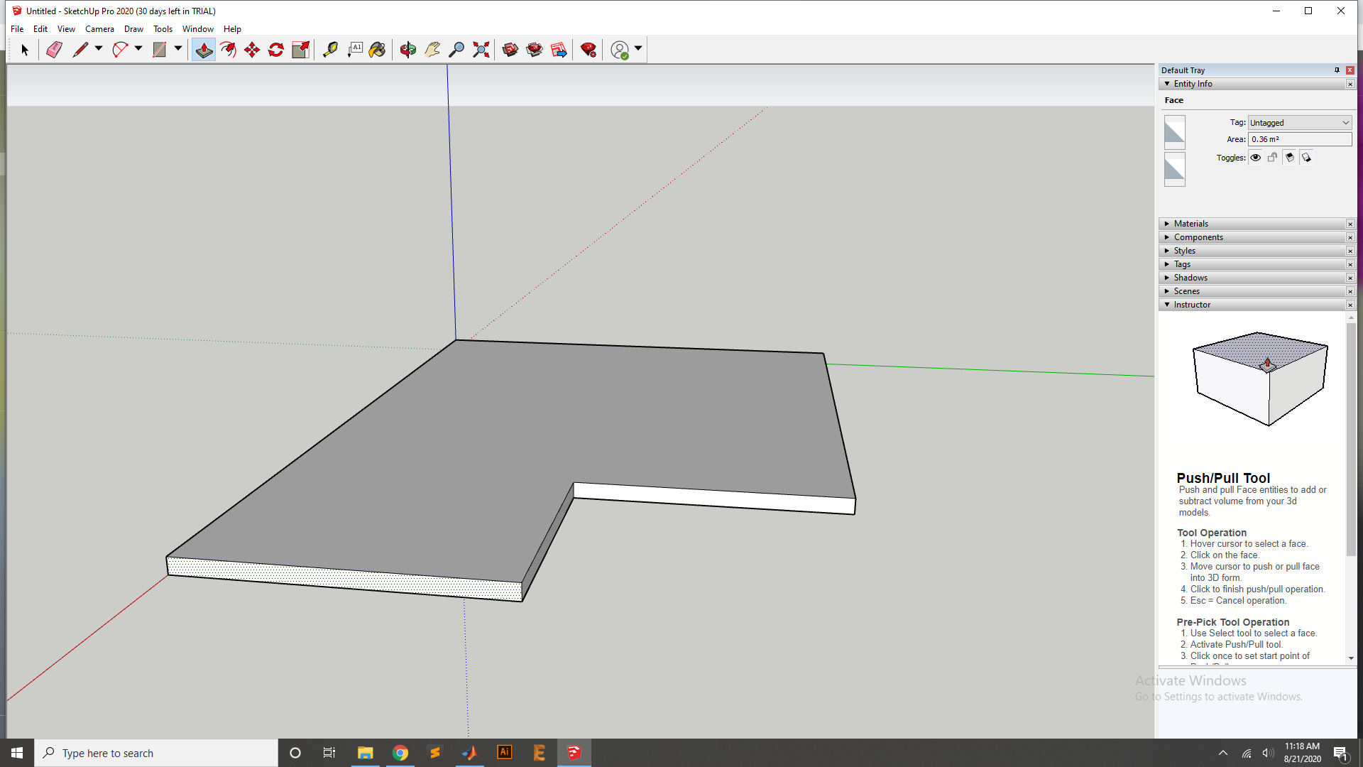
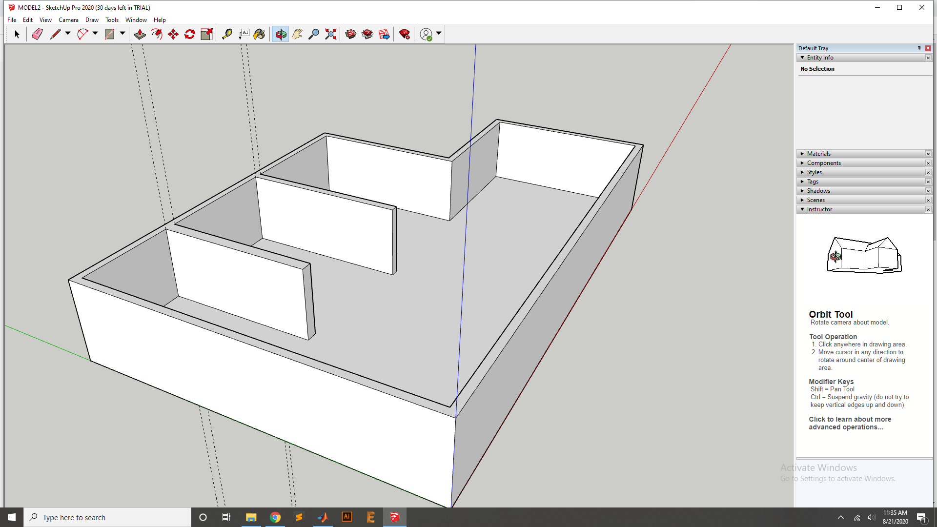
After that I have cut one side into part and extrude it with Extrude tool for the other room.
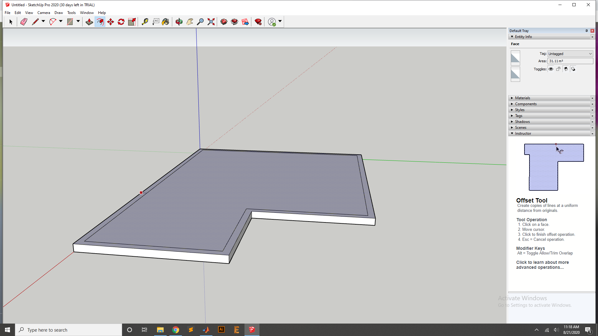
Now I have to design the wall for the Home so I have first aet the Boundary of the wall by using Offset tool.
Now Extrude the Wall of with Extrude Tool.
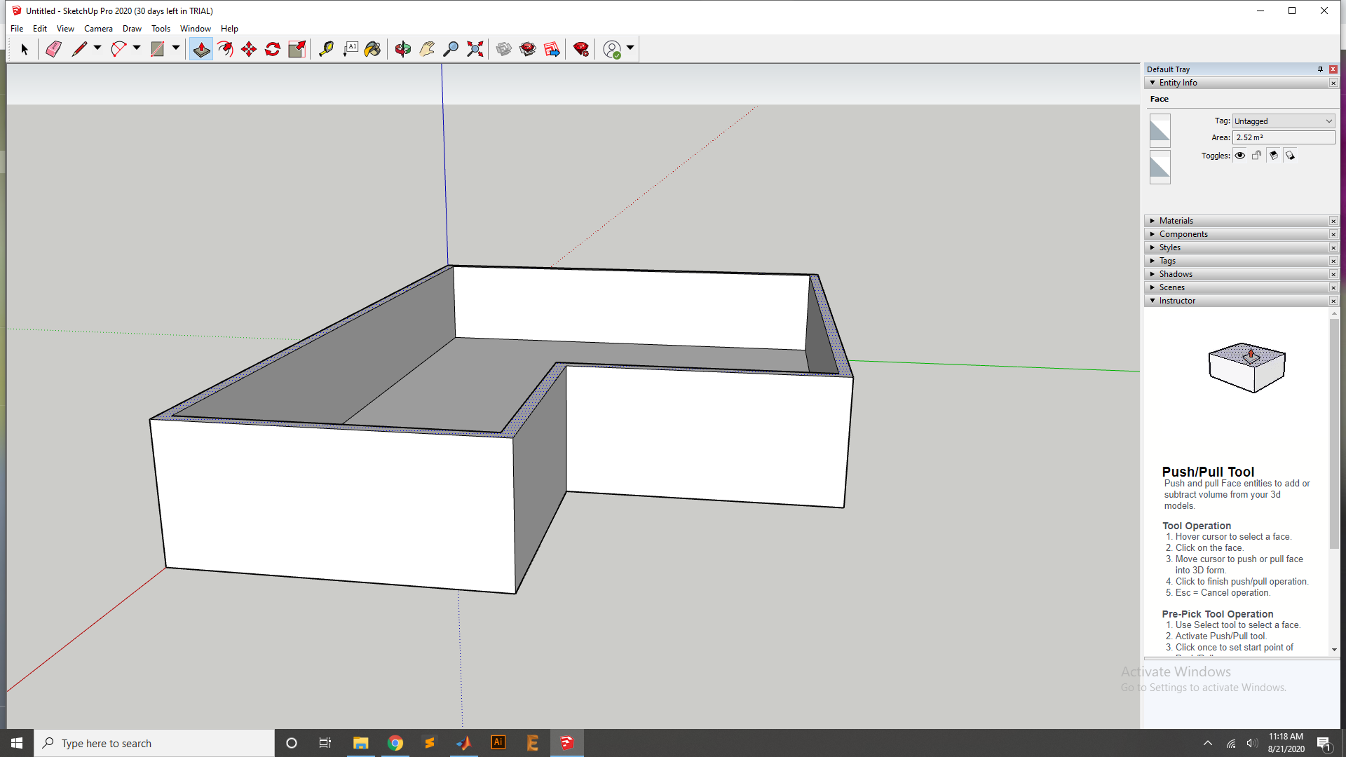
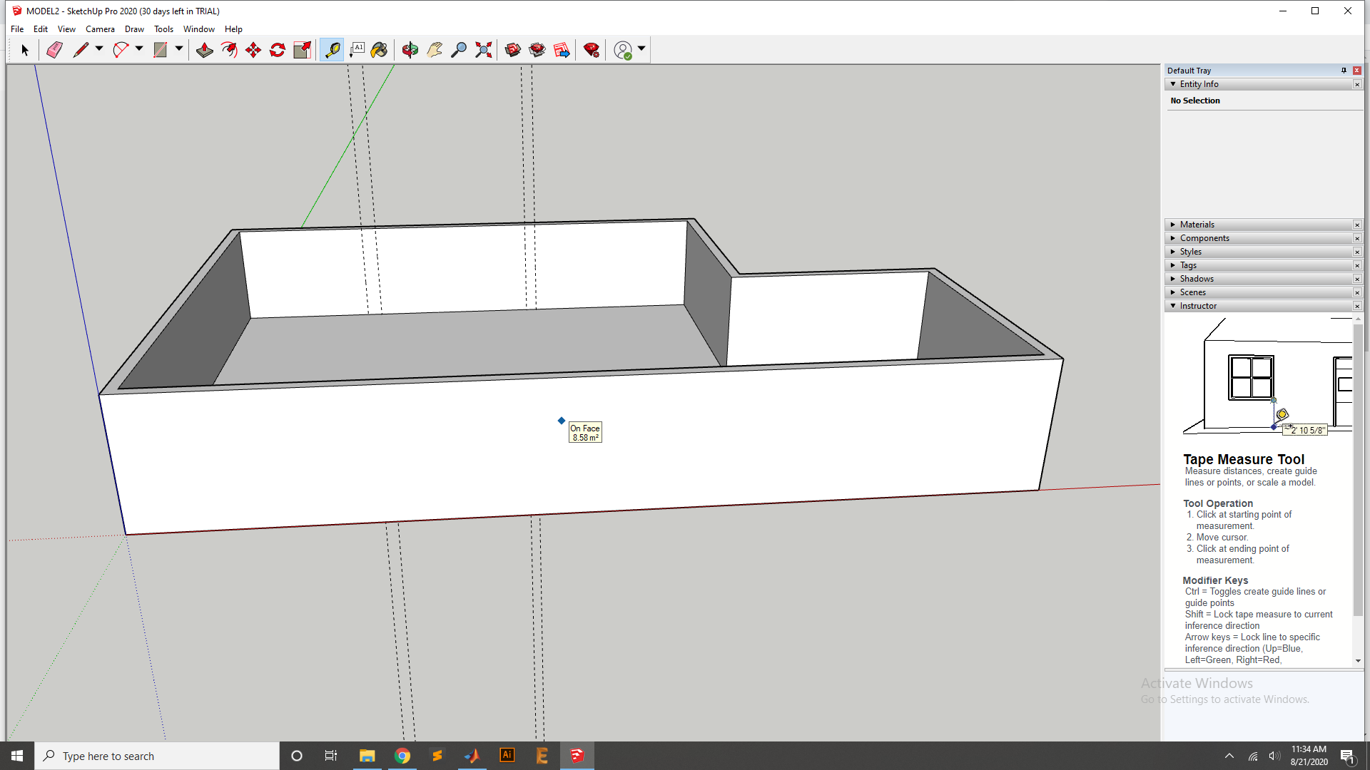
After Extrude now wall looks. and using Tape for design
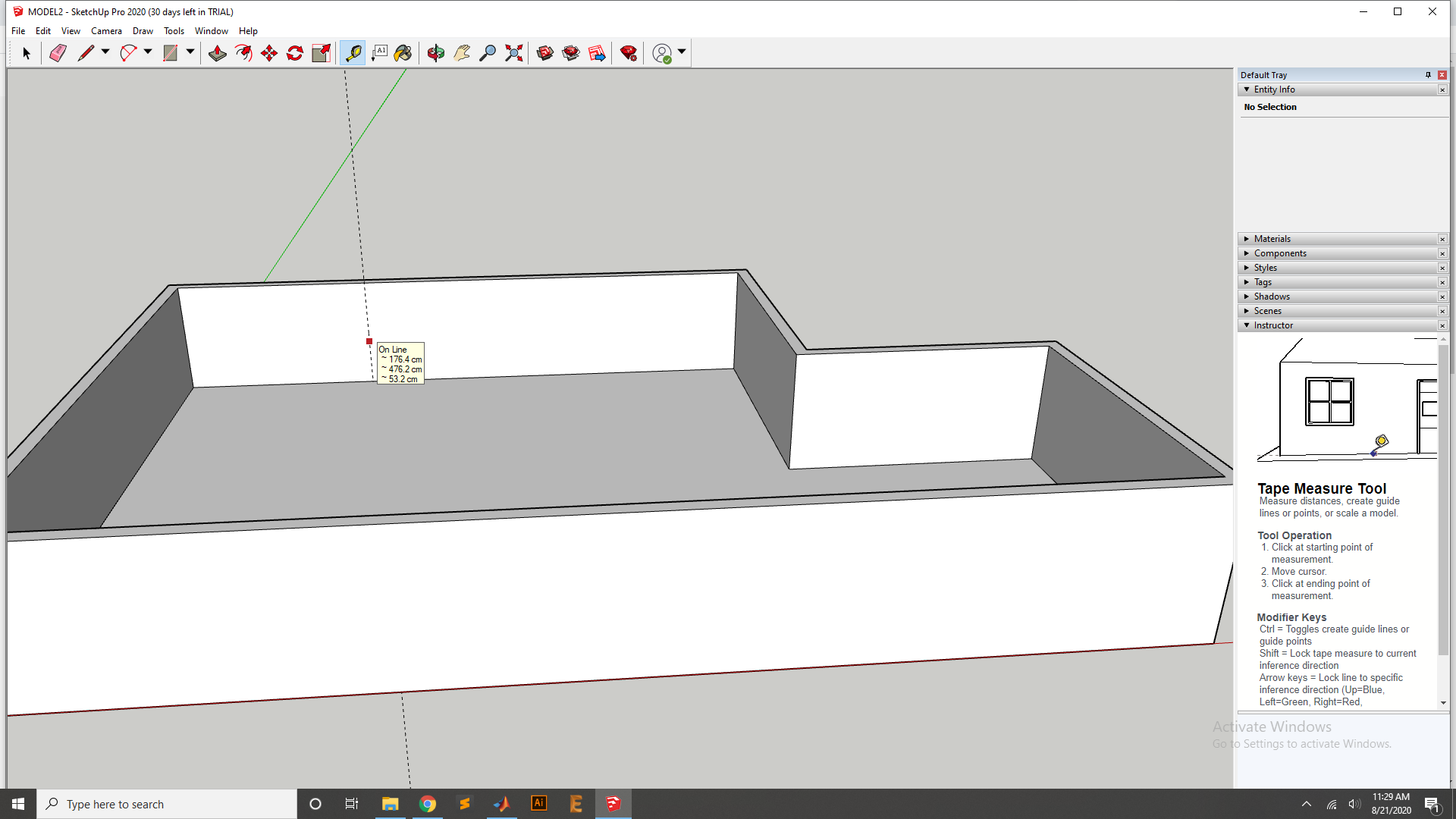
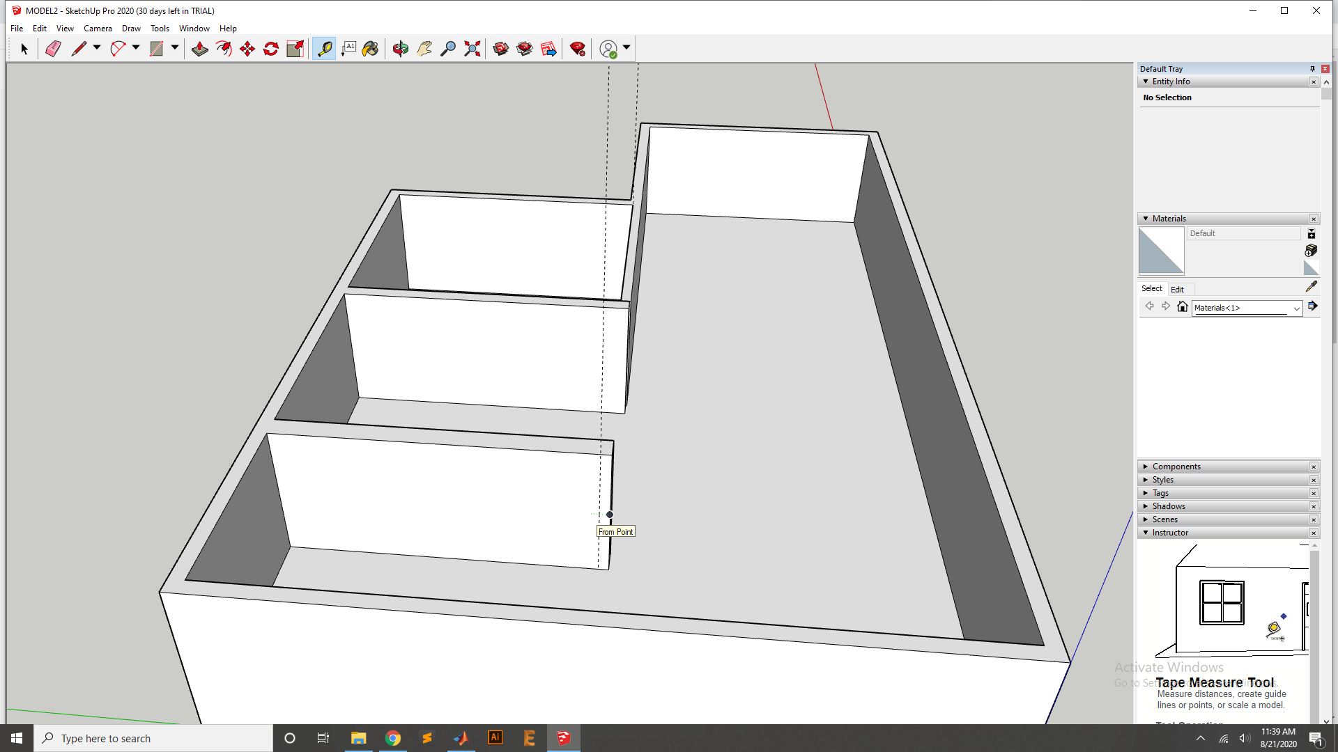
Now use the Tape Measure Tool for the inside wall and other Sides.
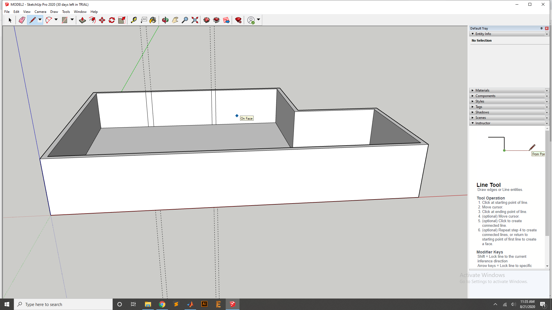
Now select the Line tool to fixed the measured the inside wall.
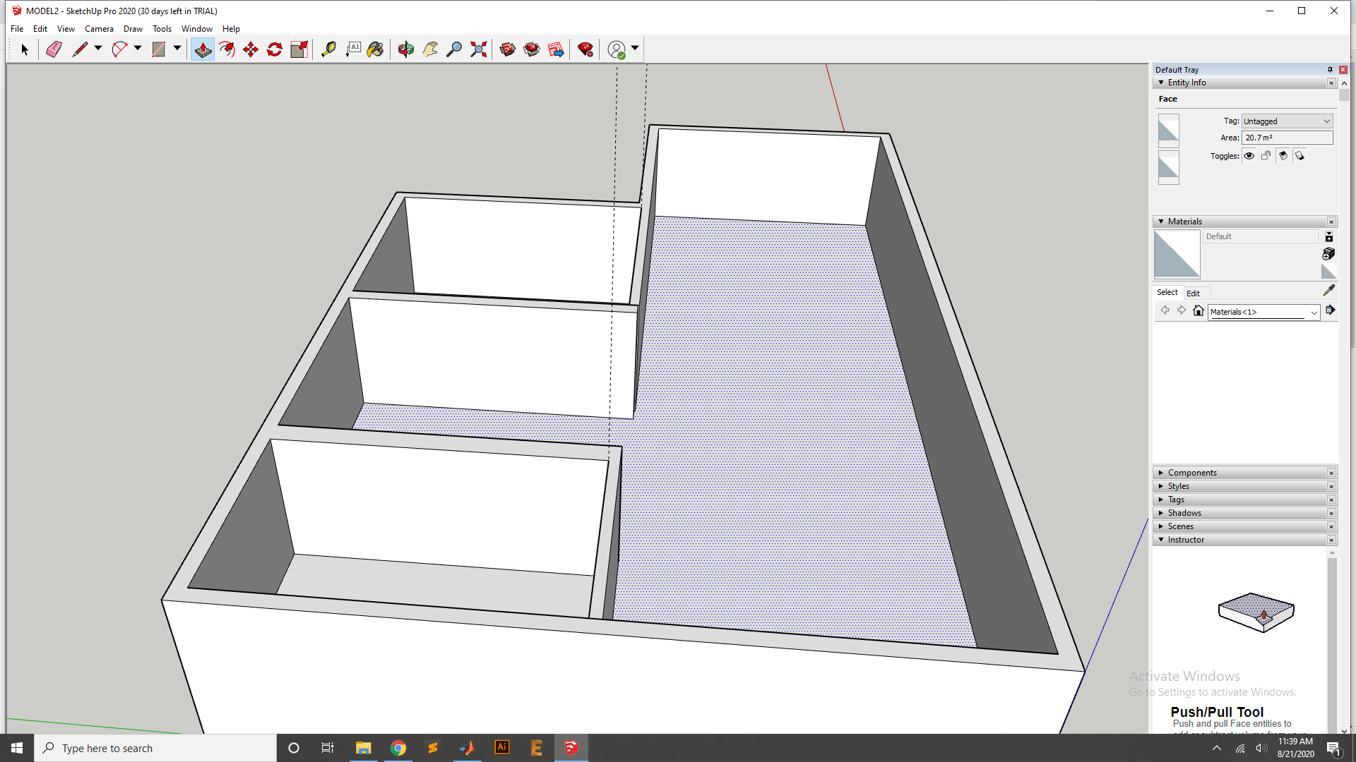
Now extrude the both iner wall using the Extrude tool.
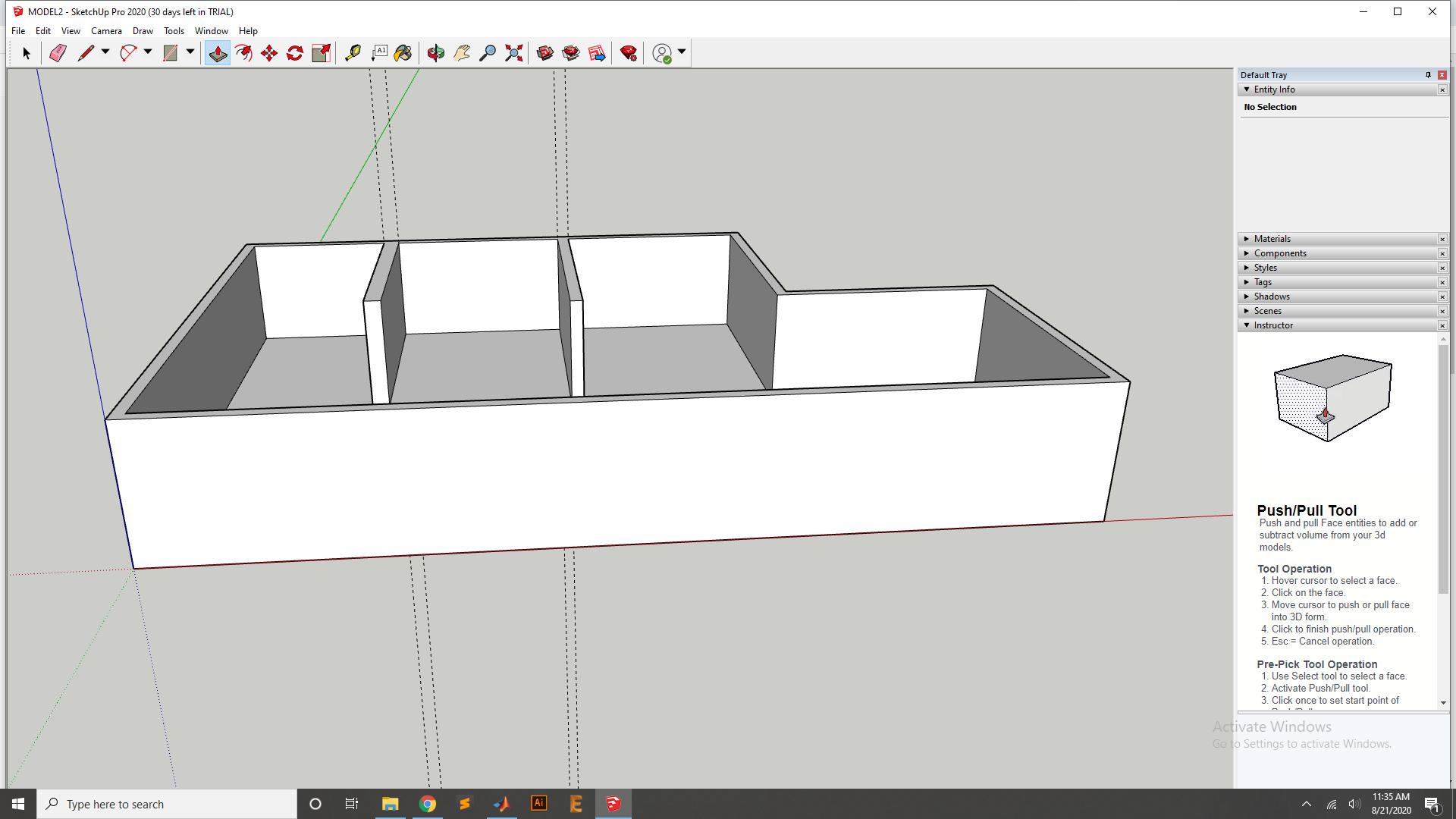
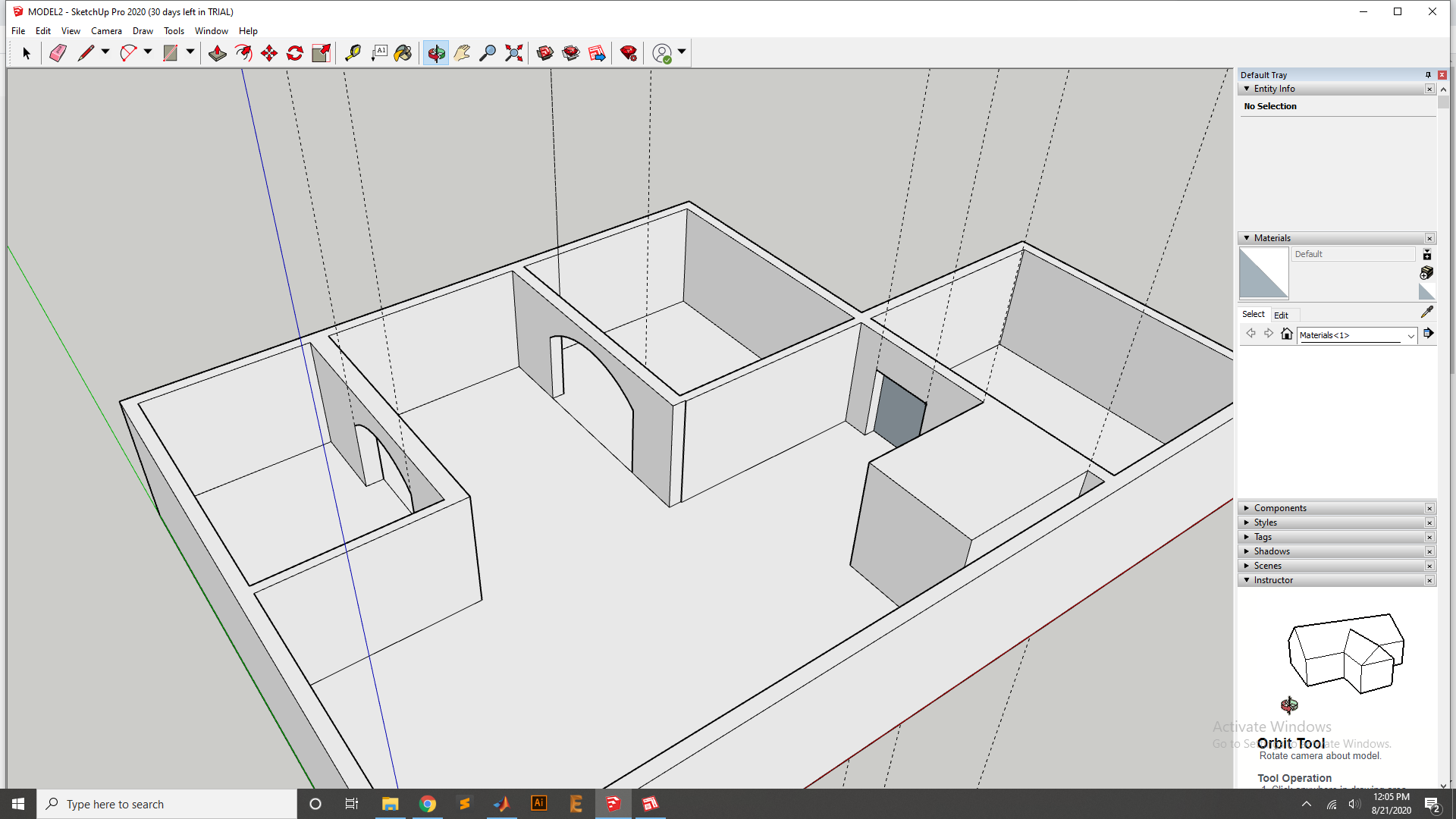
After the Extrude the wall.
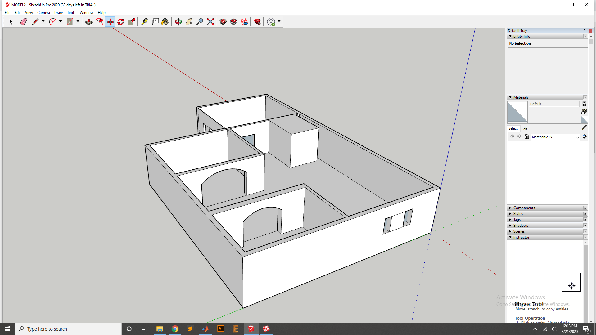
add an other wall and to complete the room
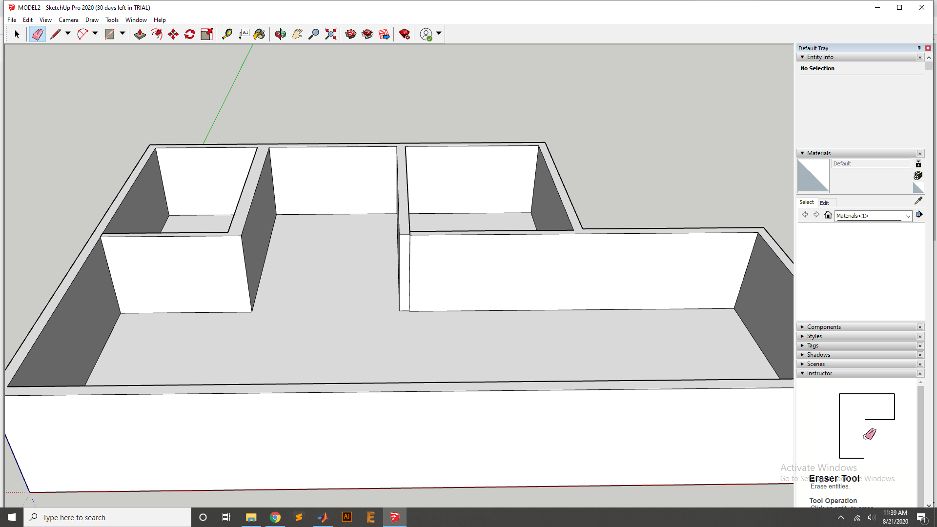
Now add wall an nother side of Design for the Room and then Extrude it.
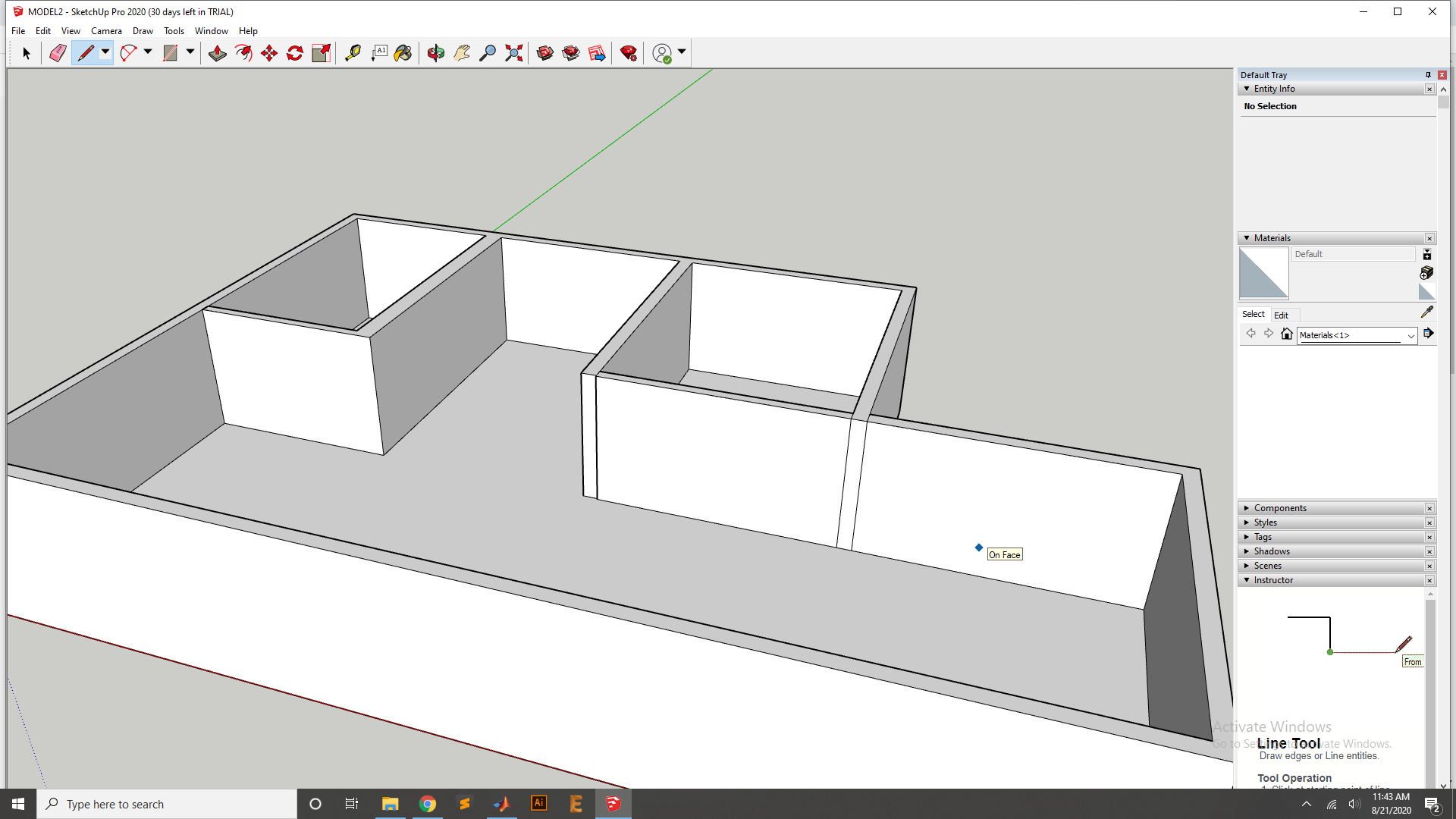
Now it look like that.
Now add one more wall for the other room.
Now extrude the Wall and fixed to other end.
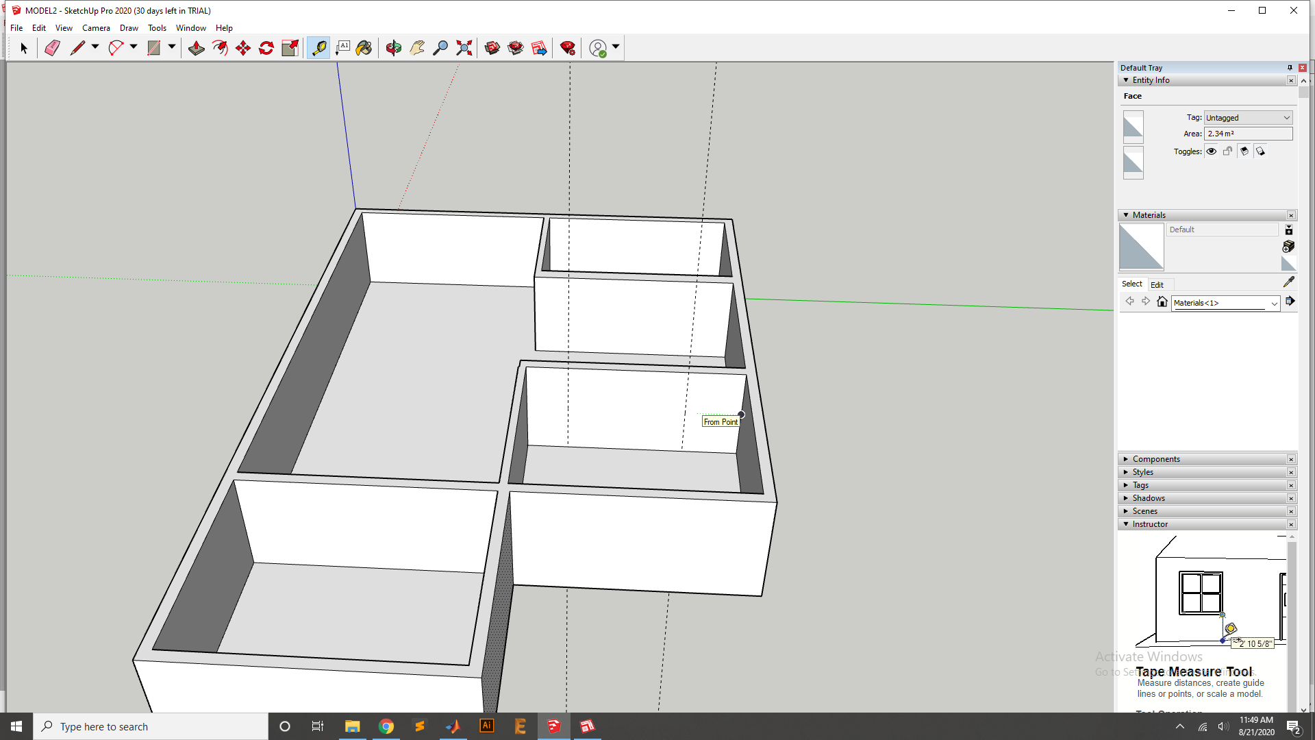
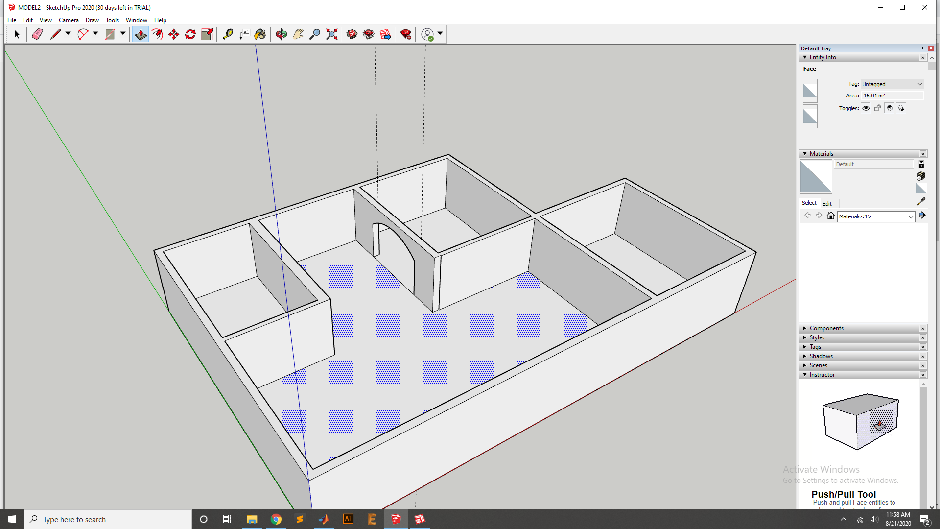
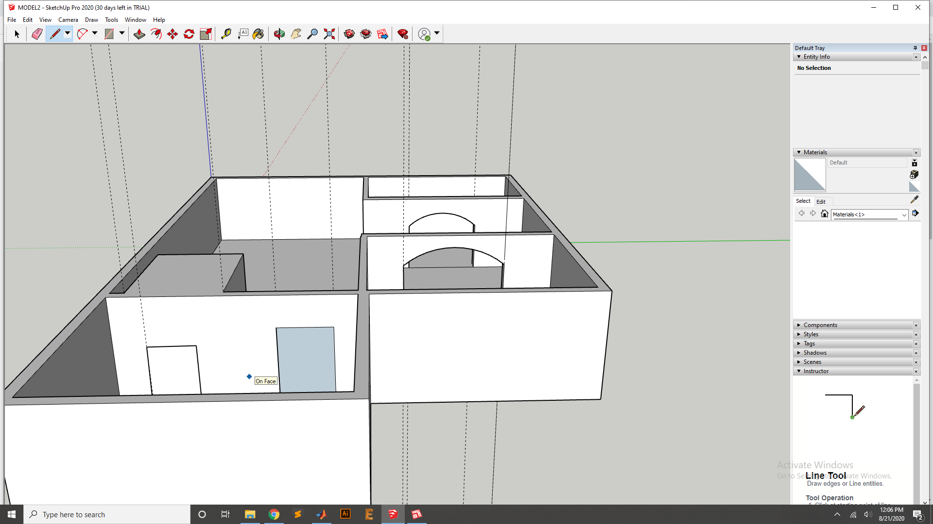
Now take the pen and draw the line for door.
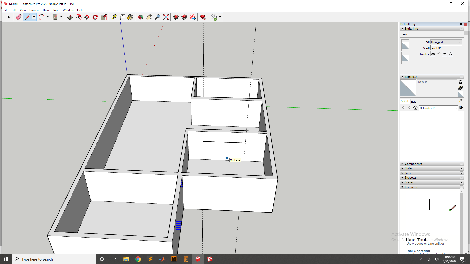
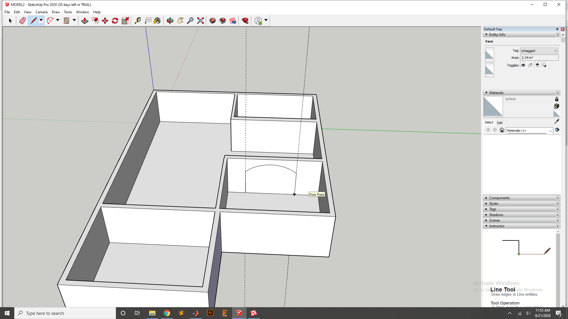
Add the cure line for the Door uper side curve.

Now use the pen to fix the Door line.
Now use the Extrude the Tool to Extrude the Door Cut.
Same process apply for the Other door and Extrude it.
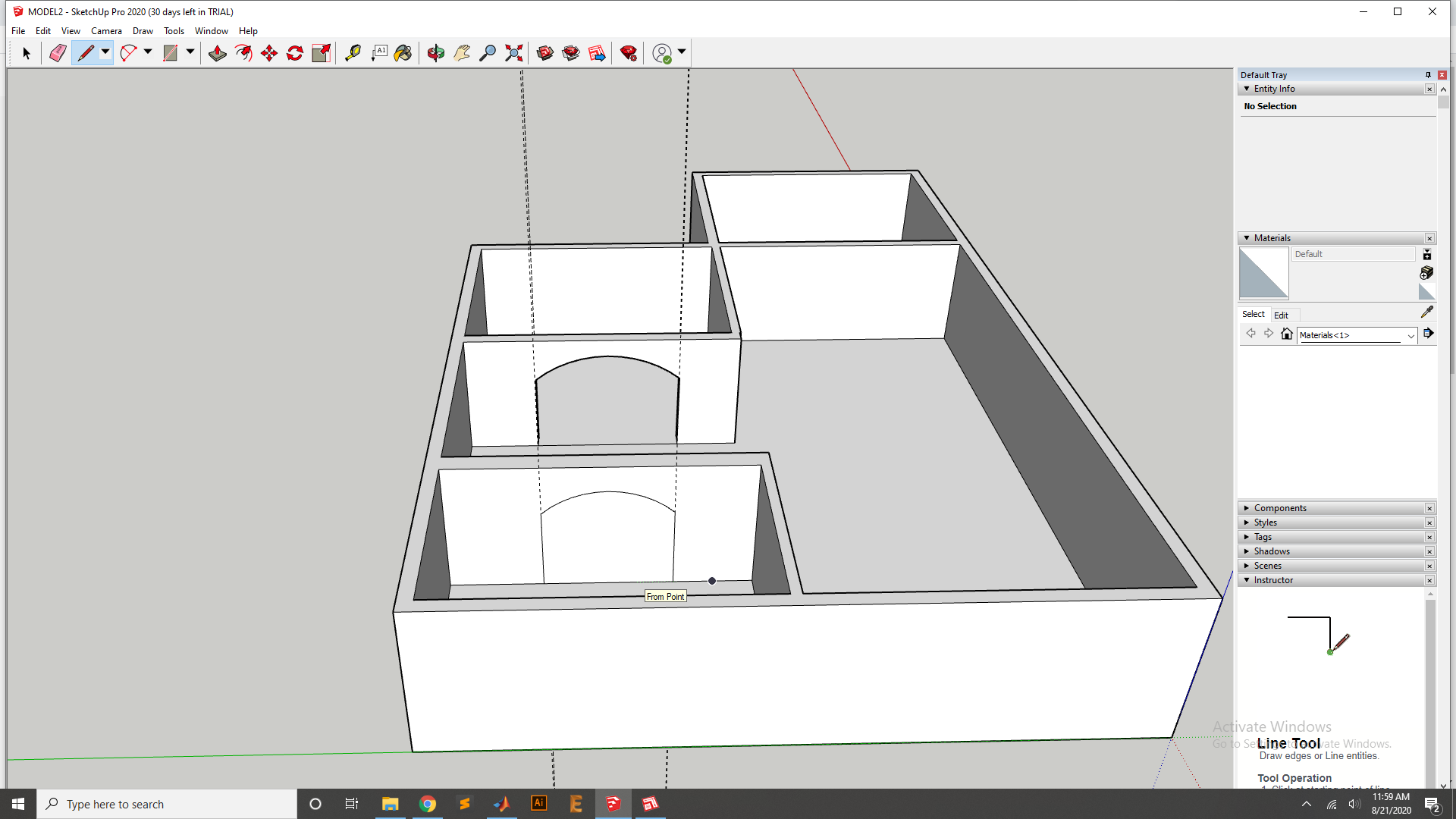
Now Extrude cut it.
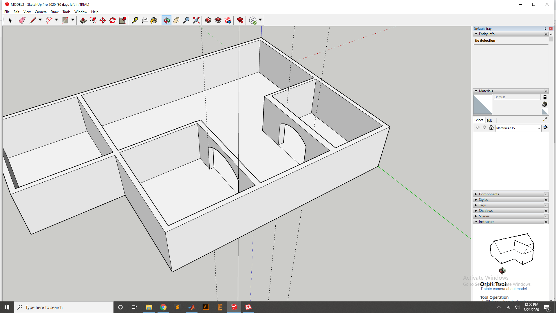
Now add the small Room.
Add the Door with room third using the Pen for drawing and extrud Cut.
After the extrude cut it looks.
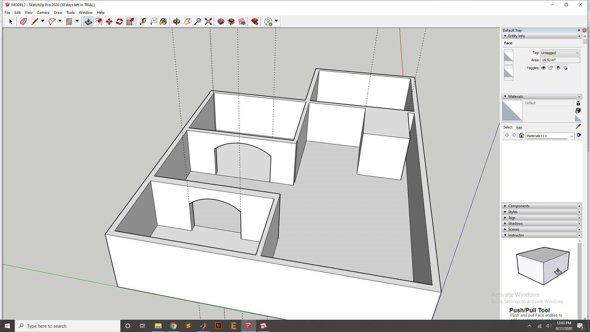
Now phase is to add the Window so first I Draw the Design of window by using Pen.
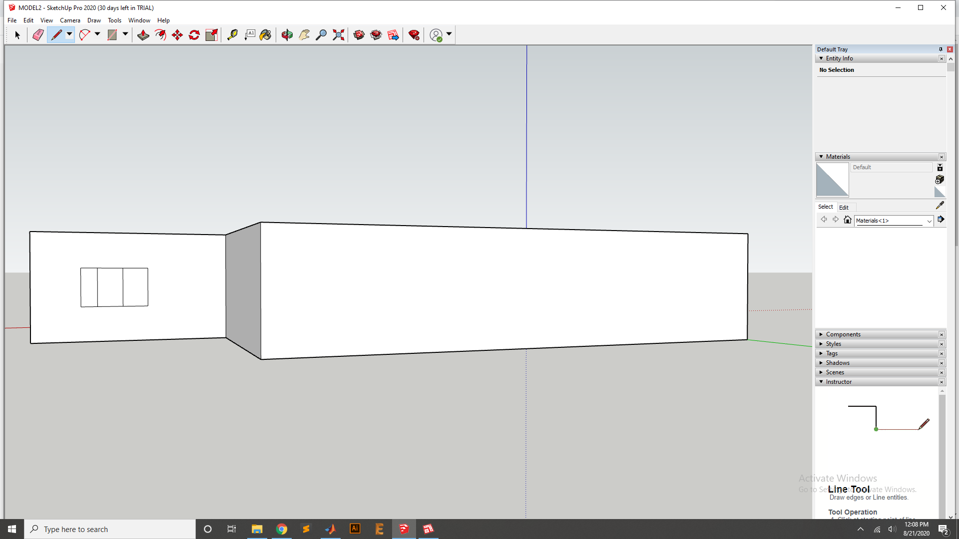
Now use the extrude tool to cut the Extrude cut.
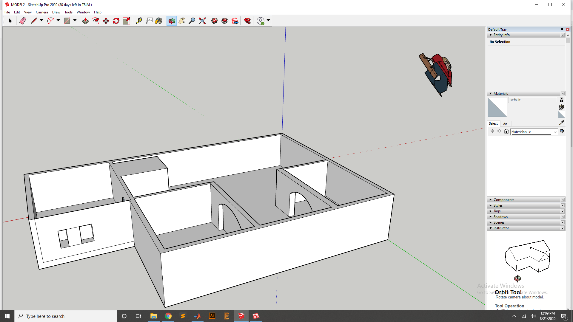
Window design for other side using same process.
Final Design looks.
Design In Free CAD
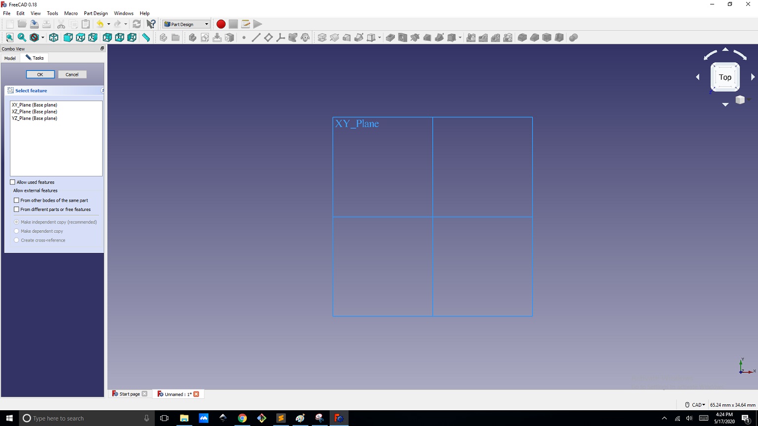
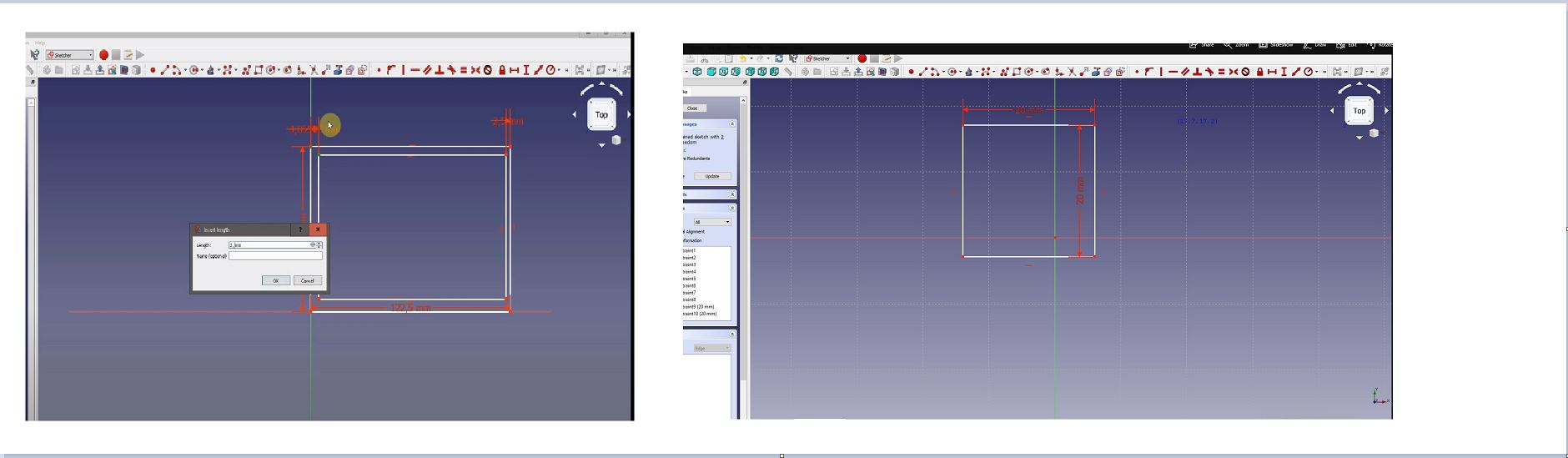
In this Assignemnt I have used free CAD Saftware , and it is Downloaded from Here and Install It in PC. after That I have Designed the Box with size of 20mm, 20mm and 20mm.
First I set the axiss in free CAD
Then Create the Box in Free CAD
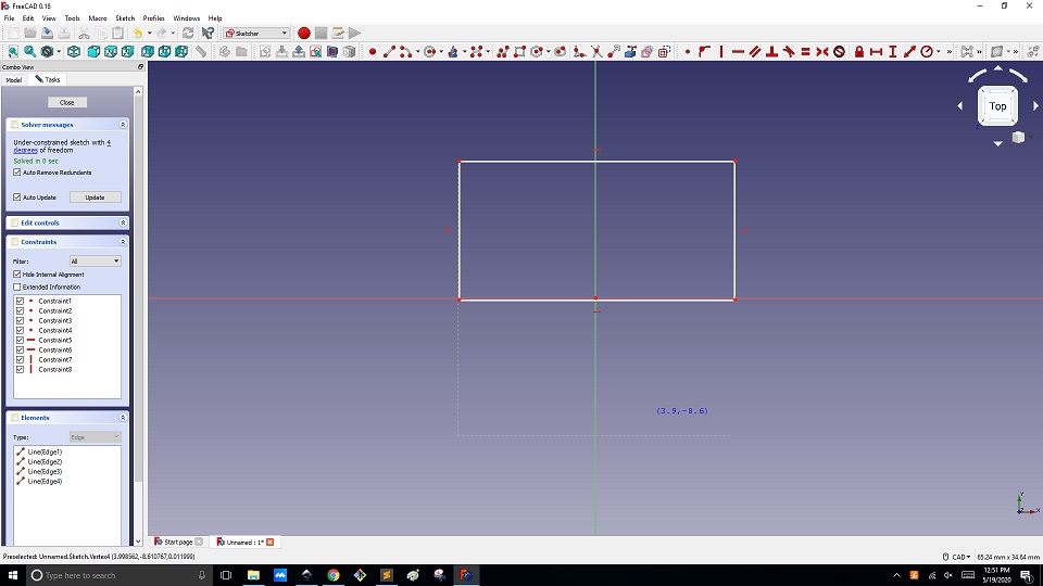
Now the Box Measuremnets
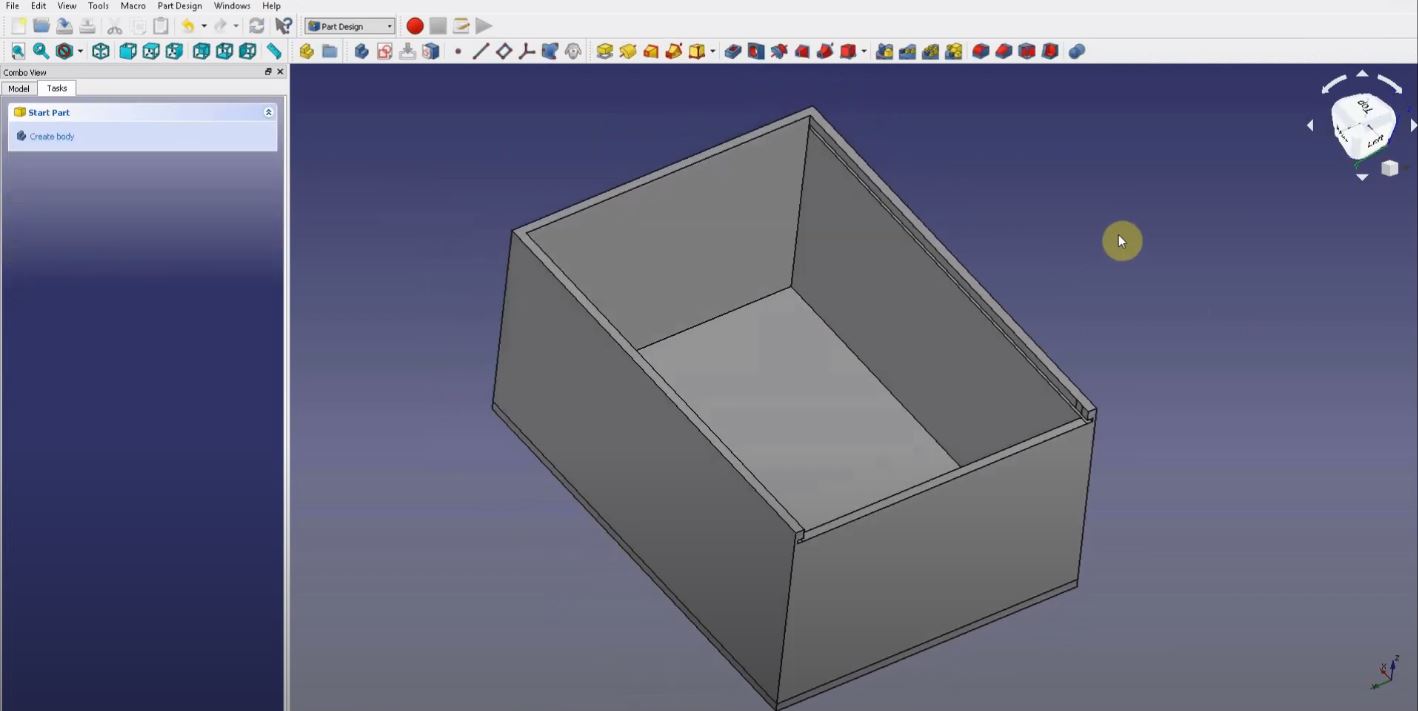
Now this is the Final BOX That I Have Designed
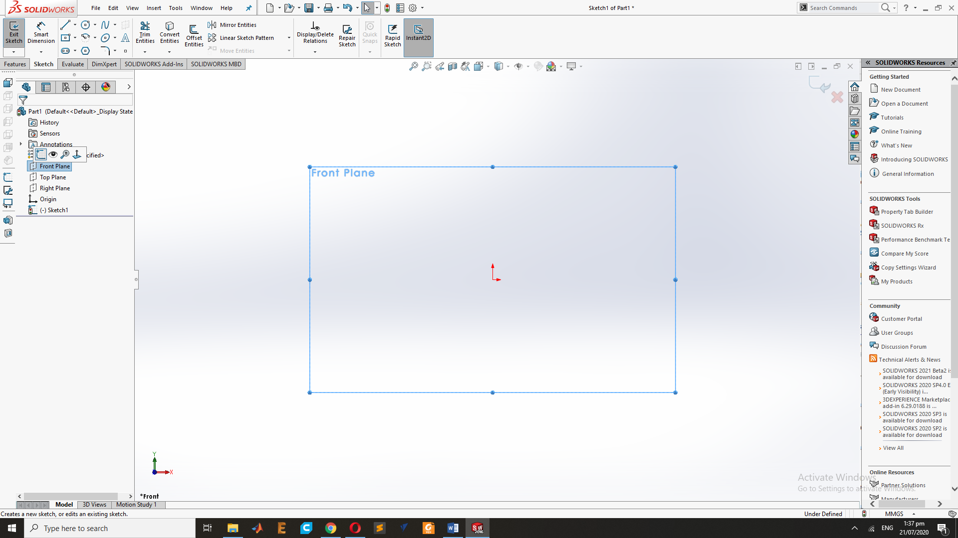
Design In solid Work:
First Set the Plan for the Drawing.
Second I Select the Rectangle and draw Two Rectangle on the Plan.
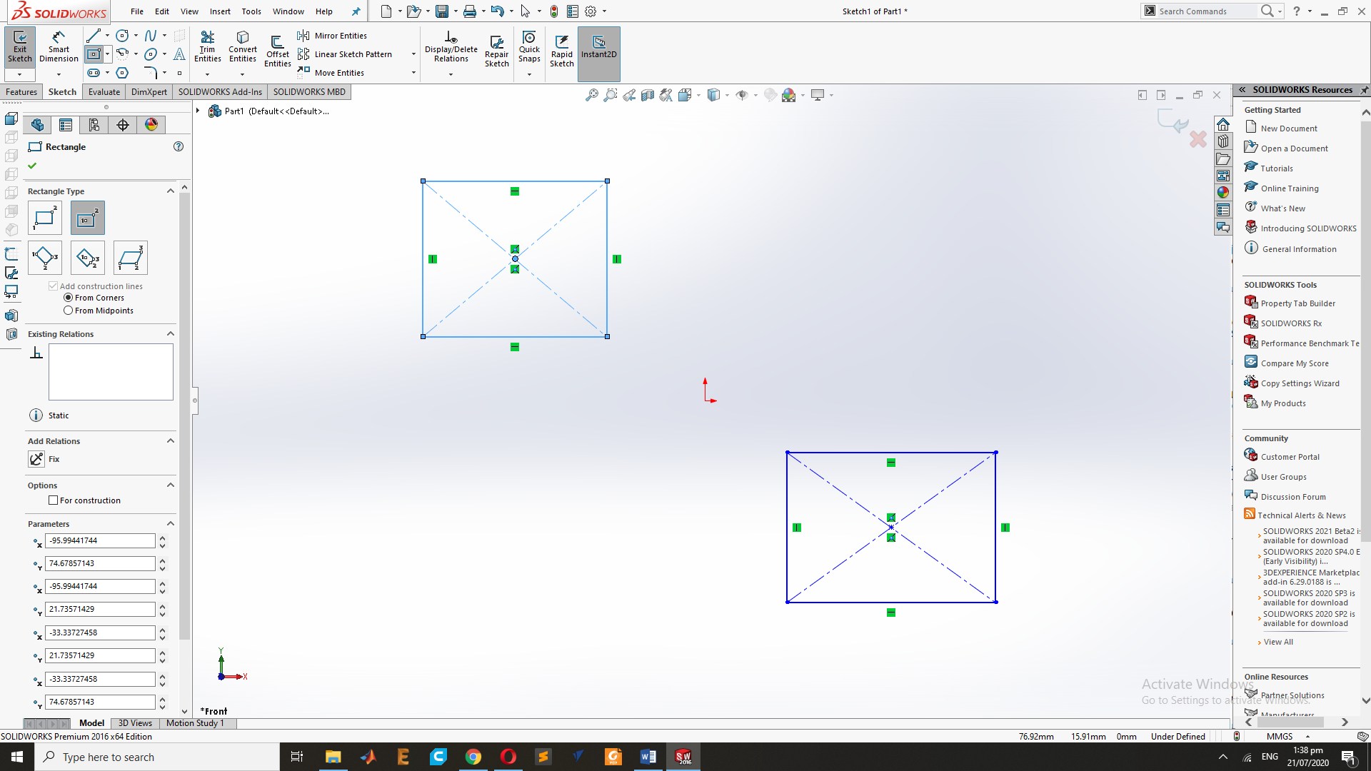
Now Extrude the Rectangle with Extrude Command :
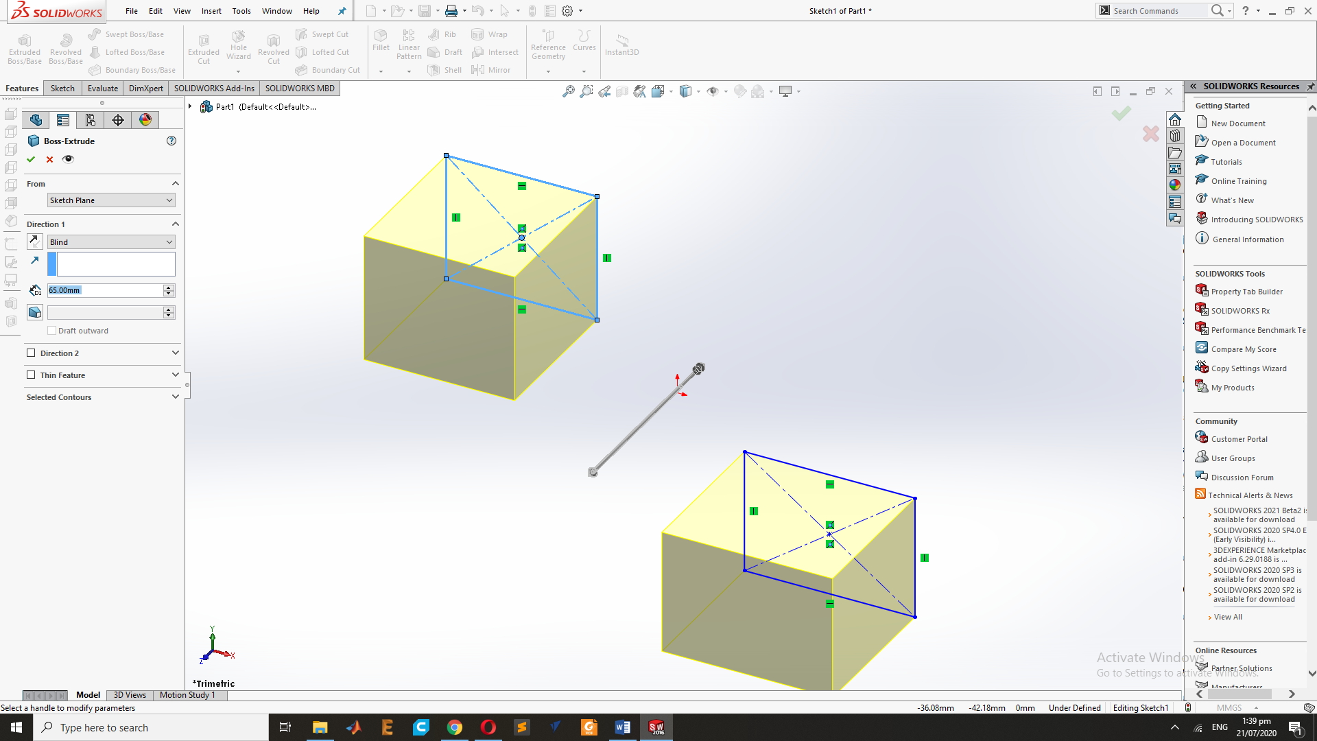
This is the Design of two rectangle
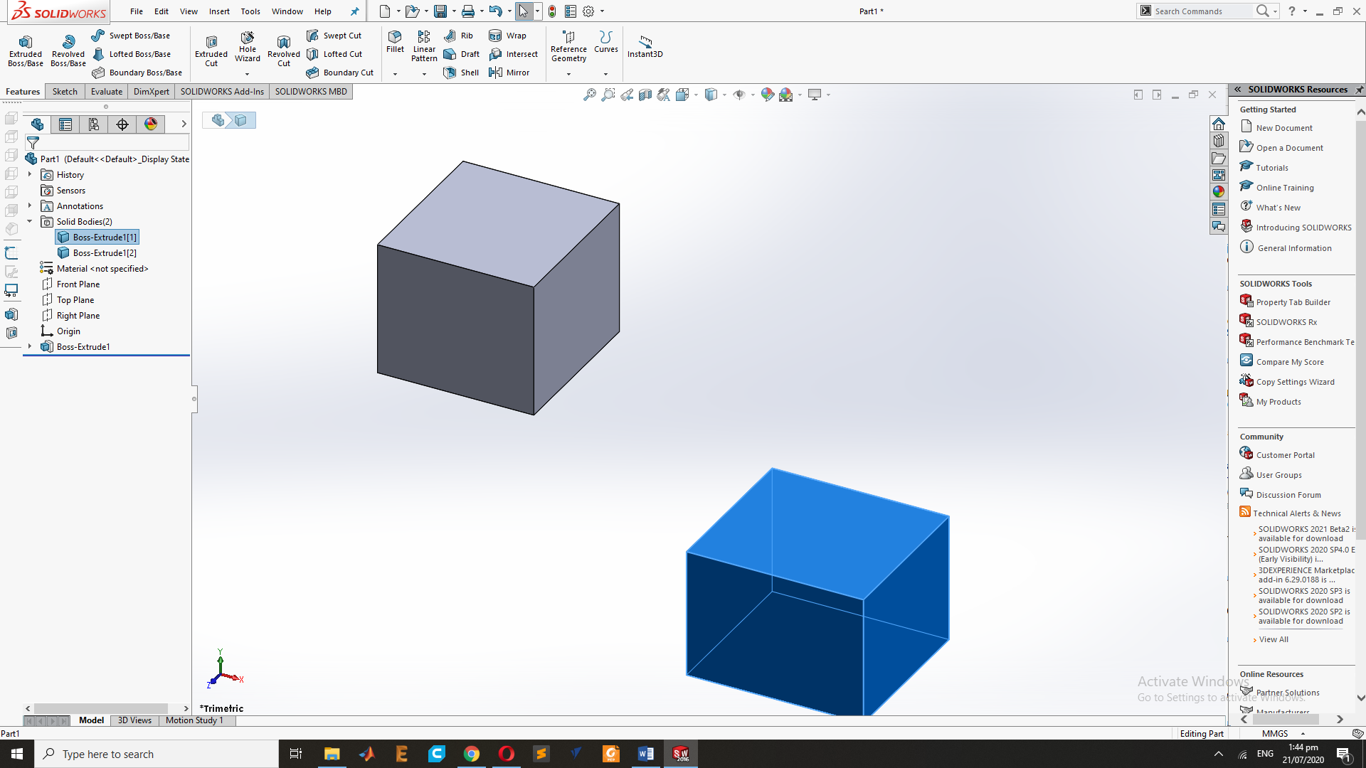
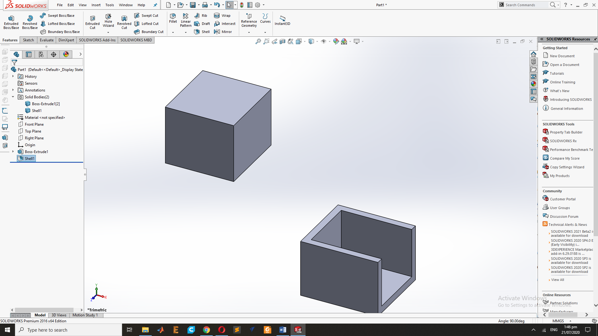
Now I have Select two side of Rectangle and use this Shell command.
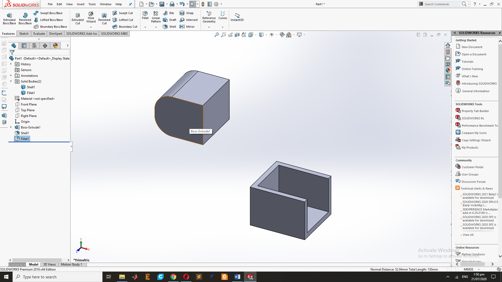
Now Goes to fillet command and fillet two side of the second Rectangle.
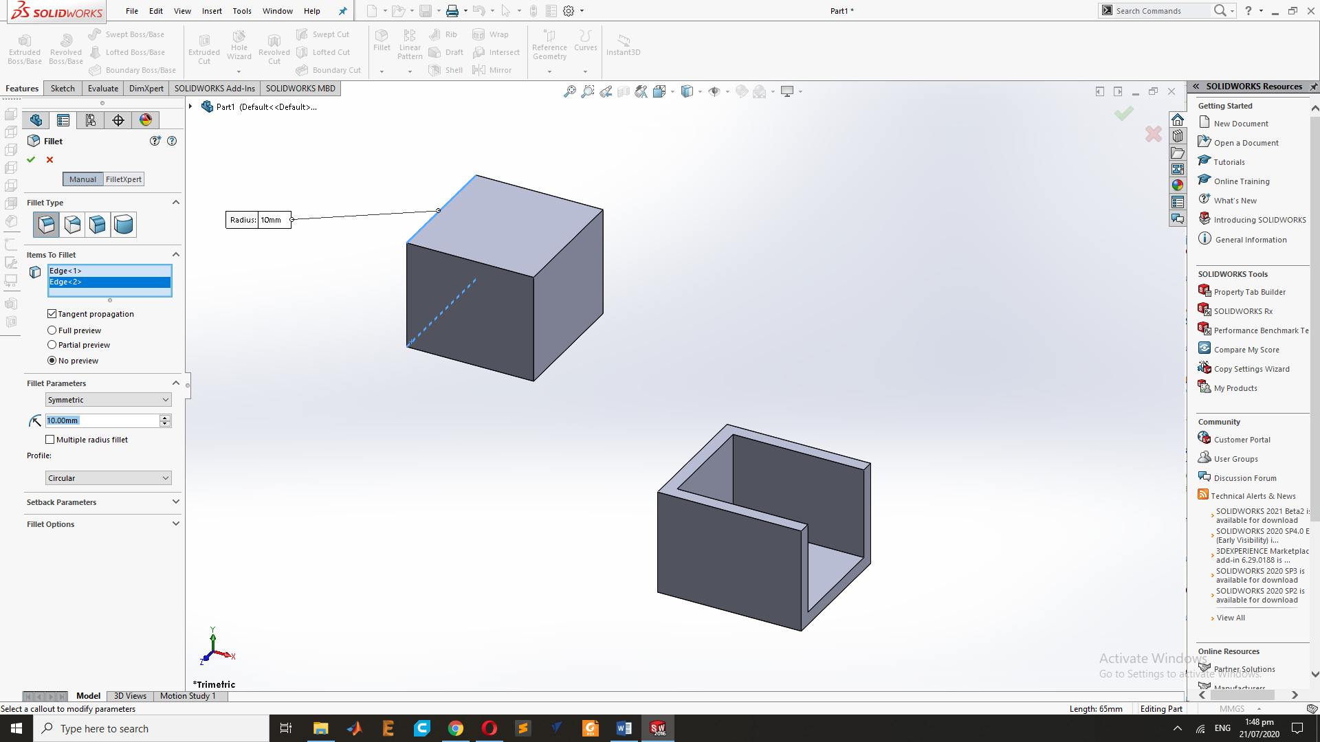
After the Fillet Command Result:
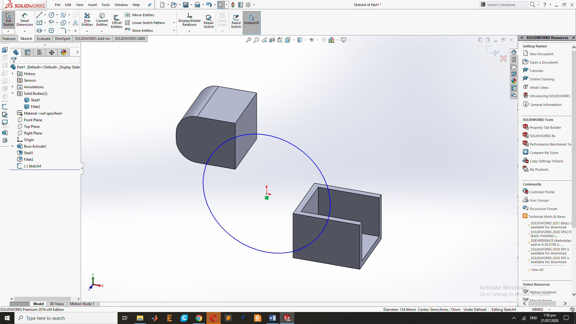
Now Draw the Circle Between the Sheel and Fillet Rectangle design.
Now Extrude the Circle .
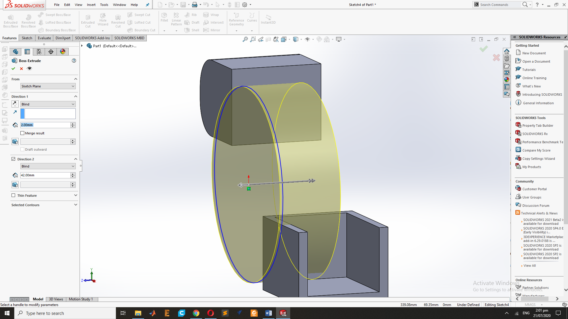
This is the Final Result of the Extrude of Circle.
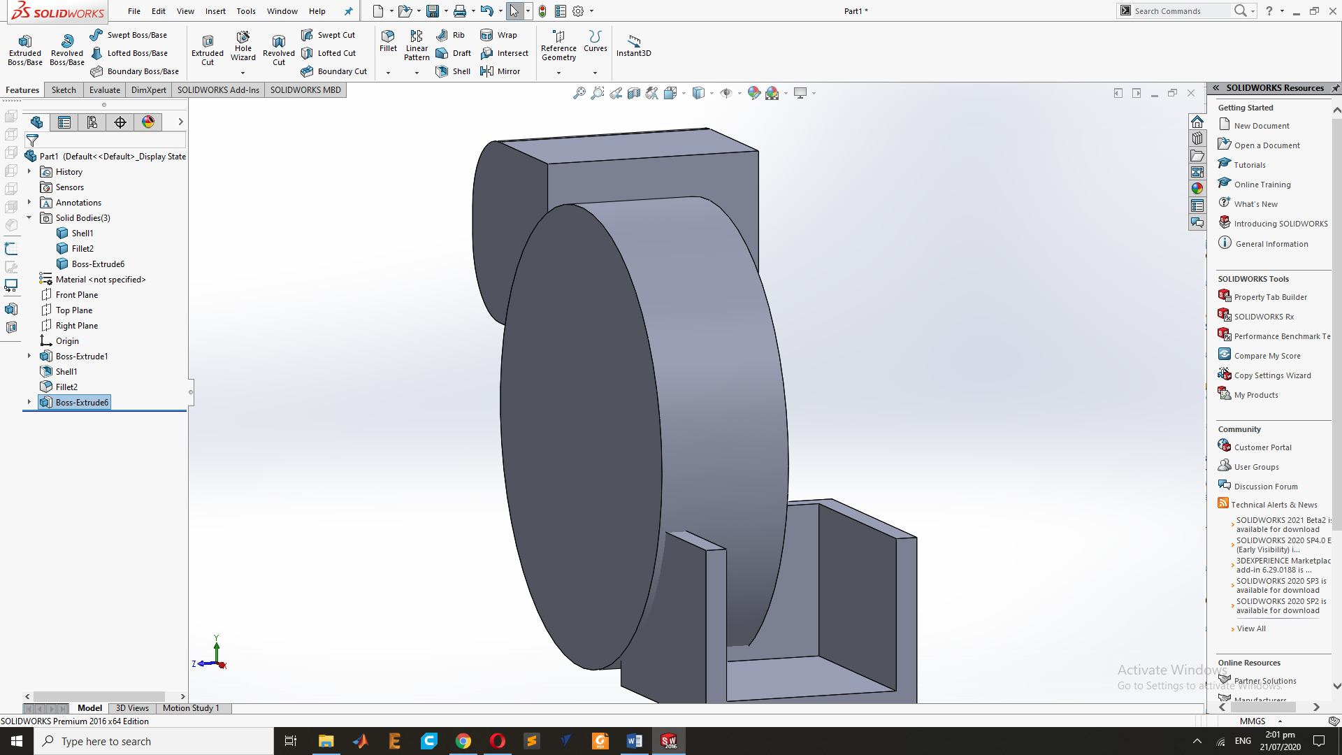
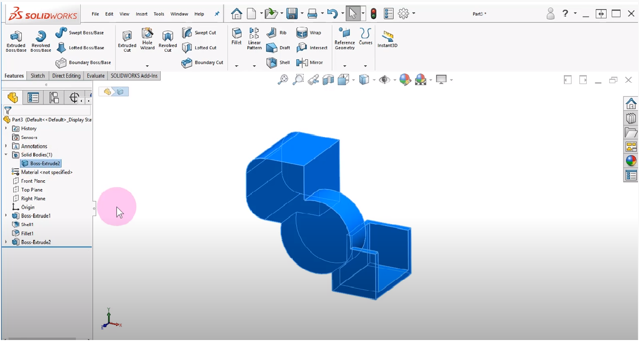
Now merge to all Design and its Look like that.
Now I will remove the Circle by using the extrude Cut.

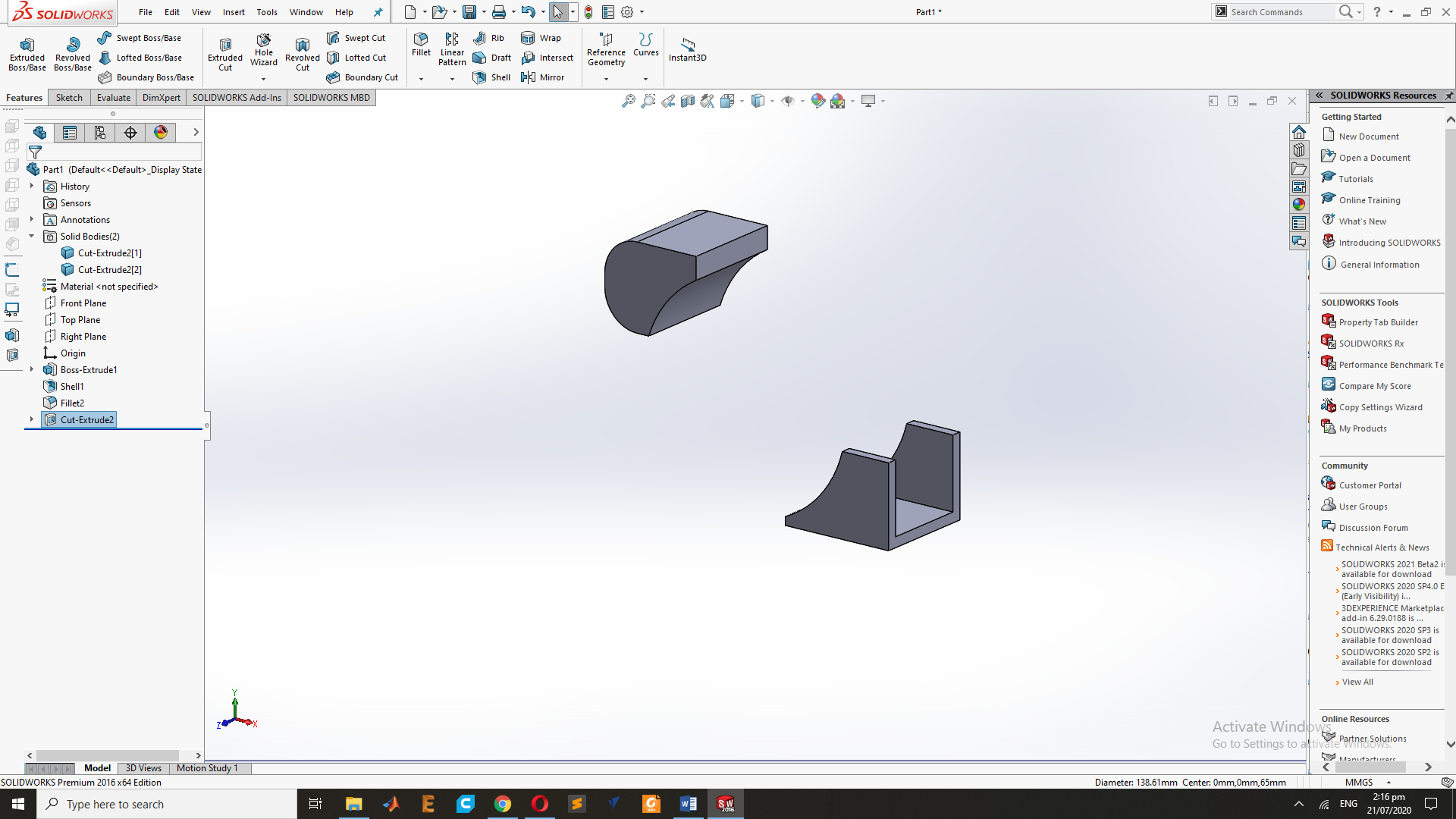
After the Extrude cut my Design looks.
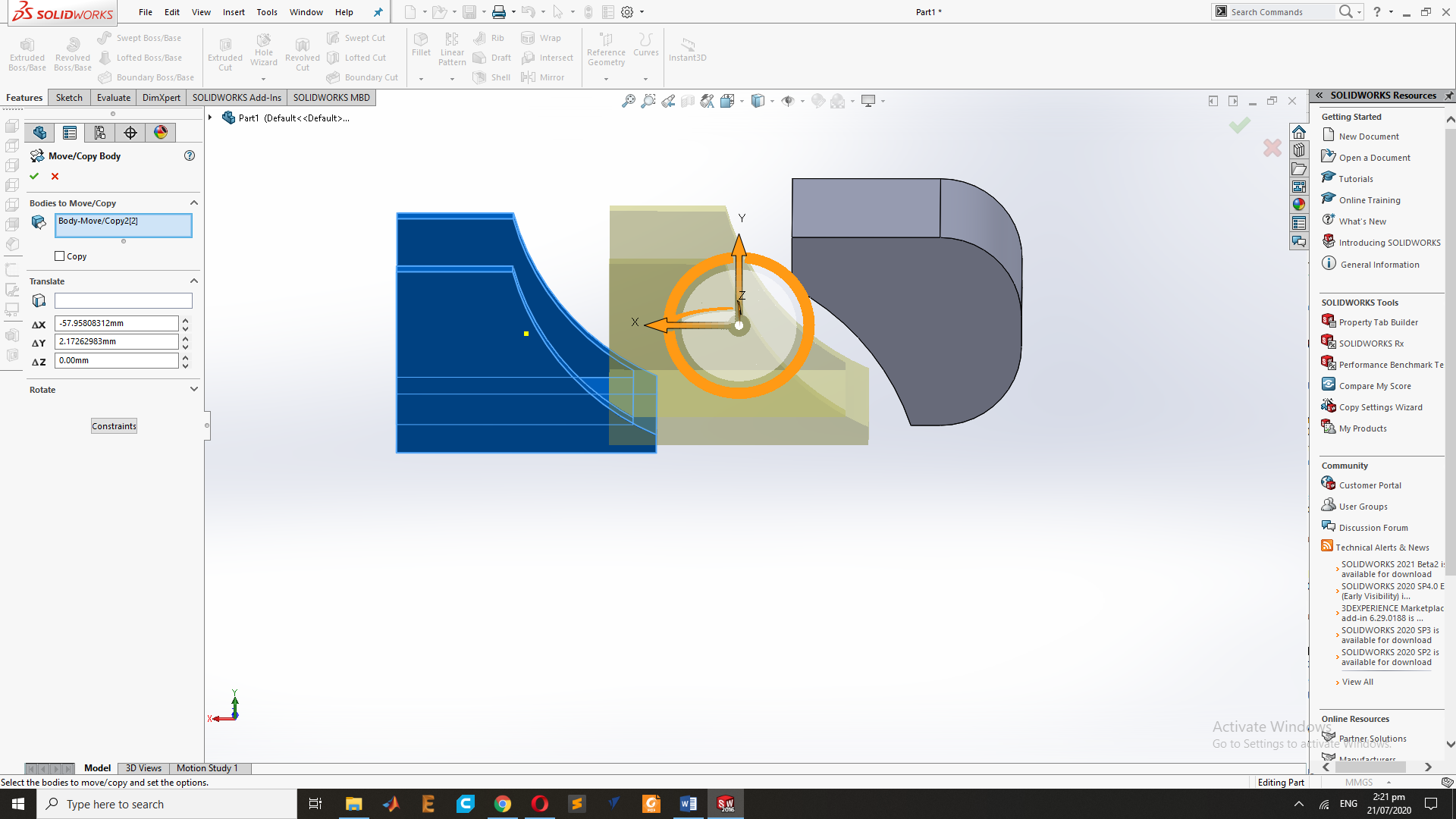
For the Move of Object, Goes to Insert and Select the Move and copy Command to Move the Object.so While Moving.
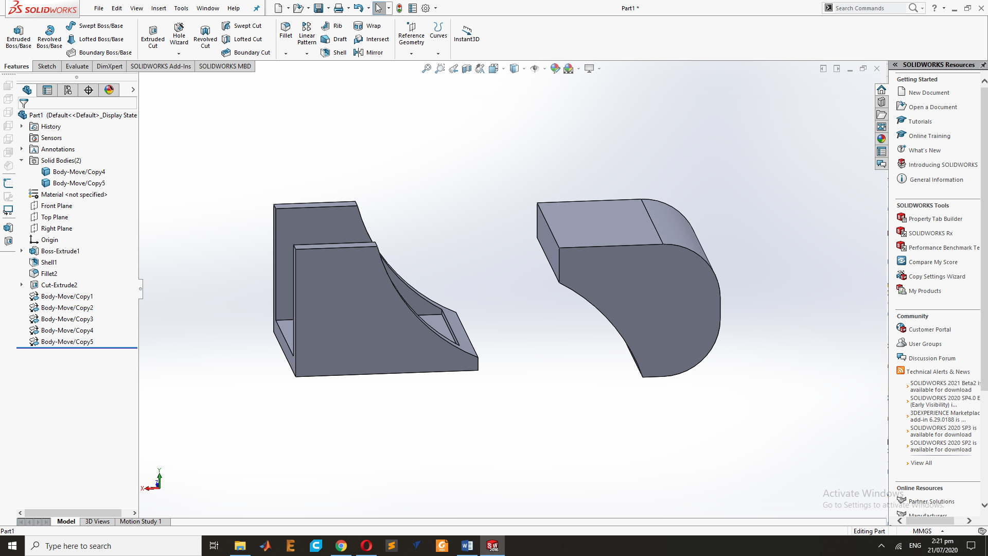
Final Result of the Design .
Conclusion
This week I have learn about 2d and 3d design ,the Raster and Vector Images and Parametric and non Parametric design. and use the Different CAD software for the CAD Design.

This work is licensed under a Creative Commons Attribution-NonCommercial-ShareAlike 4.0 International License
.