Project
Final Project
Midterm Proposal (application implication, week09)
I reviewed the past 9 weeks activities and embodied my plan to final project as an outcome from assignment of propose a final project masterpiece (week10).
Table of content
- Scope of final project - As of 1 May 2020
- What will it do?
- Who's done what beforehand?
- What will you design?
- What materials and components will be used?
- Where will come from?
- How much will they cost?
- What parts and systems will be made?
- What processes will be used?
- What questions need to be answered?
- How will it be evaluated?
- Bill of materials (May 2020)
- Project Planning
- Final project schedule (as of 18 April 2020)
- References
What will it do?
Like cooking and eating “Nabe(鍋, hotpot in Japanese)”, players can play rhythm sequence (or more sound patterns) just by putting things on the surface of the instrument device.
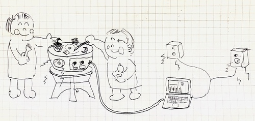
Anyone can:
- play easily - simple interface
- play with anyone - multiple player
- play anywhere - portable
Who's done what beforehand?
- James Fletcher, FA2014 made an Attiny44 based sound modular device
- Fiore Basile, FA2014 made a tiny MIDI device as an artifact of "input device" week.
- Xiaofei Liu, FA2019 made a disc player that can translate graphics into music!
- Deepti Dut, FA2017 who made Soft MIDI Controller explains about the coordination via Device - loop MIDI - SerialMIDI - DAW(Ableton)
- Rectable(youtube video) is the one that put object and make sounds with more highly graphical and complex way.
- This youtube video explains how to change Arduino device as an USB MIDI Device updating the firmware using "Arcore" library
- A youtube video of DIY Arduino MIDI controller project explains how it works and how to make it.
I want to add my idea of "making sounds by just putting object" to above existing excellent projects.
What will you design?
Based on consideration and experiment thorough 9 weeks including Neil's review, I re-designed architectural overview ver. 0.2 that I had started.
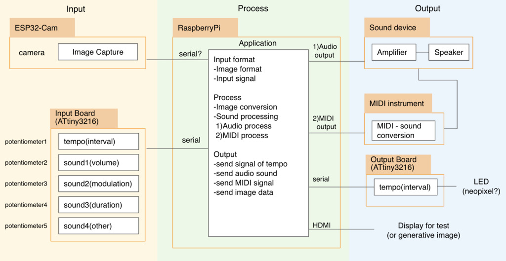
What I will design are as follows.
Hardware
Pot
_x600_FAweek2_20200211.jpg)
- Outline of the instrument - refine and resize the image of final project round 2(outline design). Pot will be made by MDF(4mm) and cut subtractively by a laser cutter
Parts: acrylic table and stopper
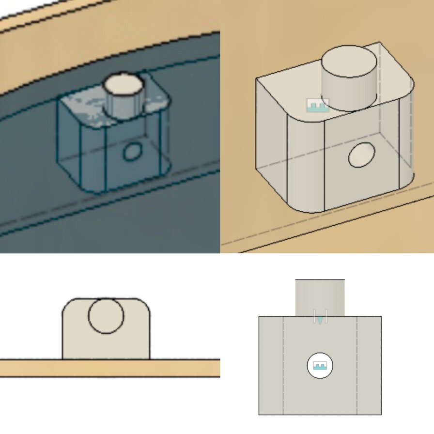
- Transparent top table made by 5mm acrylic (clear). The table will be cut subtractively by a laser cutter.
- Pot has an acrylic top table to put the object on. Though the past designed image in week 2 has a tiny protrusion that penetrates acrylic table, it's good to change it into screw to fix the table to the body.
Parts: knob for potentiometer
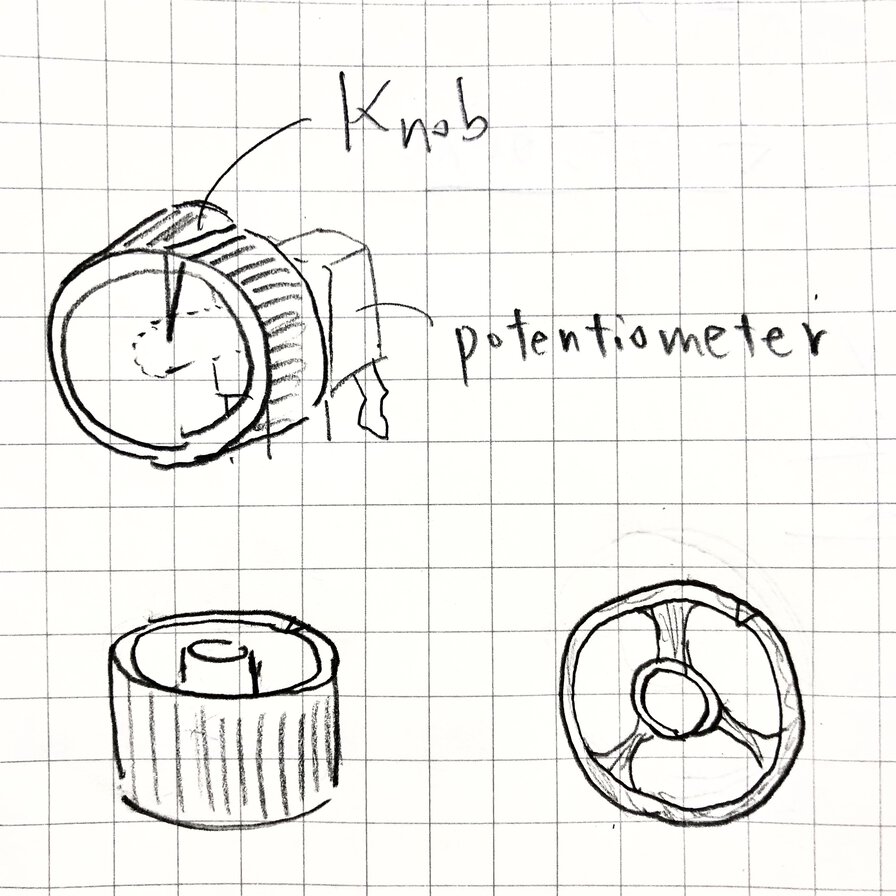
Knob for potentiometer will be printed additively. For putting on the surface of outline of "Pot", it's necessary to be tiny and to fit with the volume knob of potentiometer.
Boards: Input/Output Board(ATtiny3216)
Schematic and board image that has joint to connect with potentiometers and LED array(NeoPixels) over serial communications
Boards: Application Board(Raspberry Pi)
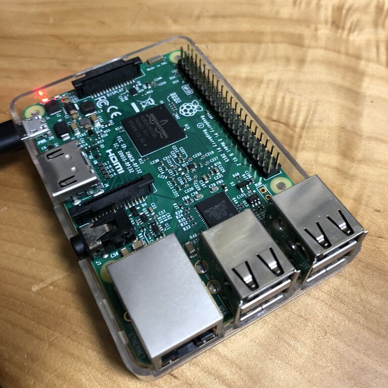
processing images and sounds data interactively
TO DO: check the spec of the other revision of Raspberry Pi like Raspberry Pi zero. If it's enough to process the application by tinier one, that would be better.
Sound devices: amplifier

Acquired a small digital amplifier for concentrating on input/output signal conversion and application process including image conversion and audio/MIDI output. Need to revise that from stereo mode into monaural mode.
Sound devices: speaker
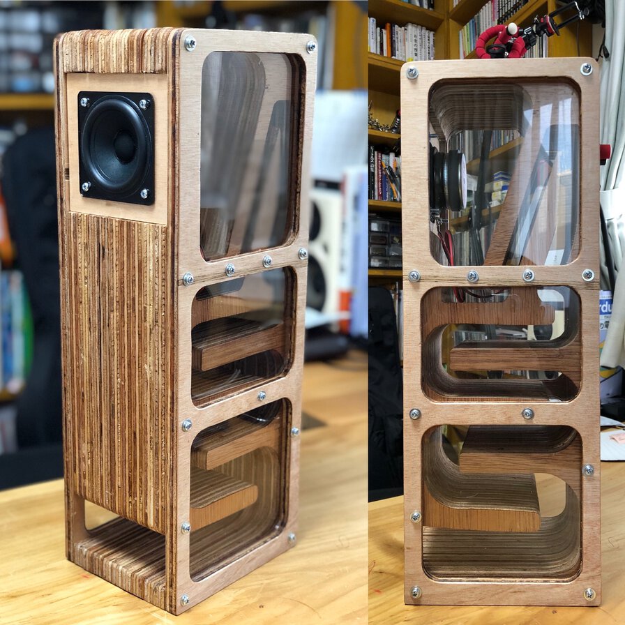
Designed, milled and assembled a backload horn speaker as an outcome from computer-controlled machining week.
Software
Input
- ESP32-Cam
- the way to configure camera settings
- the way to capture image for each interval configured by a potentiometer
- the way format data for transmitting to application
- Input/Output Board(ATtiny3216)
- Reading and sensor values from potentiometer
- the way to transmit "interval" to capture image to ESP32-Cam
- the way to transmit sound configuration to application
Process
- Application(Raspberry Pi)
- The way to receive input and format data
- Process to convert image and generate sound by audio or MIDI signal
- Output processed data of signal of tempo, audio sound, MIDI signal and image data(in display for test)
Output
- Input/Output board(ATtiny3216)
- Receive a signal of tempo(interval)
- Process received data into signals to make optical output
- The way to output processed data and blink LED array
- Sound device
- N/A(Amplifier and audio output will not need software implementation)
- MIDI instrument
- The way to receive MIDI input
- The way to process it in web MIDI or the other way to make sound(like solenoid output)
NeoPixel can be controlled by only 1 I/O pin of microcontroller (Ref: experiment to embed controlling program to ATtiny3216). So, it would be enough to have 1 ATtiny3216 based board for controllign input of potentiometers and LED array.
What materials and components will be used? / Where will come from? / How much will they cost?
Bill of Materials
ESP32-Cam (*)
There is an alternative of ESP-WROOM-32D + Camera module
| Material | Amount | Price | Source | Memo | DiyStudio ESP32 Camera module | 1 | 1240 yen | Amazon.co.jp |
|---|---|---|---|---|
| Summary | 1240 yen |
Raspberry Pi
| Material | Amount | Price | Source | Memo | Raspberry Pi3 Model B | 1 | 5590 yen | Amazon.co.jp |
|---|---|---|---|---|
| Summary | 5590 yen |
Input/Output board
| Material | Amount | Price | Source | Memo |
|---|---|---|---|---|
| Potentiometer | 5 | 270 yen | Monotaro | 54 yen/1 |
| LED neopixels(WS2812BECO White PCB) | 1 | 1076 yen | AliExpress | 1m 144 IP30 |
| Angle Pin Header | 1x6(FTDI)+1x2(UPDI) | N/A | Digikey | 492 yen for a set |
| FR1(phenolic paper) | 1 | 180 yen | marutsu | カット基板 銅張積層板 片面 紙フェノール 100×150×1.6mm【NO12】 |
| Cable | 15 cm | N/A | DigiKey | (MC10M-50-ND) |
| Summary | 2487 yen |
Sound device(Amplifier)
| Material | Amount | Price | Source | Memo |
|---|---|---|---|---|
| Digital Amp board(HiLetgo® YDA138 2 * 10W Dual Channel Digital Amp DC 9-14V) | 1 | 870 yen | Amazon.co.jp | |
| AC Adapter(Punsai Charger 3V-12V voltage adjustable) | 1 | 1190 yen | Amazon.co.jp | |
| Audio jack socket adapter, triple-pole, female | 1 | 200 yen | Amazon.co.jp | |
| AC adapter socket adapter | 1 | 53 yen | Unknown | Ref: Amazon.co.jp |
| Summary | 2313 yen |
Sound device(Speaker)
| Material | Amount | Price | Source | Memo |
|---|---|---|---|---|
| Lauan plywood, 12mm thickness, 910mm x 1810mm | 1 | 1850 yen | CAINZ Hamamatsu Yuto | |
| Acrilic (transparent), 5mm thickness, 300mm x 450mm | 1 | 1000 yen | Stock at Fablab Kannai | |
| Speaker Unit(FOSTEX P800K) | 1 | 1236 yen | Amazon.co.jp | |
| Speaker cable, 0.3mm^2 x 2C | 30cm | 300 yen(5m) | 秋月電子(akizukidenshi) | |
| Speaker terminal | 1 | 600 yen (per 1 part) | (2 parts 1200yen) Amazon.co.jp | |
| Insert nut(鬼目ナット), M4 x 10mm | 28 | 890 yen | (6 pieces * 5 pack)CAINZ Hamamatsu Yuto | |
| Pan head screw(鍋ネジ), M4 x 25mm | 28 | 255 yen | (10 pieces x 3 pack)CAINZ Hamamatsu Yuto | |
| dowel(ダボ), 6mm | 8 | 118 yen | (10 pieces) D2 (ケイヨーデイツー) | |
| glue for wood | 1 bottle | 88 yen | Stock at Fablab Kannnai | |
| Sand paper(#120, #240, #2400) | 5 | 150 yen | CAINZ Hamamatsu Yuto | |
| Oil (Osmo color, clear) | around 100ml | 600 yen | Tamura lumber dealer | |
| Solder | a bit | N/A | Stock at home | Monotaro, 869 yen/reel |
| Summary | 7087 yen |
(*)ESP32 Cam vs. ESP-WROOM-32 + Camera module
ESP32 Cam is not applied a "certification of conformance to technical standards(技適: 技術基準適合証明)" in Japan.
1st is to use the original ESP32 Cam provided by AI Thinker as ESP32C-S microcontroller looks to have the "certification of conformance to technical standards" in Japan. However, every case that I could check in internet did show "over Wifi" use case not the case of simple serial communication.
Though I've not figured out the interface design of Camera - microcontroller - application(Raspbrerry Pi) at this point, my sound device needs to be packed as a portable instrument and I do not need Wifi camera server in "Pot" because I do not want to depend on Wifi environment. Instead, I need a simple way to like serial interface.
2nd option is using ESP32-WROOM-32 + camera module like OV2640. That composition has been applied the "certification of conformance to technical standards" in Japan(技適取得済). Also, there are some cases of simple composition to interface over serial port over UART. If takes this option, following parts will be needed.
Ref: Try to make ESP-WROOM-32 into DIP kit
(Option)ESP-WROOM-32 + Camera module
| Material | Amount | Price | Source | Memo | ESP32-WROOM-32D Wi-Fi + BLE module | 1 | 670 yen | Akizukidenshi.com | OV2640 2M pixel camera B0011 | 1 | 1180 yen | Akizukidenshi.com | CMOS regulator 3.3V 500mA | 1 | 50 yen | Akizukidenshi.com | NJU7223F33 | electrolysis condenser 47μF35V、85 degree | 1 | 100 yen | Akizukidenshi.com | 100yen / 1 pack(10) | ceramic capacitor 0.1μF 50V 2.54mm | 1 | 50 yen | Akizukidenshi.com | carbon resister (1/4W 10kΩ) | 1 | 100 yen | Akizukidenshi.com | 100yen / 1 pack(100) | tact switch | 1 | 10 yen | Akizukidenshi.com |
|---|---|---|---|---|
| Summary | 2160 yen |
What parts and systems will be made? What processes will be used?
Except the materials for each component above, I made some hardware parts and systems as follows.
Hardware parts
| device/parts | what to make | what to use/buy alternatively | What process will be used |
|---|---|---|---|
| "Pot" | outline, joints and acrylic table | (N/A) | 2D/3D design and cut materials by laser cutter. |
| Stoppers for acrylic table | stopper x 5 | screws | 3D design and 3D print |
| Knob for potentiometer | Knob x 5 | (N/A) | 3D design and 3D print |
| Input/Output board | a board converter(FTDI-USB(?)) and cable | AC adapter jack, AC adapter, battery cable, spacers and screws for fixing board. | Design schematic and board images, mill and assemble |
Software system
| Component | what to make | what to use | What process will be used |
|---|---|---|---|
| Image Capture(ESP32-Cam) | A program to configure image sensor parameters, capture image and transmitting program from OV2640 camera module to ESP32, then send it to Raspberry Pi by some protocol like Serial(UART) or other network protocol(to be determined as of 13 April) etc. | ESP32 camera library | Arduino language program on Arduino IDE |
| Input/Output board progarm(ATtiny3216) |
|
Adafruit_NeoPixel library | Arduino language program on Arduino IDE |
| Application(Raspberry Pi) |
|
Python on PyCharm IDE |
What questions need to be answered?
- How do you assemble the shape of "Pot"?
- I design joints with good press fit by considering kerf of laser cutter.
- For recognizing the position of object, why do you want to analyze image instead of multiple options like RFID, Cap response or light sensor?
-
I choose camera as image sensor device and analyze that in library in open cv and midi python library on Raspberry Pi, that is common way to capture images.
Or, it might be possible to do image process and make it into MIDI in arduino libraries on ESP32 (To be determined as of 13 April).
Alternative devices and evaluation (the reason why I did not chose these input devices to capture the object shape).
input device what and how to capture the object shape evaluation RFID proximity with tag in object side requiring tag in object side, it's not relevant to the solution for "putting anything and capture the shape" Capacity Respose step response by current amount by touching requiring bio-metrics that can hold current like finger touch or water etc, it's not relevant to the solution for "putting anything and capture the shape" Light sensor/photocell sensor brightness captured by light amount responding to resister value, or color using resonating LED color It’s difficult to capture multiple detail segmented position ( imagine that 50 beans are thrown on the table and you want to capture positions or each bean and change them into MIDI signals. It could be done by 50 photocell sensors on the table, but I do not think it’s intelligent). - What's the role of microcontoller?
- Read sensor values, send it over serial interface to central application, and calcurate and write output value.
- Why do you chose Raspberry Pi for application processor?
- Image processing requires payload of microcontroller. Also, for making MIDI object and interface, I want to use python libraries that can be embedded on Raspbian OS.
- Why do you use ESP32 and camera module by serial interface instead of web camera or the other network protocol?
- It's because I want to avoid latency bottleneck of streaming image process over Wifi environment. However, ESP32 camera library looks to have multiple track records on network camera rather than line connected camera module. As of 14 April, it's still under consideration.
How will it be evaluated?
- Can player make rhythm sequence (or more sound patterns) just by putting things on the surface of the instrument device?
- Can it be played easily with simple interface using potentiometer and putting things?
- Can it be played by multiple players?
- Is this a portable device?
Project Planning
- 1st Spiral
- Input/Output breakout board at least one potentiometer and switches - (USB Serial interface) - Raspberry Pi to receive and send back valuses
- Raspberry Pi camera module - Raspberry Pi to capture and store it to local SD card
- Raspberry Pi audio interface - audio output to make simple sound using MIDI library and software synthesizer on RaspPi.
- 2nd Spiral
- Input/Output breakout board with multiple potentiometers and switches - (USB Serial interface) - Raspberry Pi to receive and send back valuses
- ESP32(+Cam)(Or RaspPi Cammera) - Raspberry Pi to process streaming images, capture it for each interval value from potentiometer and convert image information into parameters of MIDI object.
- Raspberry Pi audio interface - audio output to make sound using MIDI library and software synthesizer on RaspPi.
- 3rd Spiral
- Assemble hardware and finalize application for rhythm sequencer.
- + Optional, if possible
-
- Make generative optical art by processing
- MIDI output device using solenoid.
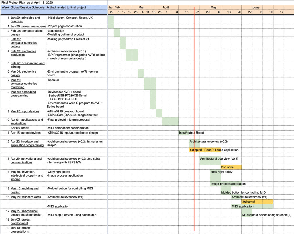
Final Project Schedule as of April 18 2020
