Assignment
Week7: Computer-Controlled Machining
Assignment
- group assignment
- test runout, alignment, speeds, feeds, and toolpaths for your machine
- individual assignment
- make (design+mill+assemble) something big
My Work
I've learned about large CNC at Fablab Hamamatsu and created my original backload horn speaker for an assignment of "making something big". That can be used as a part of my final project.
Group Assignment
test runout, alignment, speeds, feeds, and toolpaths for your machine (link )
Idea
As my final project is making sounds, I came up with idea that I will make a "something big original speaker".
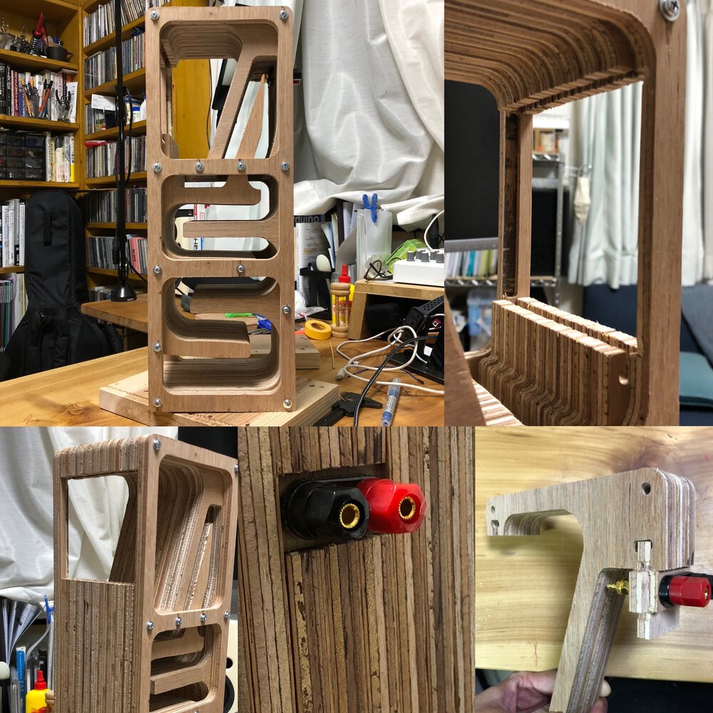
Though it's my first time to make speaker, I challenged to make "backload horn" typed speaker that can emphasize low tone by stretched horn from back side of speaker unit. It's good chance to design and cut complex curve using large CNC and joint it tightly not for leaking noise.
Design
Research
I have a set of speaker unit for entry DIY kit - FOSTEX P800K and want to use it.
While checking manual of P800K, I serached the way to make a backload horn speaker like:
- youtube video by Super Techsan who made a backload horn speaker by tip saw and router.
- BH型スピーカーを設計しよう ~その2 (空気室編)~(Japanese: Let's design BH type speaker 2: Air chamber)
- Youtube video by Mr. ICHIKEN
- Eduardo Sogovia in FabAcademy 2019 made a speaker and amplification device as an assignment of output device
Calculation
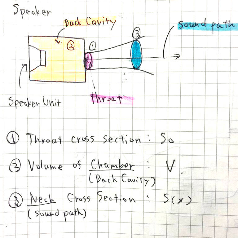
According to above reference website and youtube videos, some says important design elements of BH speaker are:
- So: Throat cross section on the back cavity of speaker - the cross section of the starting point of back horn
- V: Volume of back cavity(chamber)
- S(x): Neck(Sound path) crosssection area - more stretching neck(sound path), more larger cross section area.
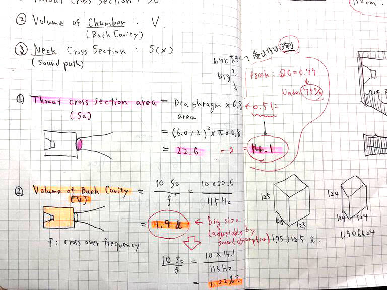
1. So(Throat cross section) = "Diaphragm area of speaker(スピーカーの振動面積)" x 0.5(this is defined by Q0(振動先鋭度) of speaker(according to rule of thumb...see here(Japanese))
2. V(Volume of back cavity) = 10 * So / f (cross over frequency of speaker))
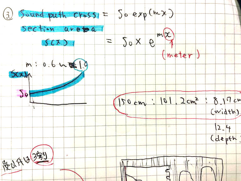
3. Sx(sound path cross section area)V(Volume of back cavity) = So * exp ^mx
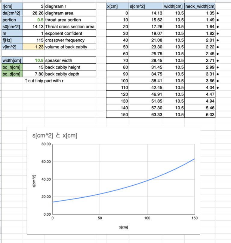
I tried to check different portion, speaker width and size of back cavity using spreadsheet. Longer horn is better for sound but also I want make my speaker not too big.
Finally I calculated and decided So(throat cross section area), back cavity hight, back cavity depth and exponential neck width per 10 cm of neck.
2D / 3D Design
As I want to make parametric design that can absorb the change of material(thickness etc.) and the other important design like depth of slit, I used Fusion360 and its user parameters.
Procedure of making backload horn shape
.png_1000x_q85.jpg)
.png_1000x_q85.jpg)
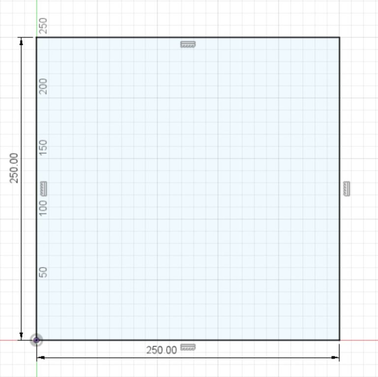
Outline shape of speaker
_many_constraint.png_1000x_q85.jpg)
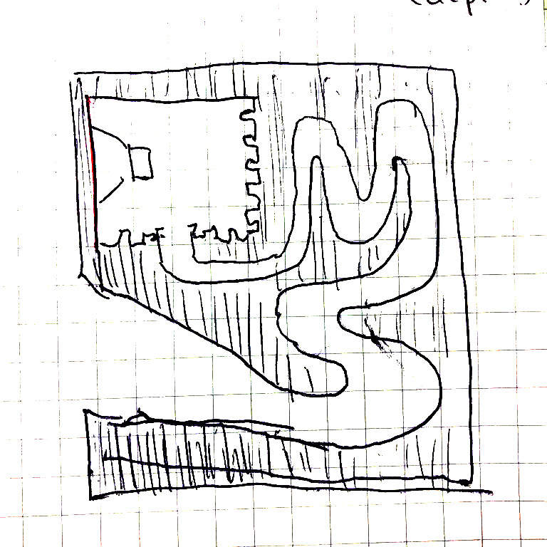
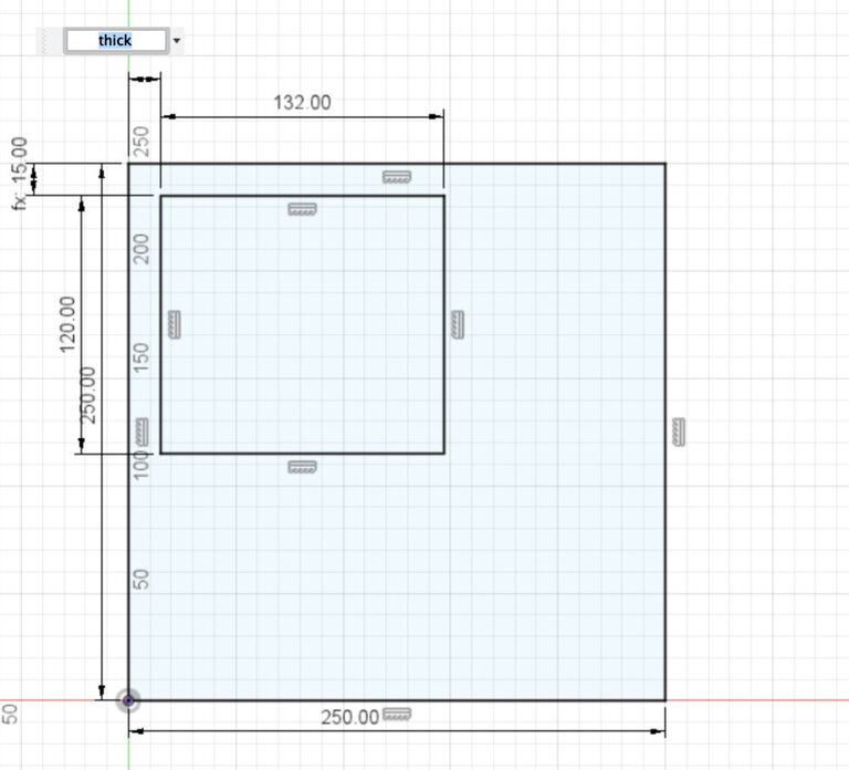
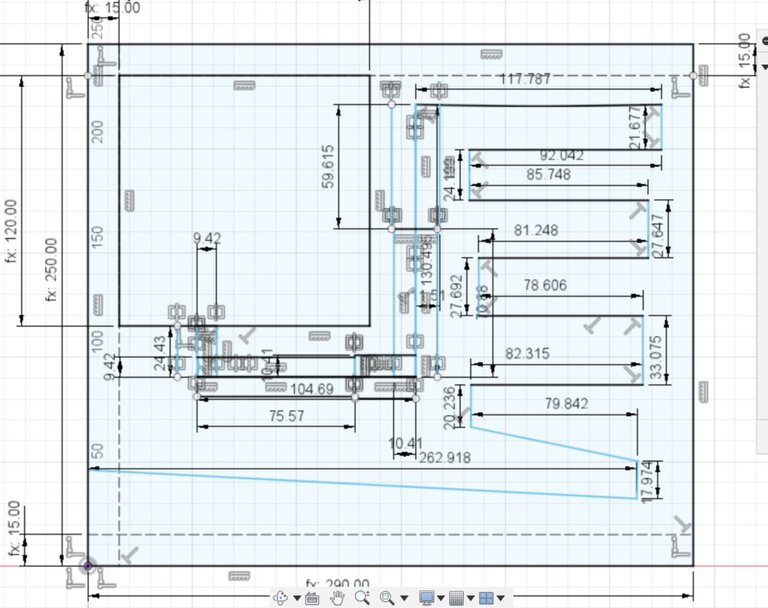
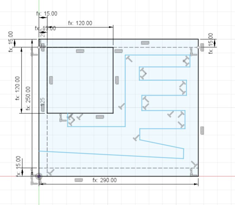
Firstly, I tried to design square shape from side view like above.
However, square type looks like desktop PC and I think that shape is not so cool and takes unnecessary space. . That's why I changed the design like this - longer hight and shorter duration.
Then I re-design the shape of horn. Finally, I got speaker with:
- 440mm (height)
- 108mm (width)
- 160mm (duration)
- 1100mm (length of backload horn)
.png_1000x_q85.jpg)
.png_1000x_q85.jpg)
_path_unconnected.png_1000x_q85.jpg)
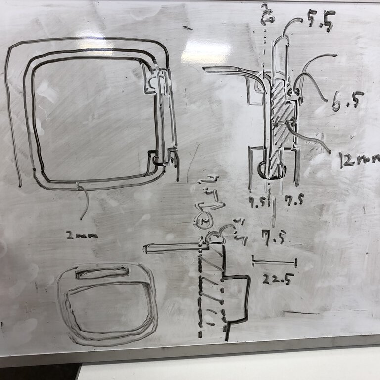
Joint with dog bone
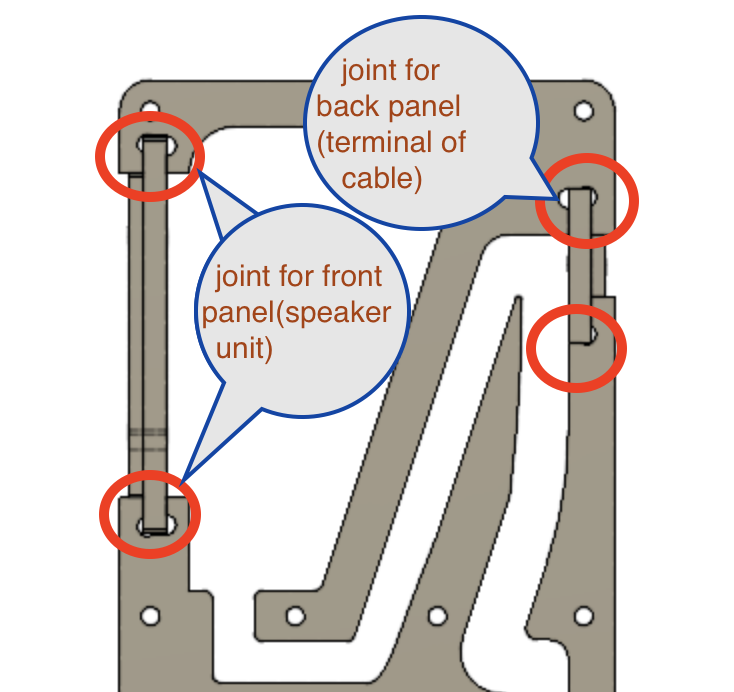
I designed the joint for front panel attaching speaker unit and the back panel for speaker cable terminal. It's good to make these panels by detachable joints as I want to change the size of speaker unit for experimental and maintenance reason.
As endmill is rounded shape and thicker than laser cutter or CNC for PCB milling machine, we need to open dog bone or similar shape when cutting inside of shapes.
_dogbone.png_1000x_q85.jpg)
_dogbone.png_1000x_q85.jpg)
As my speaker's surface is not so thick and some part only has 22.5mm, I designed the dog bone carefully so that I can keep thickness and strength of surface.
3D models
.png_1000x_q85.jpg)
When making complex sketch with bunch of parameters on Fusion360, the sketch or entire design tends to be heavy. Sometime it's freezed or brings unexpected error. Though I've been in trouble for too heavy sketch problem, I found a solution to resolve this finally.
Do not do every thing by single sketch. We can add or carve the model by extrude, join, cut using combined multiple sketch.
Plugin like "Shaper Utility" would be easily used for exporting svg file from sketch, surface of body and multiple bodies from the aspect of XY layer etc.
Finally, I built 3D model. I did cross section analysis and check every parts will be jointed consistently.
Test cut by laser cutter
.HEIC_1000x_q85.jpg)
I tested it by cutting 2/5 size (my original plan was using 15mm of MDF by laser cutter. I made the design by 3mm of tilia plywood and check joint tightness by 3 * 2mm of that .
Tilia plywood - Ref: wiki, maker's site
The length of design looks to be consistent. However, the depth and width of slit in dog bone joint is not enough tight. This is because of laser cutter's kerf under condition of Universal laser cutter in Kannai and the material of 3mm of plywood. I definitely need to do test cut by actual material that I mill in larger CNC.
Material (and re-design)
.HEIC_1000x_q85.jpg)
Originally, I planned to use 15mm of MDF. However, that material was sold out at CAINZ, home center near by Fablab Hamamatsu.
.HEIC_1000x_q85.jpg)
So, I needed to change the design of speaker. Some parts is redesigned by changing parameter of thickness while the other is not. It was because I used function like "mirror" or "circular pattern" and the pivot of the pattern was changed when I changed parameter.
It's good to set specific parameters that have strong possibility to be changed like thickness of material and kerf offset etc.
Be careful to the base of the design(construction plane, center or pivot) does not depends on changable element - otherwise the desgin will be broken unexpectedly.
Make data to import into CAM
As CAM tool at Fablab Hamamatsu - "Take Space" is good fit with Adobe Illustrator format, I made .ai files as following procedure.
- Make svg files from bodies (or sketches) in Fusion360 3D model (I used a plugin of "Shaper Utility".
- Open svg files on Adobe Illustrator and check and change paths on it (change border thickness and colors in fill and lines, then save the file with .ai prefix.
svg files
 outline
 side
side
 center
 front panel for FOSTEX P800K
 front panel for FOSTEX P650K
 back panel for speaker cable terminal
Mill
- Material : lauan plywood, 12mm thickness
- CNC router : ZN1325 at fablab Hamamatsu “Take-Space”
- Tool path maker : Vectric Cut2D Pro
Thanksfully, Fablab Hamamatsu accepted and allowed us to use Big CNC machine.
CAM Setting
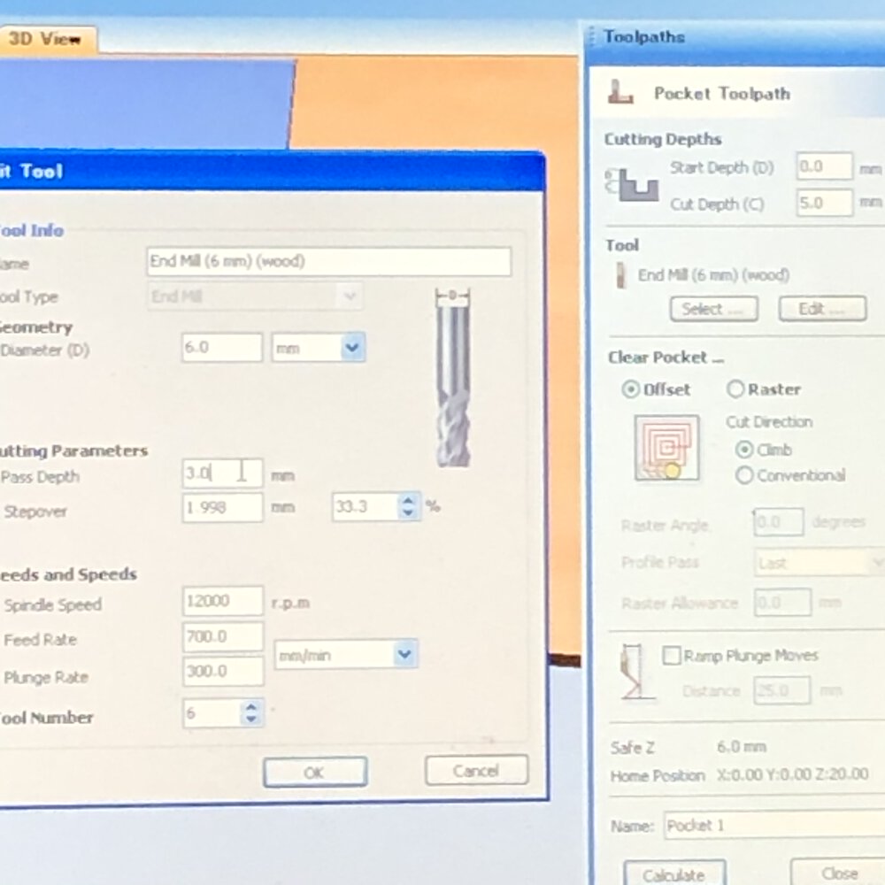
- Spindle speed = 12000 rpm
- Feed rate = 700.0 mm/min
- Plunge rate = 300.0 mm/min
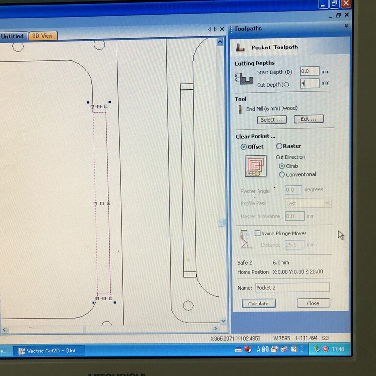
Making pocket, I used following settings.
- Start depth = 0.0mm
- Cut depth = 4mm
- Clear Pocket... = offset
- Cut Direction = Climb
Tool path
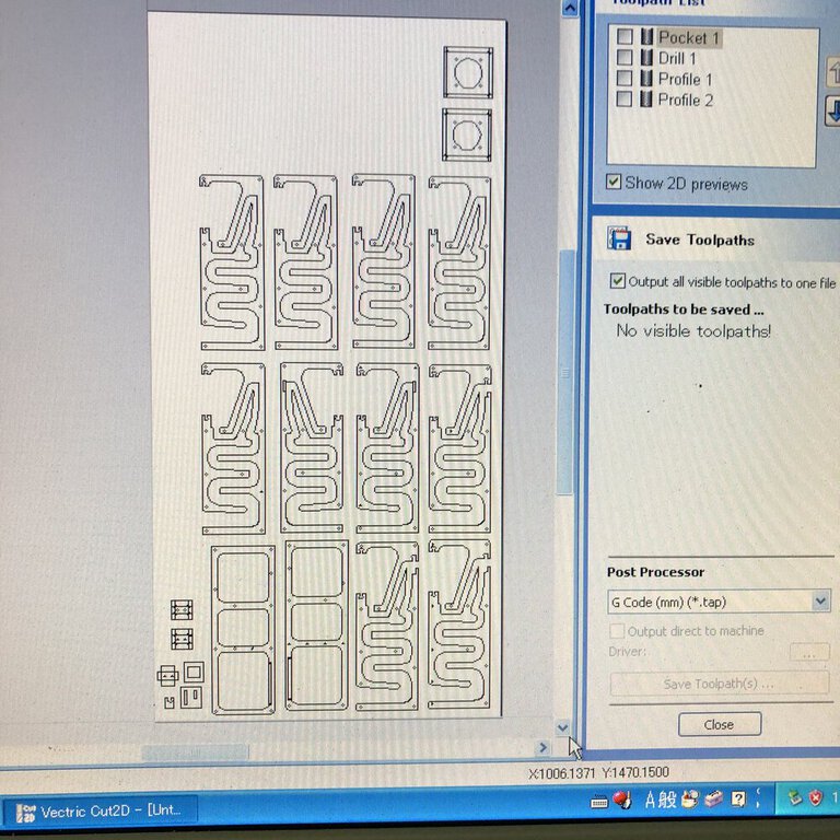
CAM toolpath is made by "Cut2D". I ordered and distributed the image to physical area of plywood board.
Cut2D supports move the path image to a specific position, edit path, making tab and export the data to .tap file (G Code) etc.
Preparation and Mill
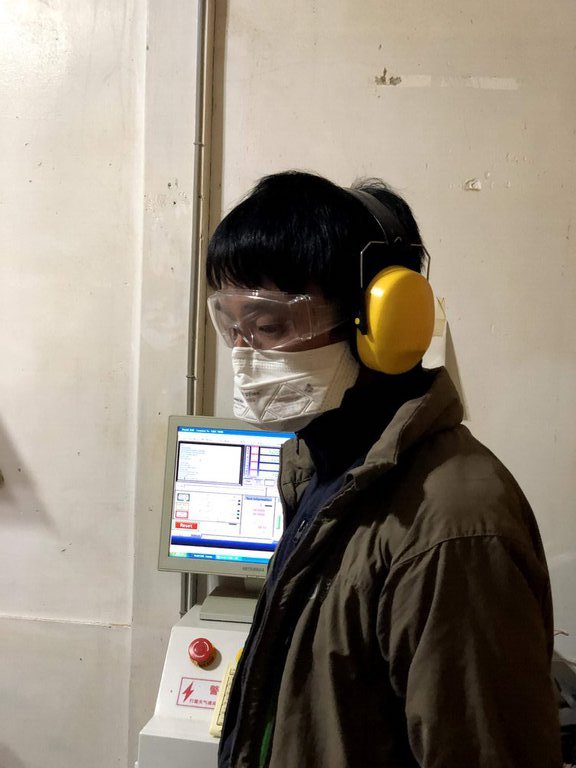
For safety, wearing
- cover glass
- headset
- (mask)
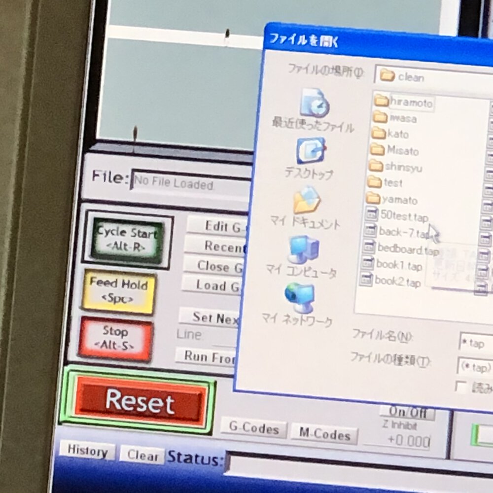
Import G Code(.tap file) at the button of "Load G Code"
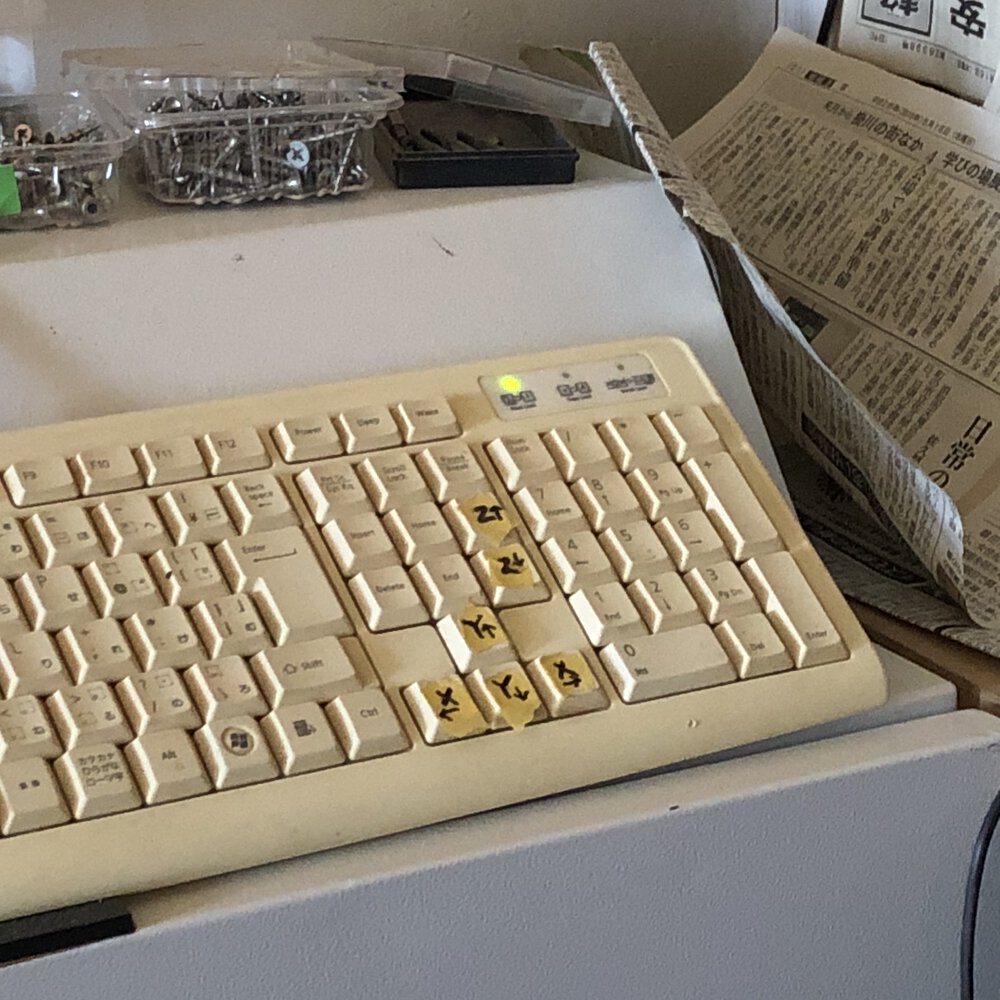
Start and reset buttons are both for CAM software and hardware button. Also, manipulating the XYZ axis are controlled by keyboard.
Step to setup the origin of tool is as follows
- Move the mill to the left - under corner of the material
- set origin (zero) of x axis and y axis
- check z axis hight by gently pushing the Down keys. The appropriate height of z axis is checked by news paper between mill and material board, then set origin(zero) for the tool.
setting “zero” (origin) for x-axis ( and then, y-axis also), after moving the mill to the corner of the wooden board.
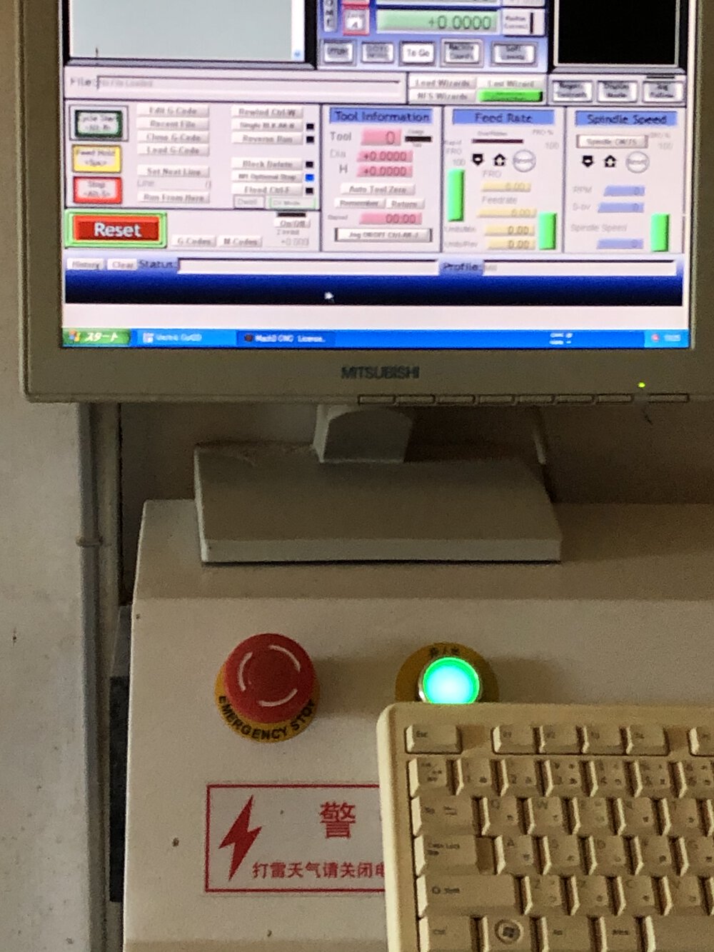
It's better to use software button for resetting the tool than using hardware button. Once pushing hardware button, we need to recover from the starting point of cutting.
Once stopping the CNC machine, be careful to restart it as the first step (to postioning z axis) will be reset on cancel the former milling.
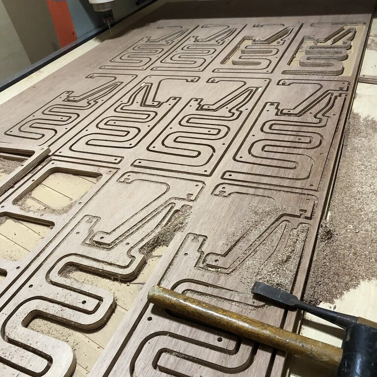
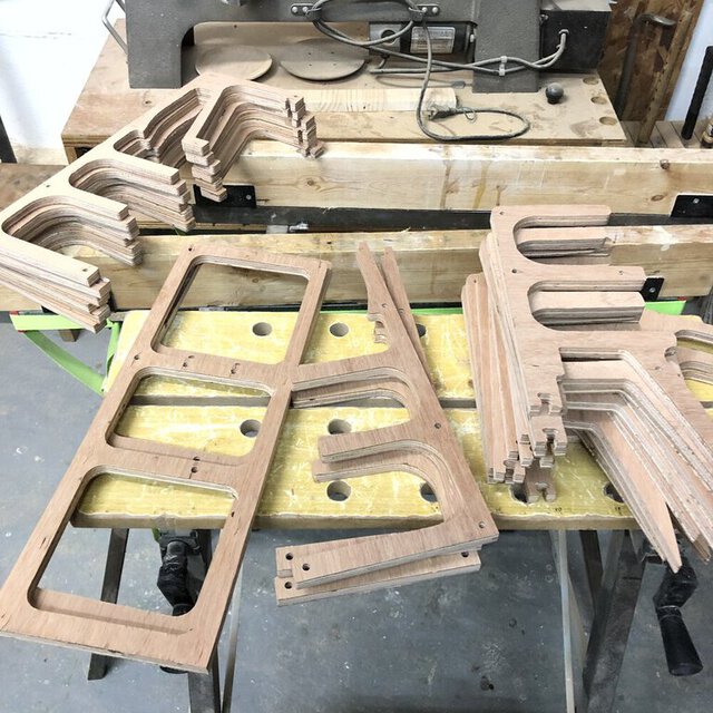
It took around 2.5 hours for cutting every parts of a speaker in total.
As we had time constraints for the remote location of Fablab Hamamatsu, I needed to change the plan from making stereo speaker into monoral speaker...

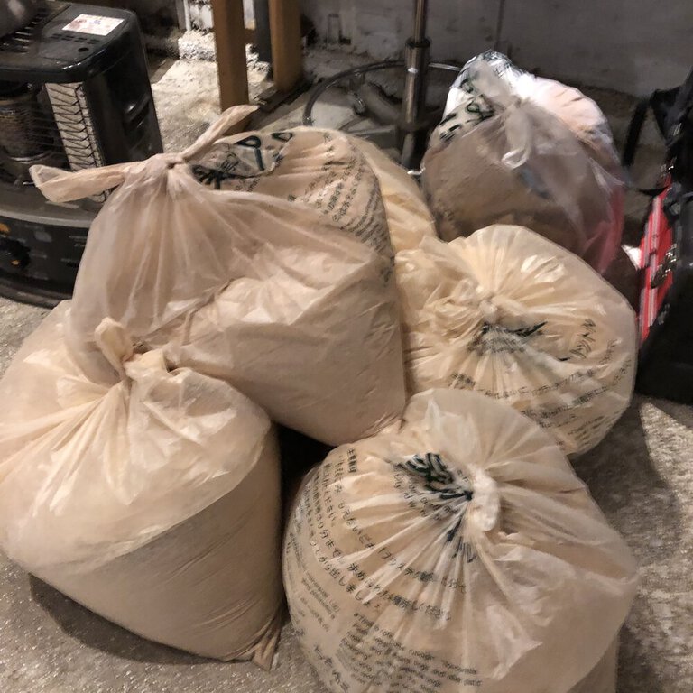
As I was the last user who had been using ZN1325 for FabAcademy for 4 days at Fablab Hamamatsu, I cleaned up the filter and cartridge covered by sawdust.
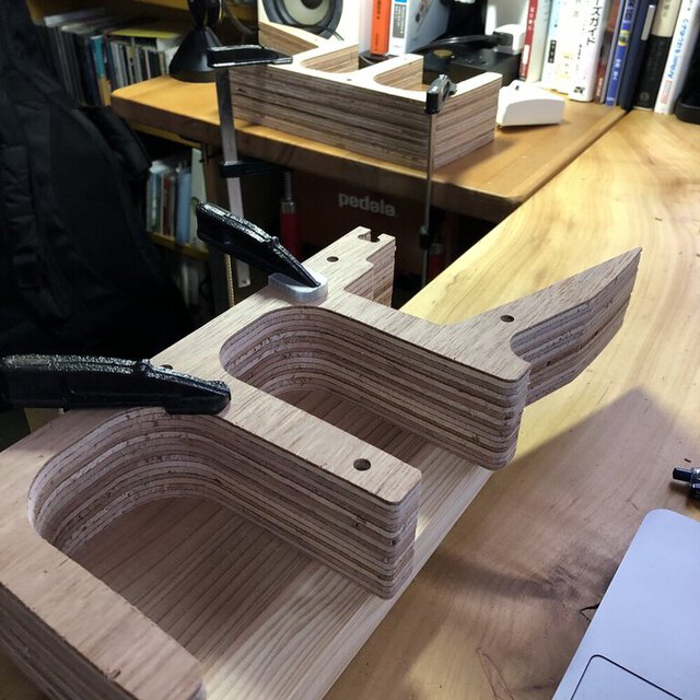
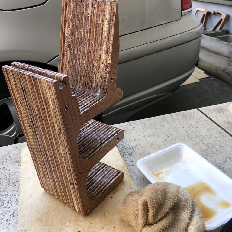
Assemble
Assemble took few days as I needed to leave that for a while as I partially used wood gleu and did oil finish.
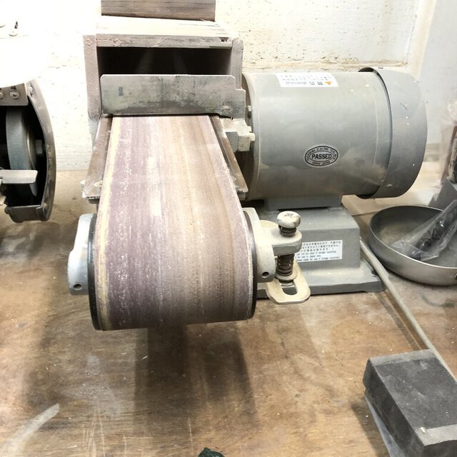
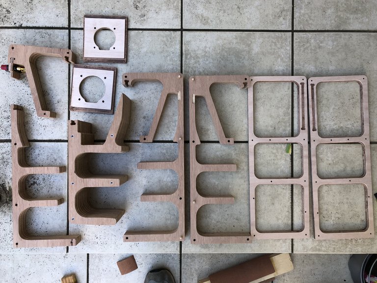
burring by belt sander at Take space
checked the quality of cutting - some drills are not penetrated through and the bottom thin board is pealed off in accident. I recut the material again as every part is not so big.

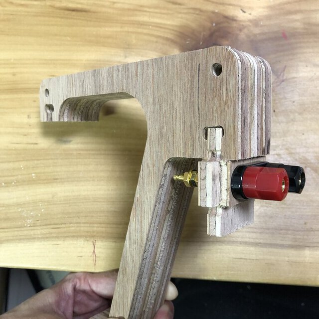
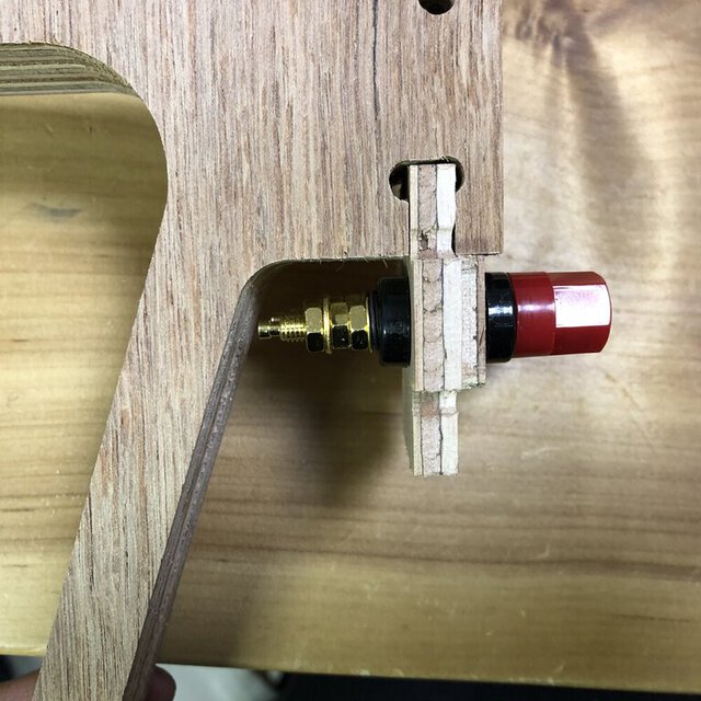
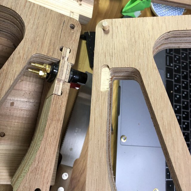
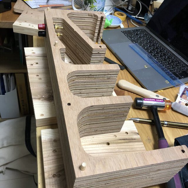
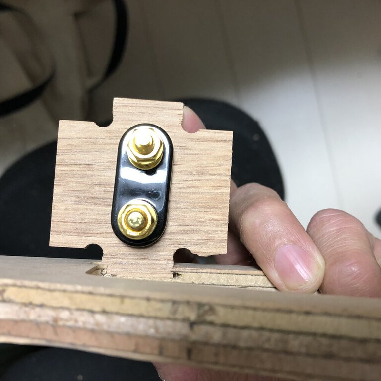
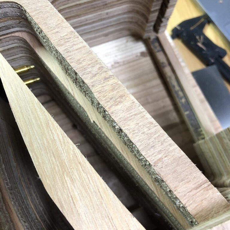
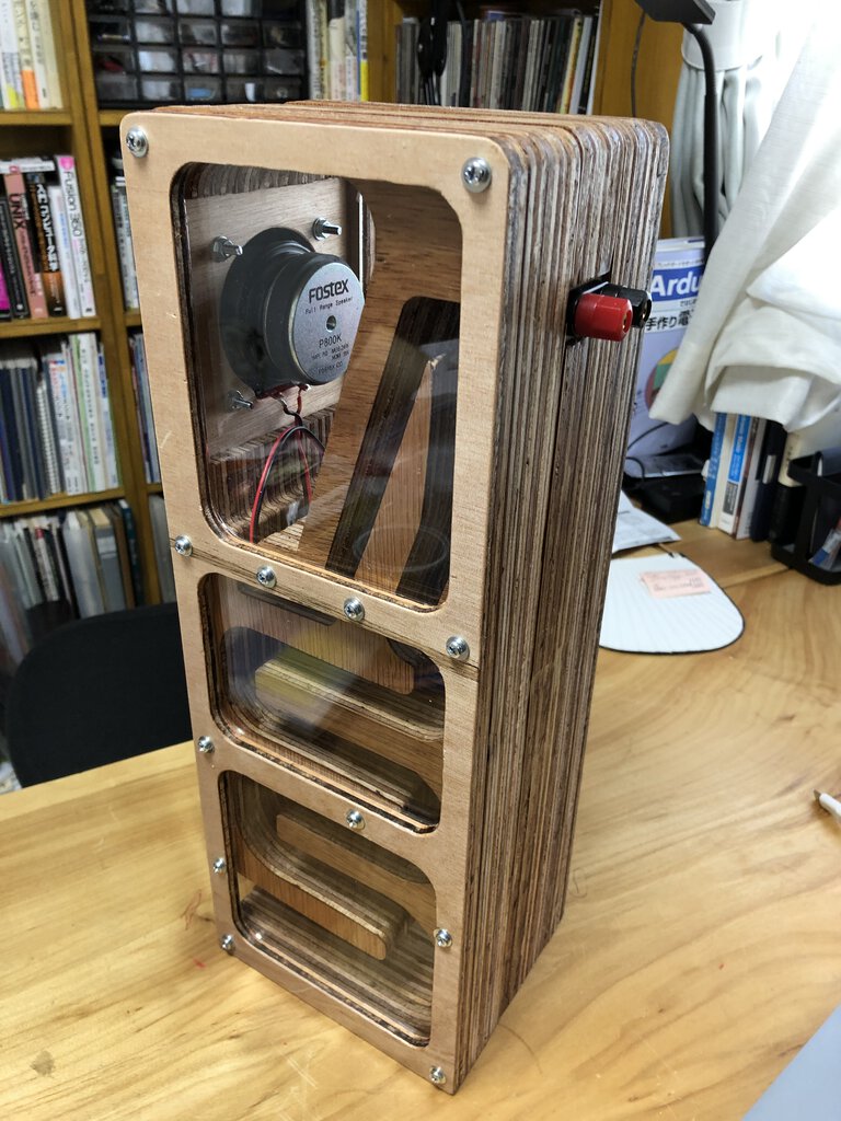
Joint for a panel of speaker cable terminal is tightly fixed.
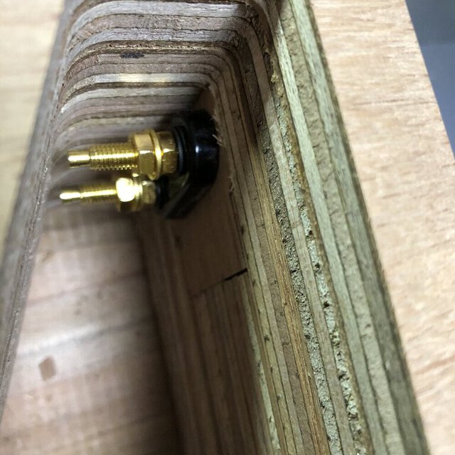
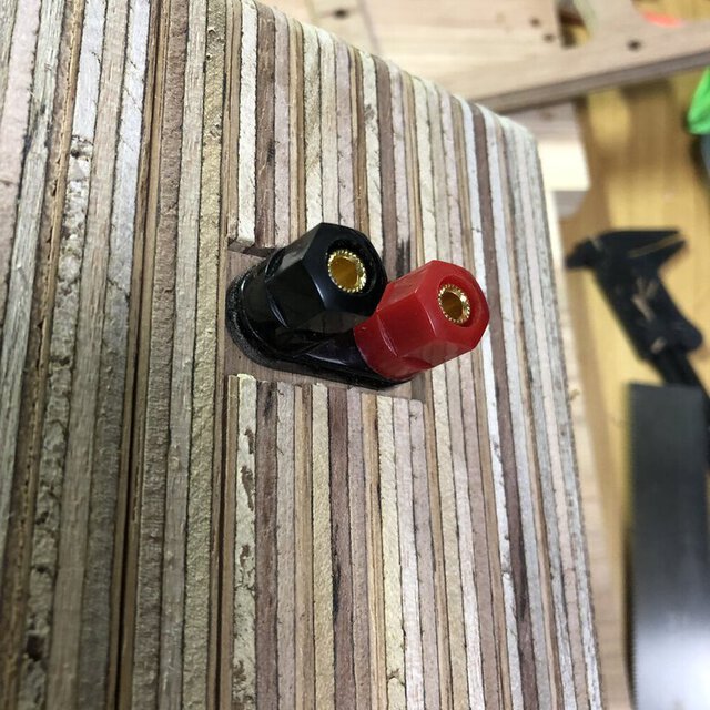
cable terminal is assembled.
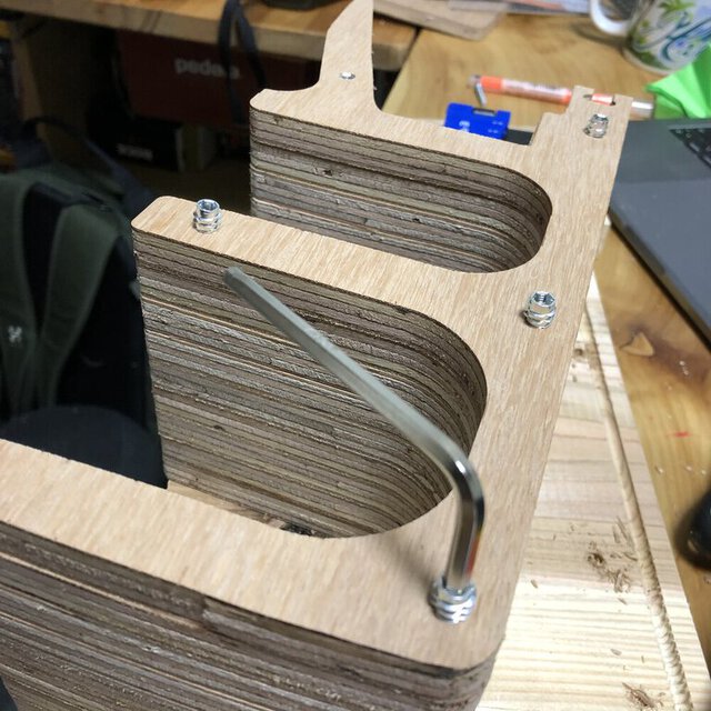
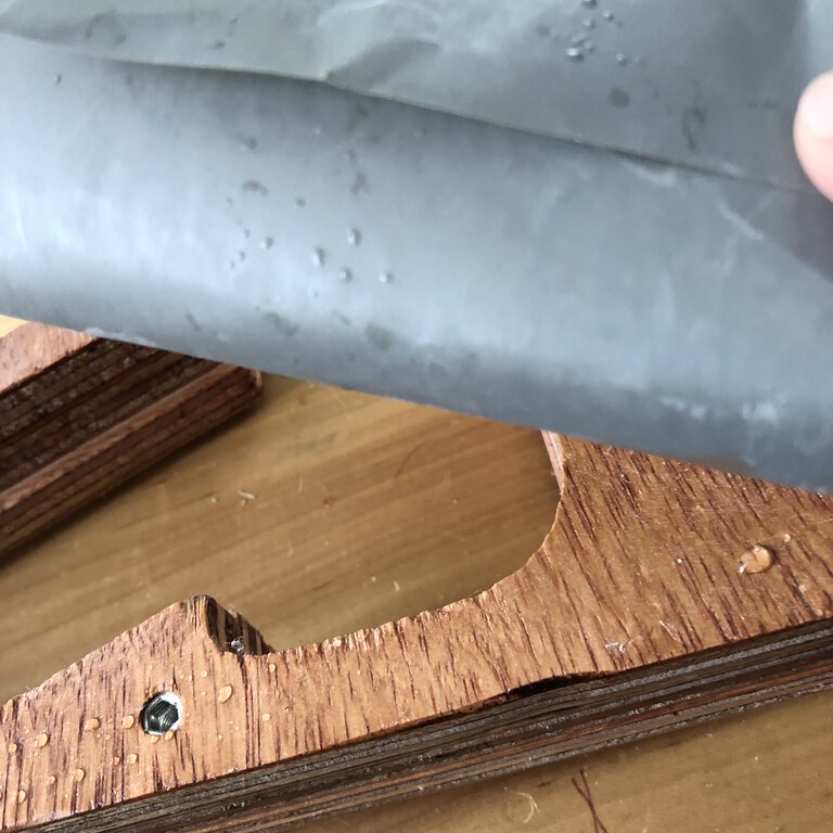
Using insertnut(鬼目ナット) for attaching tightly and detaching easily the cover for maintenance.
For fixing the position for attachment, I used a few dowel for each piece that I need to join.
This goes along with initial design of front panel slit.
This looks to be attached well, but I changed the design of this a little bit considering following problem and resolution.
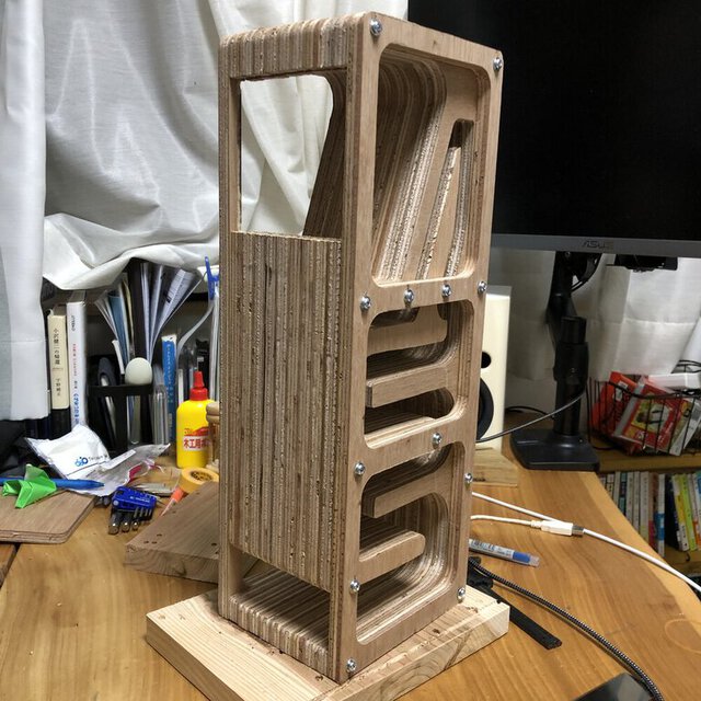
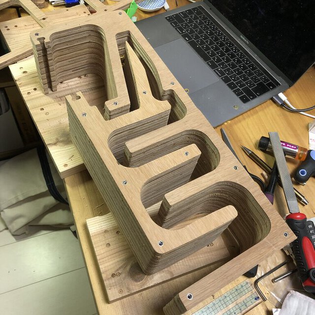
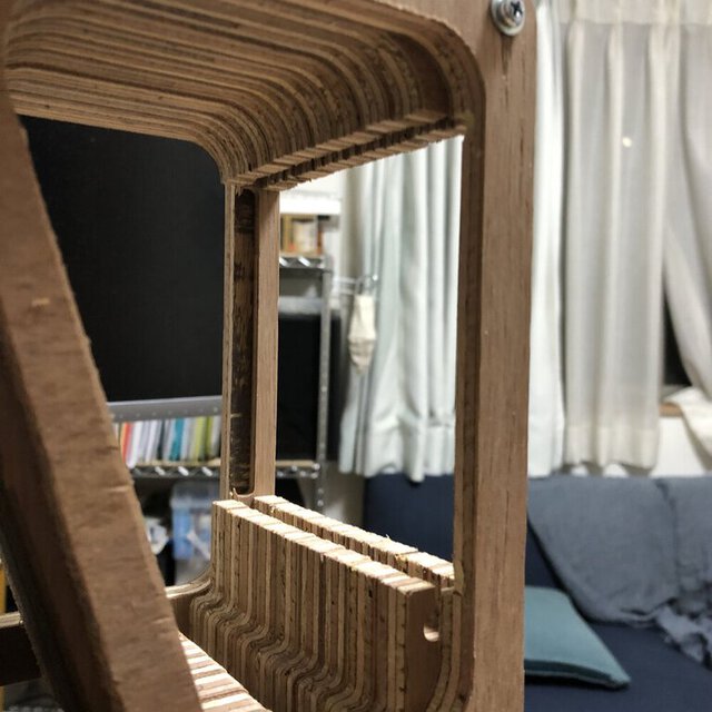
This is the first assembled example of backload horn speaker. Measurement looks to be fine, but I want to correct some points as follows.
Problems and first-aid
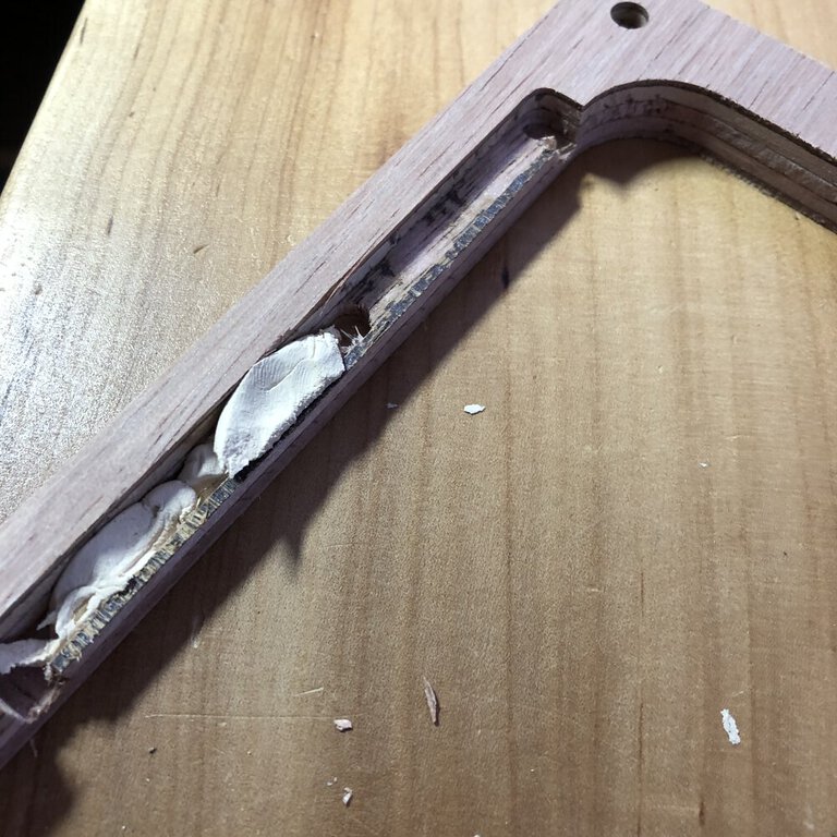
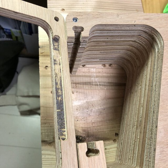
1. Failed to set the depth of pocket cut.
I wanted to do pocket cut by 5mm of depth firstly, but the mill goes to more than 5mm. That was due to incorrect value of setting on pocket cut in CAM.
Luckily it was not penetrated. So, I put wood pate to the part of too deep hole.
Afterward, I re-design the outline panel with more tight joint for front panel and hold for acrylic side window.

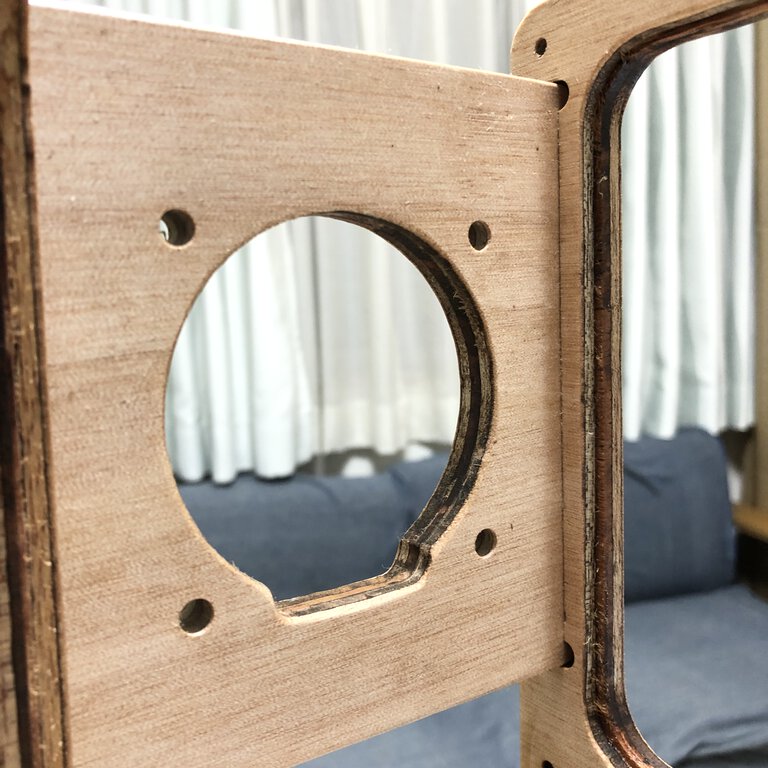
2. Unpenetrated profile and drill
As the material board it self and the sacrifice board seem to be slightly warped, the upper part of material was not fully penetrated on drill and profile cut.
Also, I setupu drill cut depth as 12.5mm against the 12mm thickness of plywood - 12.5mm looks not to be enough depth of drill cut.
For recovery,I cut off the last 1mm of unpenetrated part by cutter. For drill, I made a penetrated hole by electric drill.
3. Mismatched joint
The depth of pocket for back panel was 4mm depth but the joint length to be inserted to the pocket was 7mm.
I cut-off the joint by saw and shrink the length into 4mm.
4. Insufficient tags for narrow part
When cutting narrow part, the material was not enough fixed that the cutline became unstable. It seemed to be rare case, but as this picture, some part was not cut as designed.
Though the inside of speaker does not appeal their shape, I needed to smoothen by file as long as I can.
Rebuild
Actually, I forgot to pocket cut for attaching acrylic panel to the outline side panel. I discussed with my instructor, Tamiya-san, about how to recover this.
I decided to redesign the outline panel and make 2mm range of pocket offset to the window and make the joint parts a little thicker that can hold the acrylic panel with the offset.
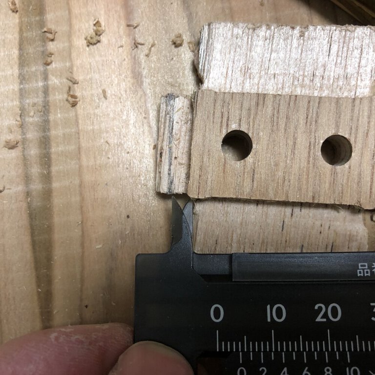
This time, I successfully cut the pocket for slit that combines with front panel. I designed the depth of pocket as 7mm and the joint parts length as 6.58mm.
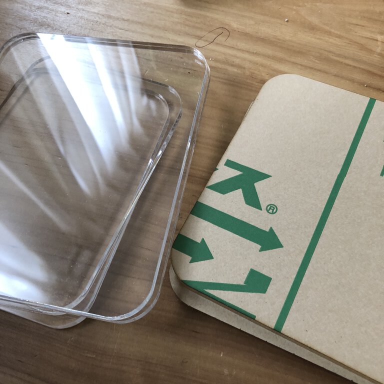
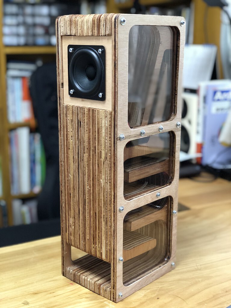
For the transparent panel on the side outline, I cut acrylic panel with 5mm thickness. The measurement of acrylic panel is just the same as the windows in side outline. The kerf of milling machine and laser cutter solves would solve the tight insertion.
Finally, I got my original backload horn speaker!
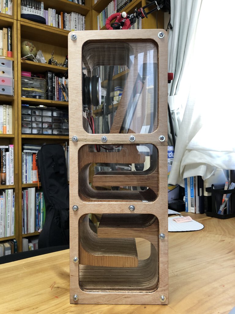
Sound check
To be updated - I need to prepare monoral amp.
Materials
| parts | amount | price | memo |
|---|---|---|---|
| Lauan plywood, 12mm thickness, 910mm x 1810mm | 1 | 1850 yen | CAINZ Hamamatsu Yuto |
| Acrilic (transparent), 5mm thickness, 300mm x 450mm | 1 | 1000 yen | Stock at Fablab Kannai |
| Speaker Unit(FOSTEX P800K) | 1 | 1236 yen | Amazon.co.jp |
| Speaker cable, 0.3mm^2 x 2C | around 30cm | 300 yen(5m) | 秋月電子(akizukidenshi) |
| Speaker terminal | 1 | 600 yen (per 1 part) | (2 parts 1200yen) Amazon.co.jp |
| Insert nut(鬼目ナット), M4 x 10mm | 28 | 890 yen | (6 pieces * 5 pack)CAINZ Hamamatsu Yuto |
| Pan head screw(鍋ネジ), M4 x 25mm | 28 | 255 yen | (10 pieces x 3 pack)CAINZ Hamamatsu Yuto |
| dowel(ダボ), 6mm | 8 | 118 yen | (10 pieces) D2 (ケイヨーデイツー) |
| glue for wood | N/A | N/A | Stock at Fablab Kannnai |
| Sand paper(#120, #240, #2400) | 5 | 150 yen | CAINZ Hamamatsu Yuto |
| Oil (Osmo color, clear) | N/A | N/A | Stock at home |
| Solder | N/A | N/A | Stock at home |
| Summary | 6399 yen |
Files
- 2D/3D design : link to Autodesk 360, f3d
- SVG files : w07_speaker_svg.zip
Lessons Learned
- Large CNC machine is super useful to make big or complex things. It was very good experience for me to make my first speaker by CNC machine.
- Knowing about various way of cutting supported by CNC router(outer/inner profile cut, pocket or drill etc.) will bring imagination about more intersting design.
- Fablab Hamamatsu ("Take Space") is hot spot for making almost everything. Massive tools including carpentry work and relaxed space allowed us to proceed work well.
- It took very long time for me to design, test and re-design etc. That's my issue to be improved. Need to grab the firstest way to proceed design quickly and accomplish assignment criteria firstly.
- It's key for making stable and traceable design to utilize function of CAD tool effectively like parametric modelling, mirror or tangent arc etc. As these function are quite strong but has trade-off to constraints and system resource, it'd good to pick the appropriate area to be adopted with imagination like "if this is changed in the future, what happens?". In many cases, mirror pivot or center of circular pattern should not be moved even though related parameter is changed. Be careful not to make heavy sketch.
References
- Fablab Hamamatsu - ”Take Space"
- FOSTEX P800K
- youtube video by Super Techsan who made a backload horn speaker by tip saw and router.
- BH型スピーカーを設計しよう ~その2 (空気室編)~(Japanese: Let's design BH type speaker 2: Air chamber)
- Youtube video by Mr. ICHIKEN
- Eduardo Sogovia in FabAcademy 2019 made a speaker and amplification device as an assignment of output device