Assignment
Week3: Computer Controlled Cutting
Assignment
- Group Assignment
- characterize your lasercutter's focus, power, speed, rate, kerf, and joint clearance
- document your work (individually or in group)
- Individual Assignment
- Design, lasercut, and document a parametric press-fit construction kit, which can be
assembled in multiple ways. Account for the lasercutter kerf.
- cut something on the vinylcutter
- characterize your lasercutter's focus, power, speed, rate, kerf, and joint clearance
- document your work (individually or in group)
- Design, lasercut, and document a parametric press-fit construction kit, which can be assembled in multiple ways. Account for the lasercutter kerf.
- cut something on the vinylcutter
My Work
I've learned about laser cutter and vinyl cutter at Fablab Kannai from my instructor Tamiya-san.
Group Assignment
Link to group assignment page at Kannai lab
Concept of Construction Kit
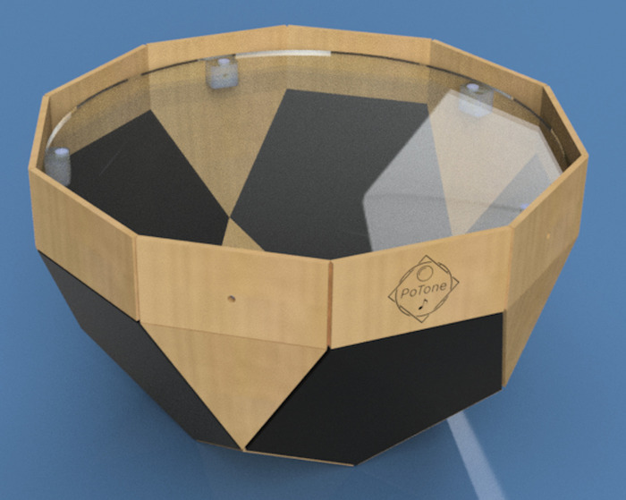
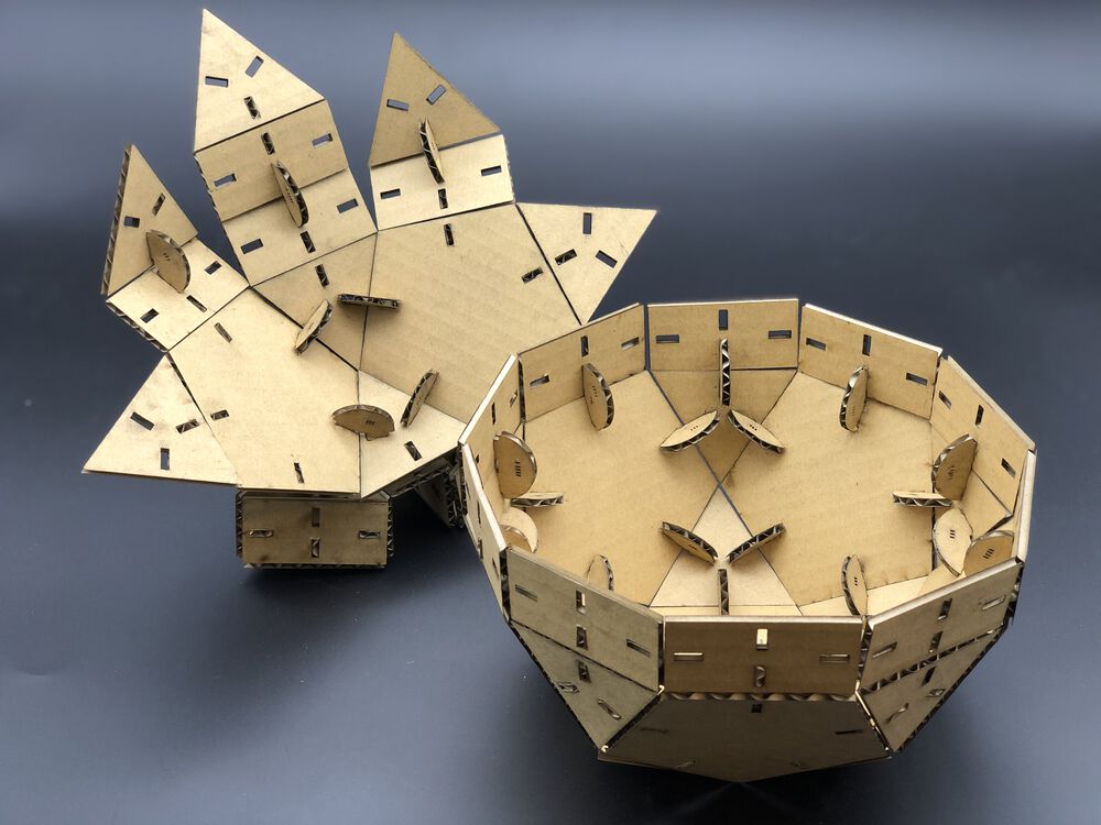
As the shape of my initial design of final project (a.k.a. "Pot") is polyhedron(凸多面体) - "Gyroelongated pentagonal rotunda" comprised by regular polygons, I came up with the idea of a constructional kit that can make polyhedron. The surface of shape would be polygons like regular triangle, pentagon and rectangle. Joint needs to have a function that can attache the surfaces in multiple angles.
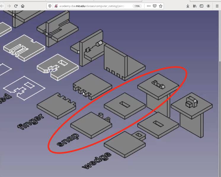
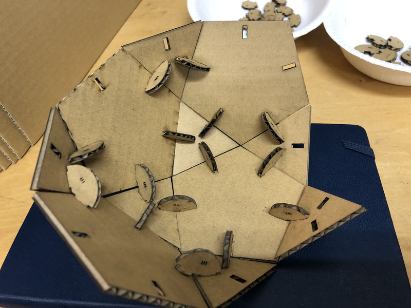
For attaching the surfaces, I decided to use the "snap" joint.
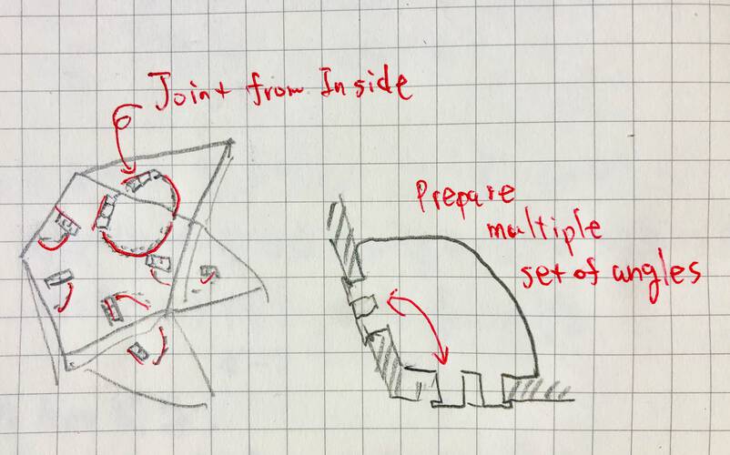
Joint from inside of polyhedron (not push out the edges as long as possible).
Multiple set of joint with different angles would allow players to make various constructional object!
Design of Construction Kit
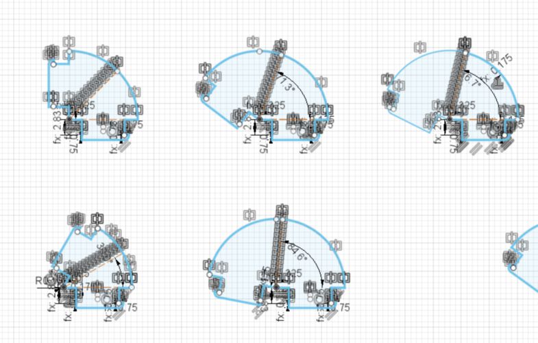
Measure the angles in 3D Model
For attaching the surface of polyhedron, I measured the model that I made in week02.
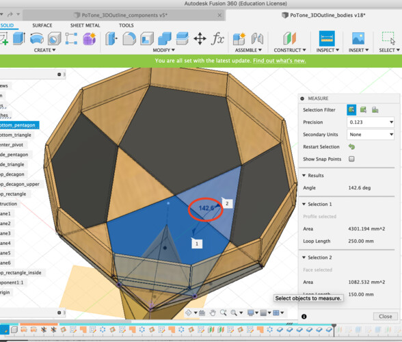
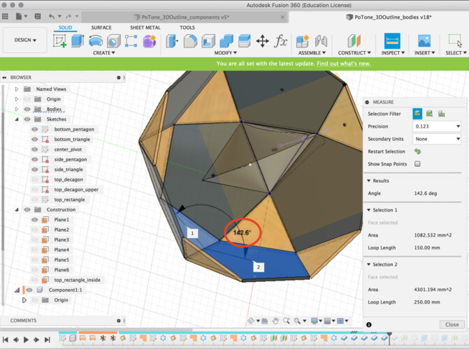
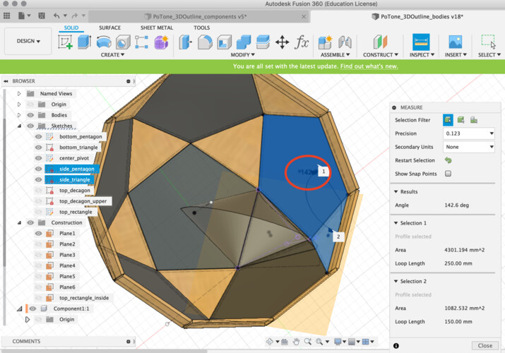
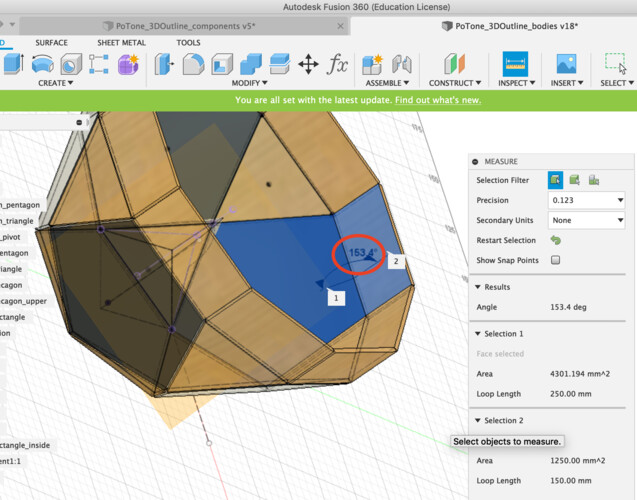
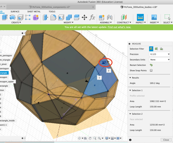
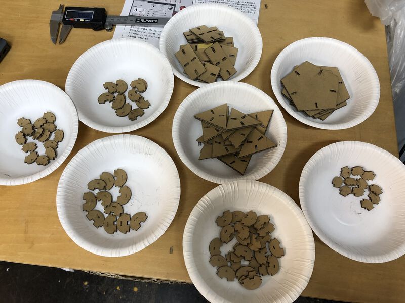
For making "Pot", I need at least following joint:
- 25 pieces of 142.6 deg. joint (pentagon and triangle)
- 5 pieces of 153.4 deg. joint (pentagon and top rectangle)
- 5 pieces of 169.2 deg. joint (triangle and top rectangle)
- 10 pieces of 144 deg. joint (inner angle of regular decagon)
And more for various constructions!
Sketch the Kit
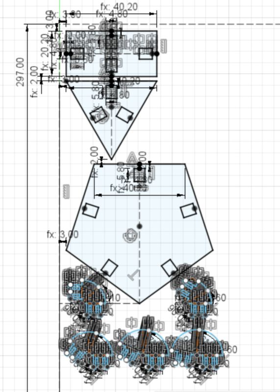
■ Sketch the shape of polygons with parametric modelI sketched the 2D model of construction kit using Fusion 360 for parametric modeling of construction kit.
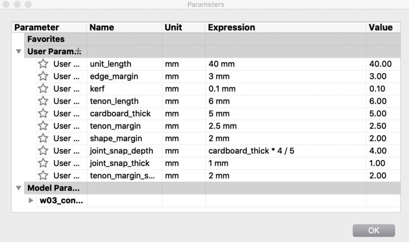
At first, I applied parameters in so many places in sketch of Fusion360. However, I realized that it's not necessarily good way to set everything as a parameter. It's because 1) too many constraint increase complexity of constraints dependency. and 2) 1) causes error and unexpected behavior in model. 3) CorelDRAW, a graphic software that are used for sending cutting data to Universal Lasercutter at Fablab Kannai, has strong power that specifies the location or color settings of shapes to cut.
That's why I designed a vector lines separately for each part, then converted it into vector image in svg file. In CorrelDRAW, I checked the space and alignment for each part and finalize the cutting data.
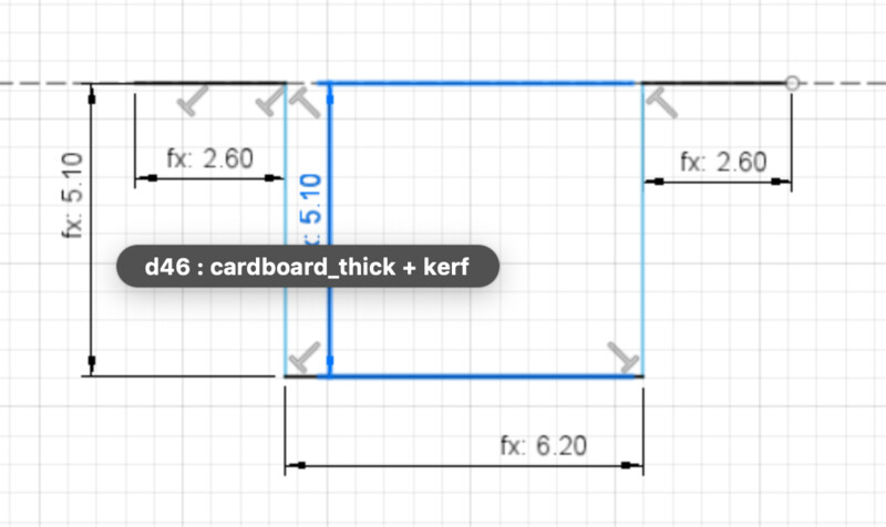
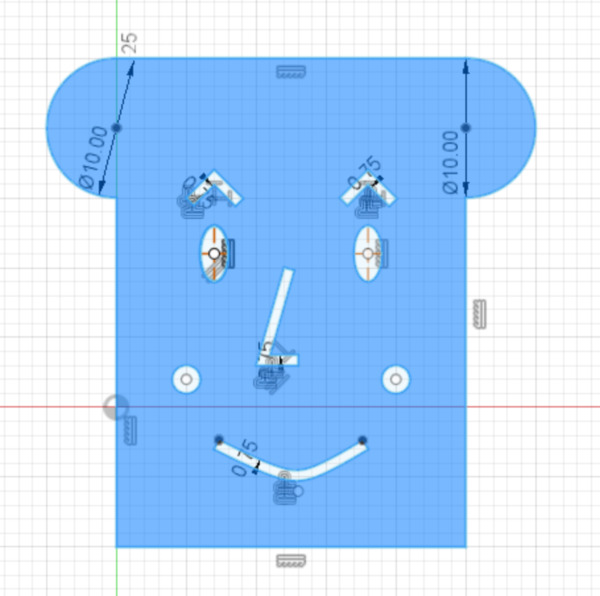
1. sketch the joint considering cardboard thick(2.83mm) and kerf(3.5mm)
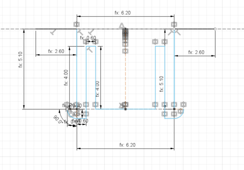
2. mirror the snap to the other side. (Actually, this the final idea of joint is not symmetry for easily attaching the joint)
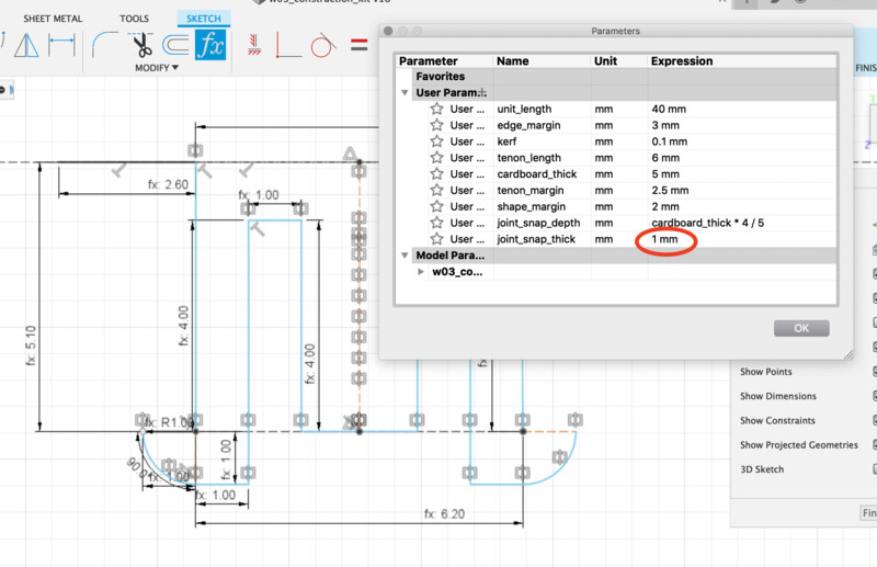
3. set the joint snap ledge to 1mm.
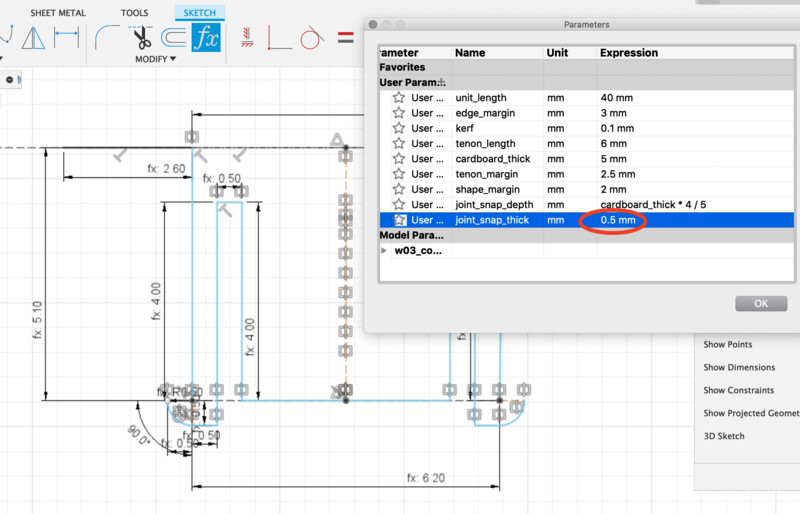
4. set the joint snap thick to 0.5mm (Actually, this was too shallow to fixing the cardboard surface)
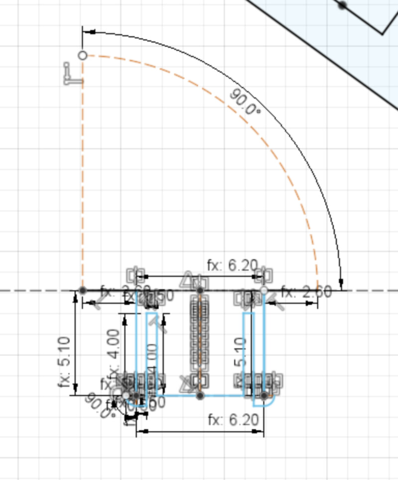
5. Draw center point arc as the construction line of angle.
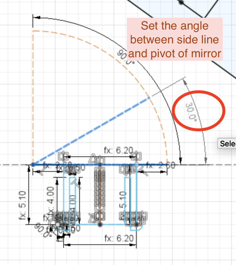
6. Draw construction line and set the angle for pivot of mirror
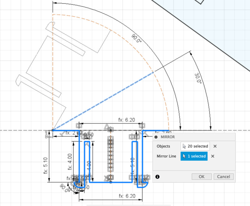
7. Mirror the sketch profiles to the other side.
You can add the kerf as a parameter to every dimension of the shape for cutting. However, designing complex shapes like joint as above in that way is too difficult and too much constraint conflicts in CAD tool.
Instead, I used "Offset" function in the sketch of Fusion360 for spacint the line as the offset to desirable cutting edge.
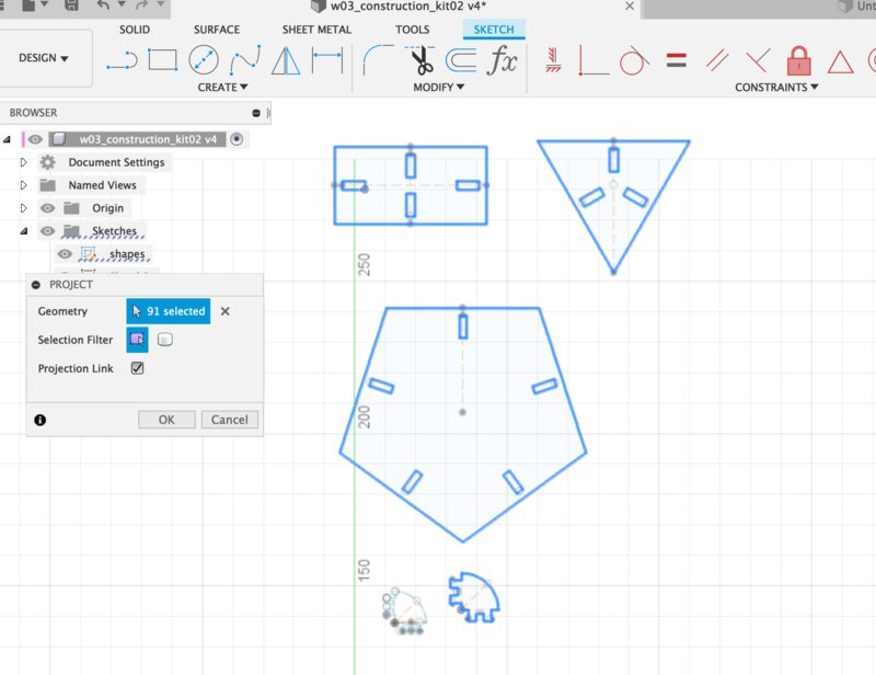
1. At the new sketch, create the projection line from original sketch (that is not reflected the kerf calculation).
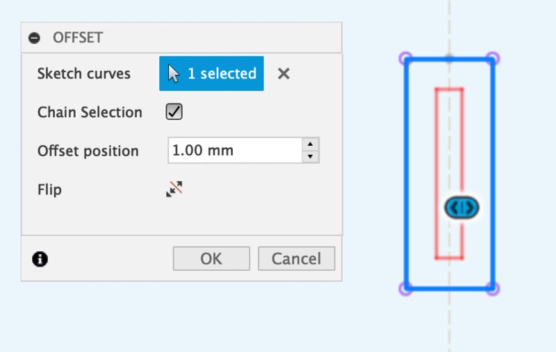
2. In "offset" dialog, check the direction. If you want to cut outside of the shape, offset is external line. If inside, offset is internal line.
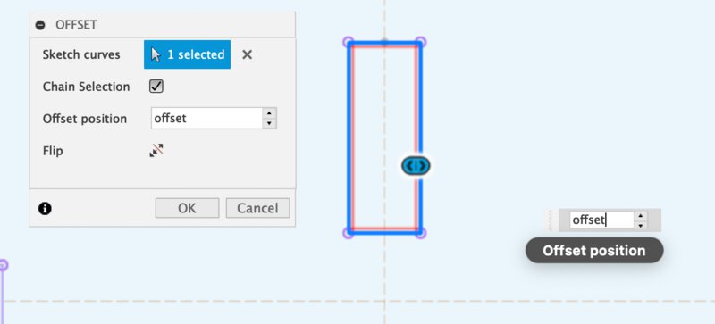
3. Reflect the offset line to the sketch.
Offset value is "a half of kerf". As I determined that the kerf for cutting cardboard in 3 mm thick is 0.35mm, the offset is set into 0.175mm
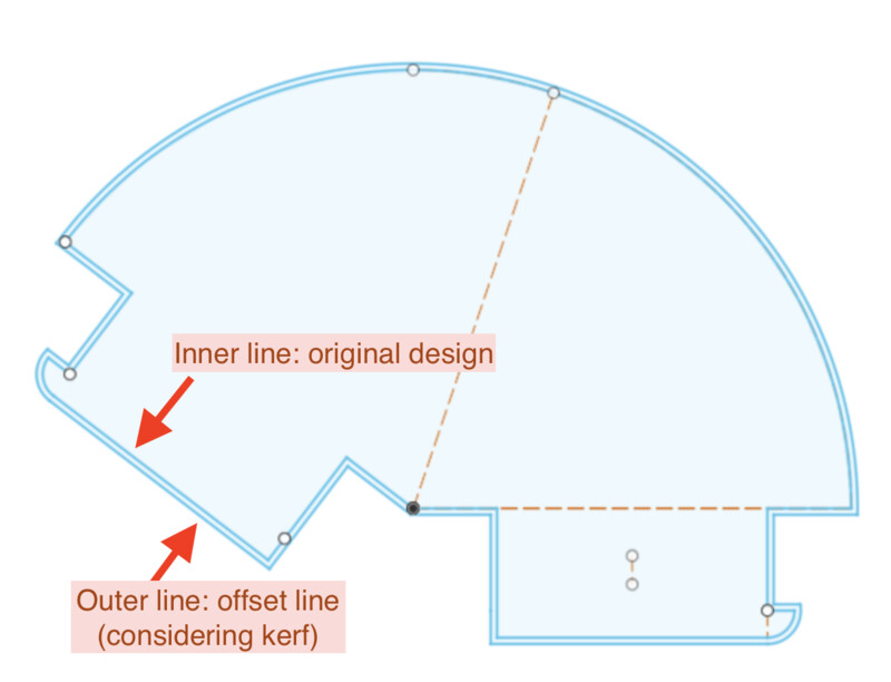
It's helpful to use offset function especially in considering kerf in complex design.
Generate the SVG file from Fusion360
There are several way to store the svg file to be accepted by cnc machines. For example, exporting dxf from Fusion360 and change it into svg from tools like Inkscape.
This time, I tried to use "Shaper Utility", a plugin of Fusion360. It's very straight forward to export svg file directly from 3D model using shaper utility.
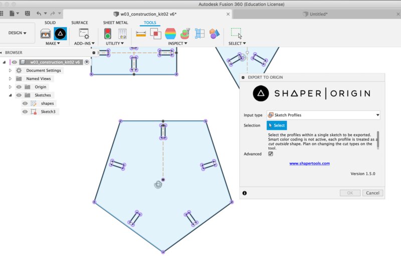
1. Tool > Shaper Utility and select "sketch profiles"
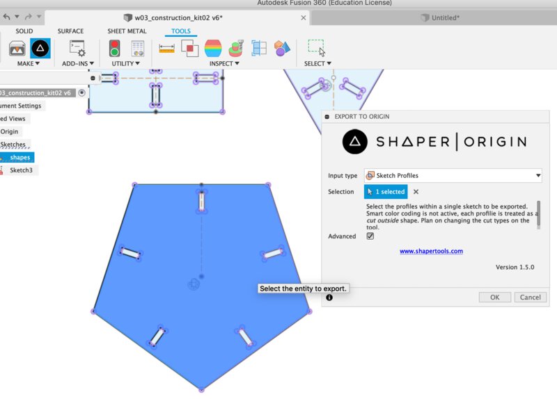
2. select the sketch profiles that you want to convert to SVG.
Occasionally, you cannot select the sketch profile especially in case of offset line. In that case, you can make body by extruding the offset sketch, check "single solid body" in 1., then you can get offset line of sketch.
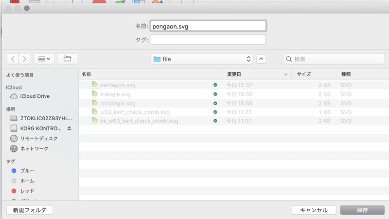
3. save the SVG file directly to local storage.
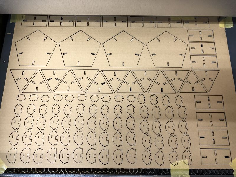
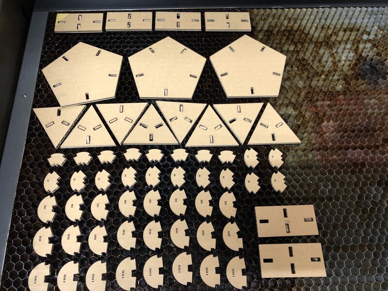
Laser Cut Construction kit
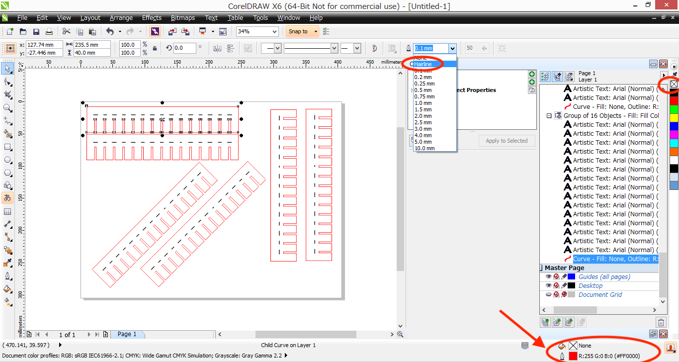
Using CorelDRAW that is installed for client laptop of Universal laser cutter, I consolidated the position, alignment and spaces of shapes.
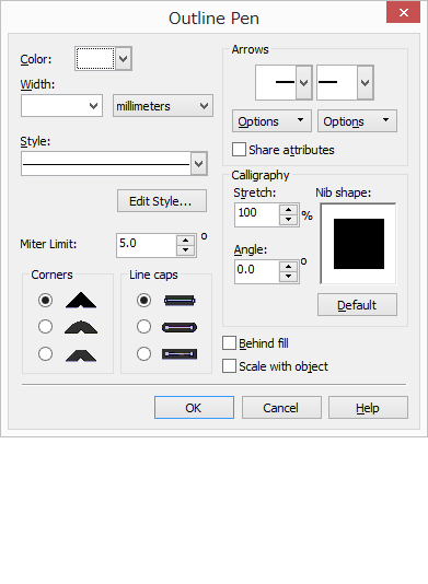
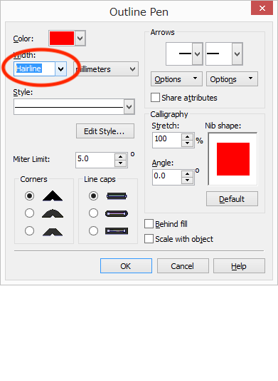
make the line for cut to ”hairline” and clear the color filled inside of the shape.
Following what I found on characterizing the laser cutter (especially in cutting a cardboard in 3mm thick), I set the parameter of Universal VLS Desktop VLS2.30 as follows.
| Color | Mode | Output | Speed | DPI |
| Black | Raster | 80% | 100% | 500 |
| Red | Vector | 50% | 4% | 250 |
I did cut several times before mass producing.
Round 1. shape of joint was weak. I changed the design of joint from "deep slit for snap for both side into "no slit and for 1 side".
Round 2. The length of rectangle was not valid because the area of sketch that I selected on "shaper utility" was incorrect.
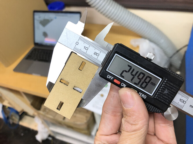
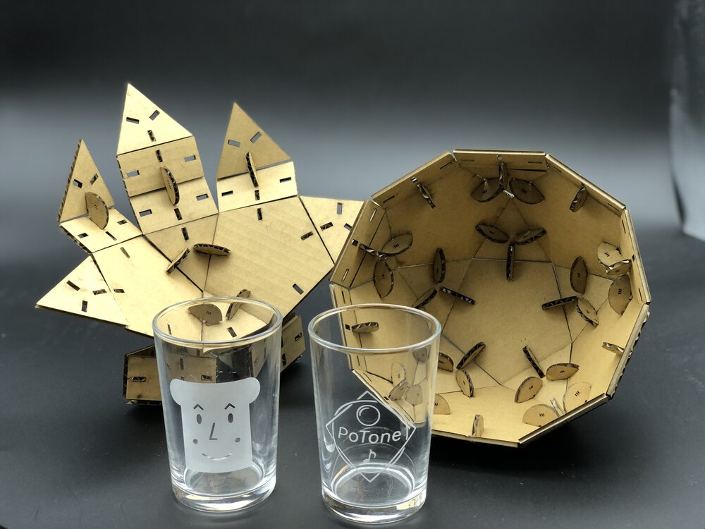
Finally, I could measure 24.98mm in physical material cutout from design of 25.00mm!
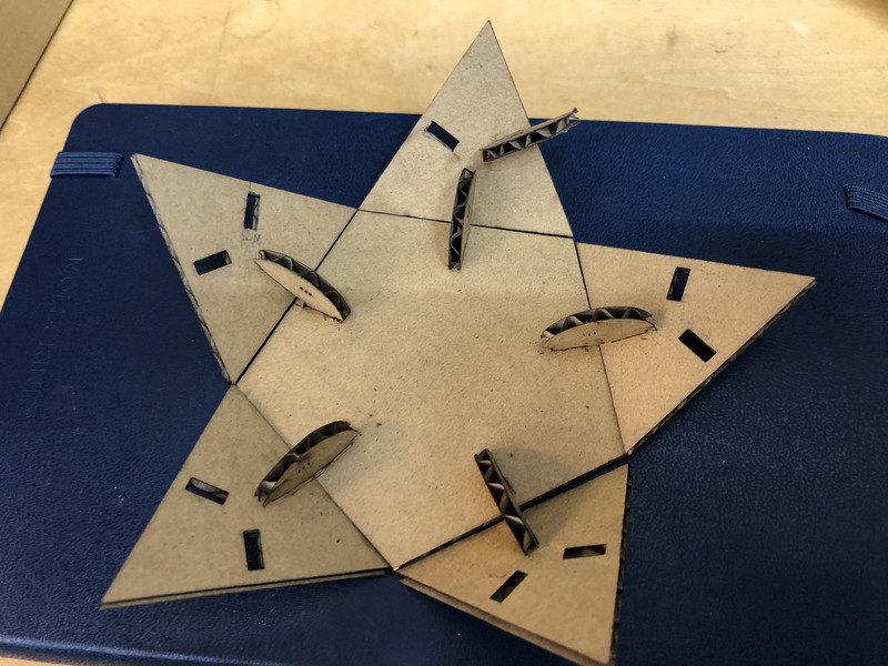
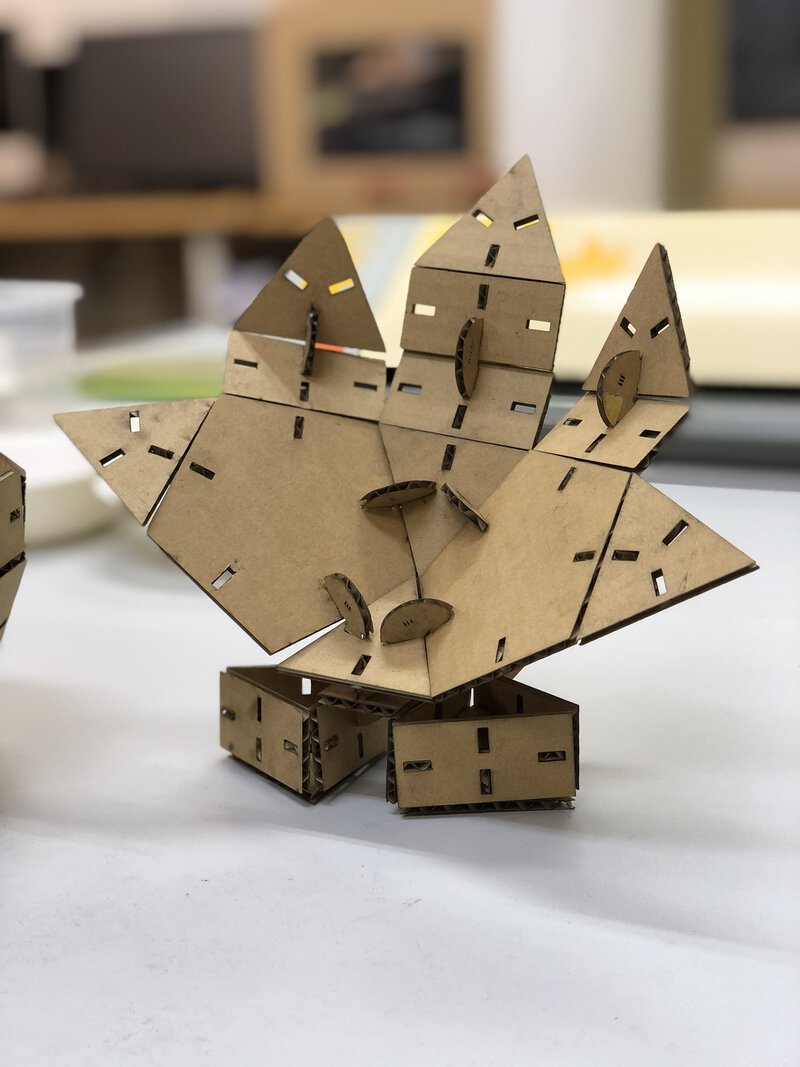
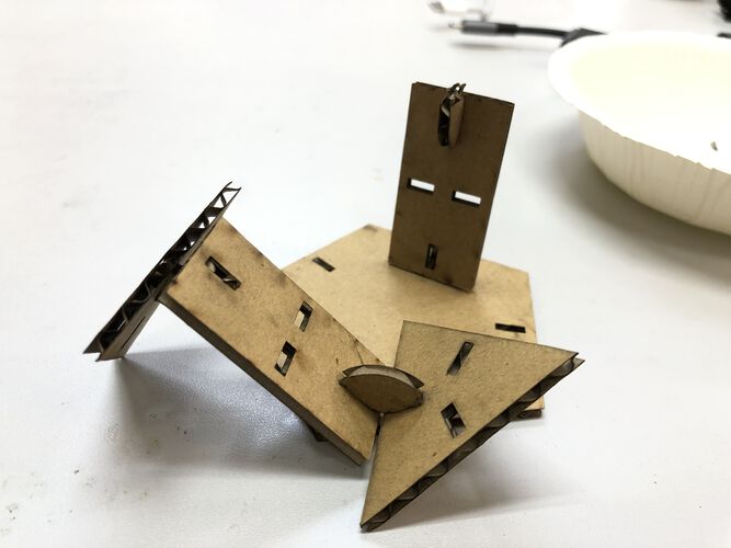
Assembling in a different way. Multiple angles of joint supports various expression.
This is "Hand"...?
Vinyl Cut and Sand Blast
I tried to cut data both from raster image and vector image.
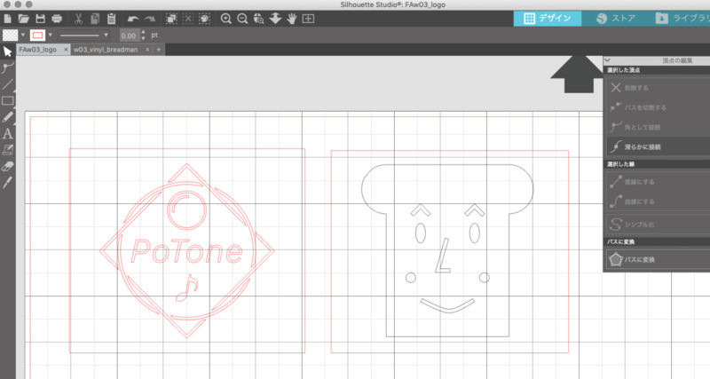
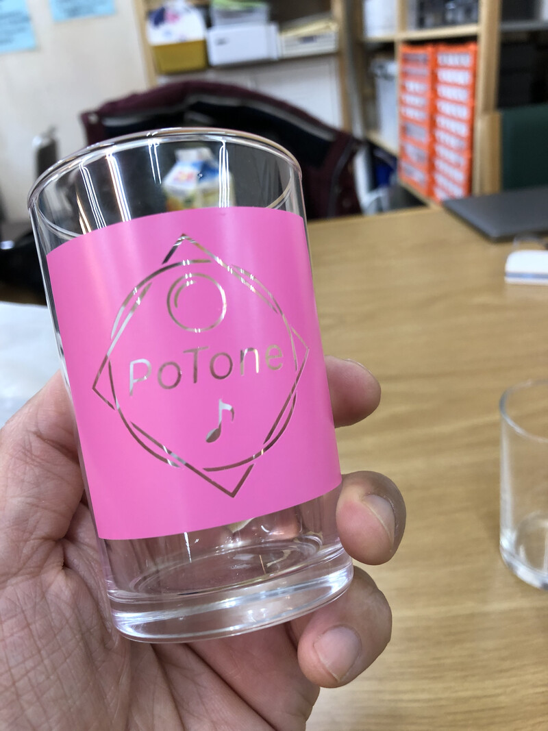
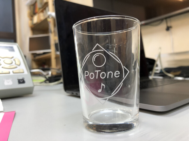
Raster Image: "PotTone" logo
I traced a png data that I created by GIMP in week1 assignment
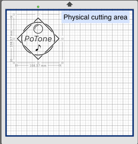
1. Open png data in Silhouette Studio
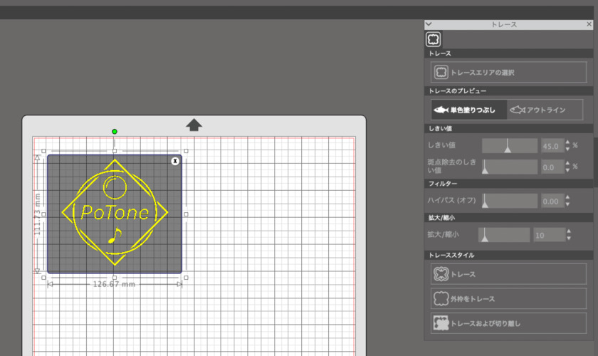
2. Panel > Trace and adjusting parameter to trace the data like "threshold" or "filter" and get clear outline.
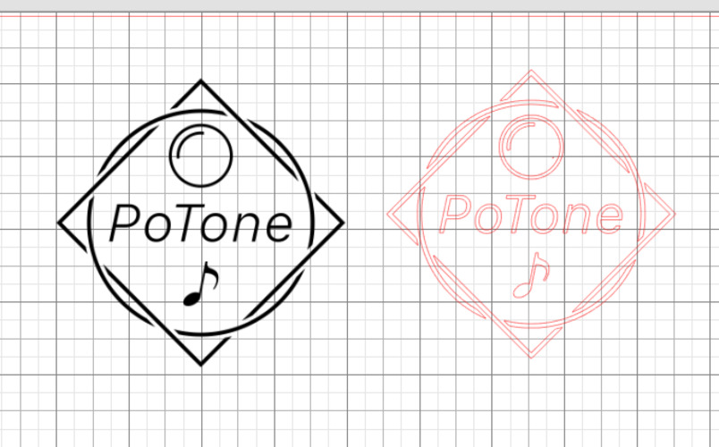
3. Get outline data in red color.
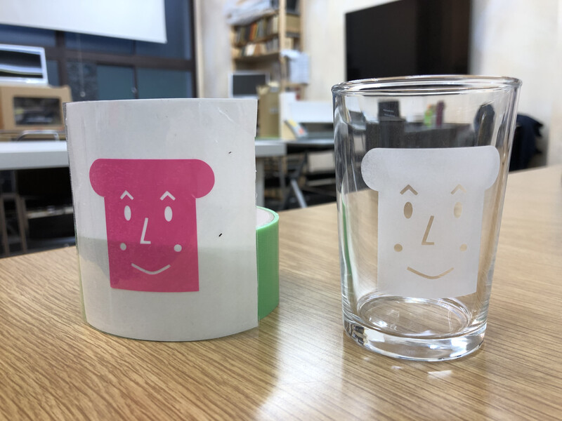
Vector Image: "Breadman(食パンマン)"
This is the symmetric bread-man(しょくぱんマン) that I designed in Fusion360.
The bread−man(しょくぱんマン) is a very famous hero, the best friend of main charctor of Ampan-man(アンパンマン), a popular Japanese picture book. The bread-man is my 3 years-old daughter's favorite.
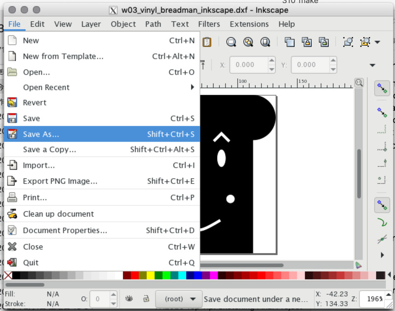
2. Though I used "Shaper Utility" and exported SVG file, that format (by autodesk SVG) could not be imported to Silhouette Studio directly.
So, I opened the SVG in Inkscape and export it into DXF format.
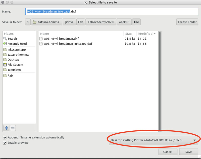
3. DXF R14 format was exported from Inkscape, then imported to Silhouette Studio successfully.
4. In design view of Silhouette Studio, I adjusted size or alignment of data for cutting.
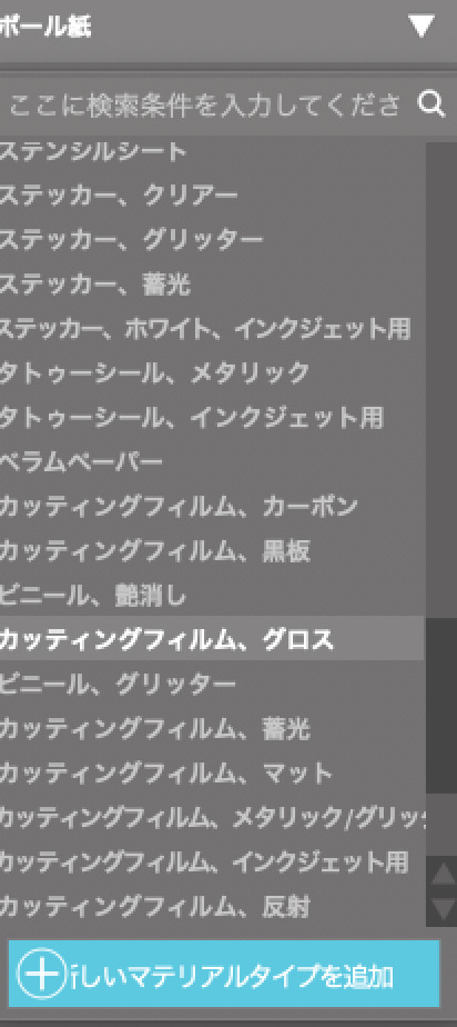
Vinyl Cut
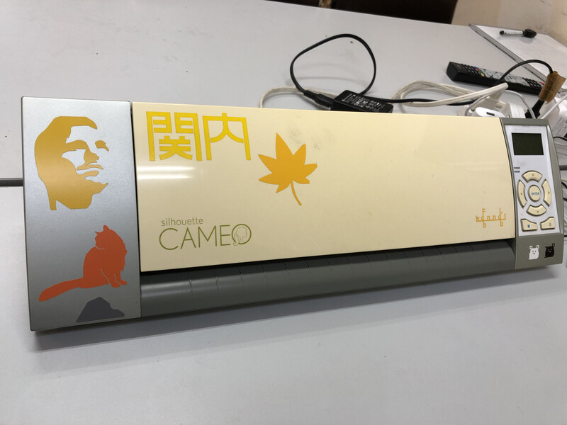
1. For cutting the sticker, I used CAMEO by Silhouette, a vinyl cutter at Fablab Kannai.
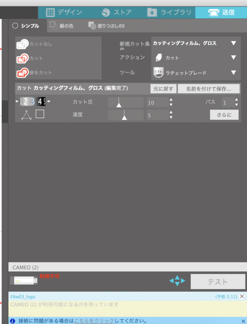
2. Firstly, I tried to cut the sheet with sticker in "3" value of cutting pressure. However, in test cut, the sheet could not be cut out. The pressure was weak.
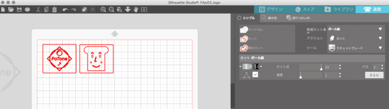
3(1). Set cutting pressure into "4" in software.
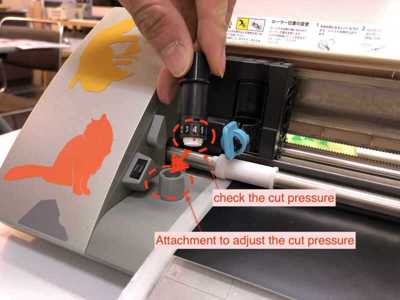
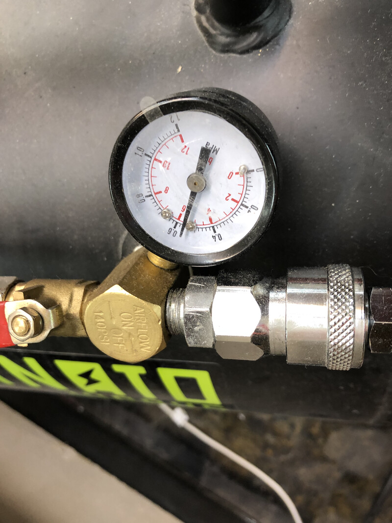
3(2). For adjusting the pressure, user needs to set it physically.
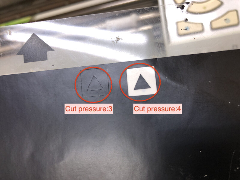
4. Test cut again. Cutting pressure into "4" works!
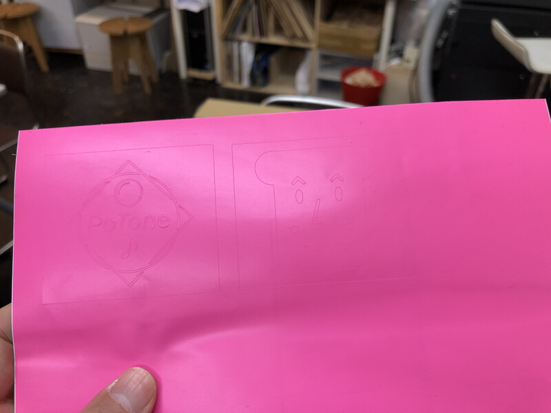
5. Completed to make the sticker!
Sandblast
Fortunately, Fablab Kannai has a machine to make sandblast product. I try to make sandblasted glass.
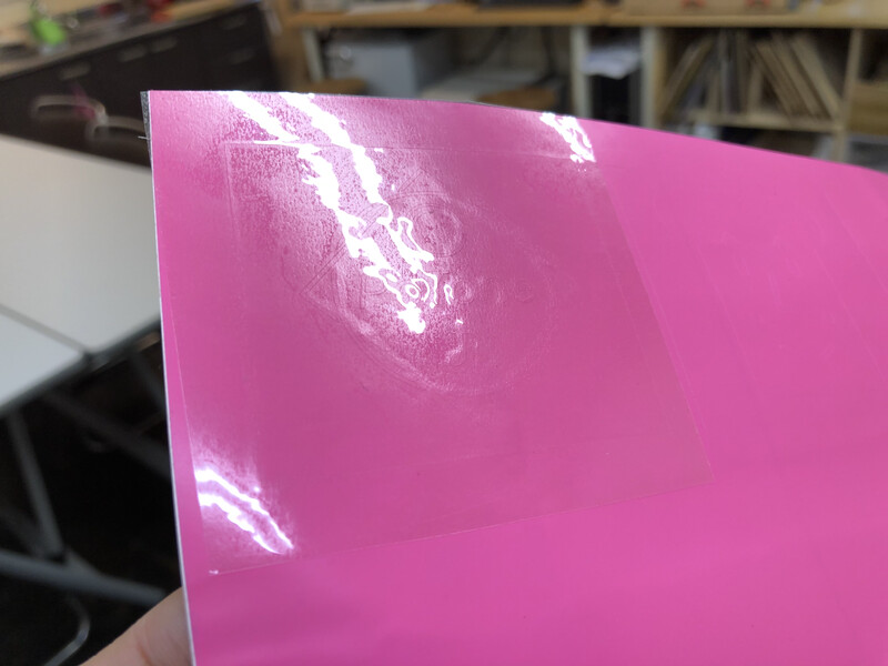
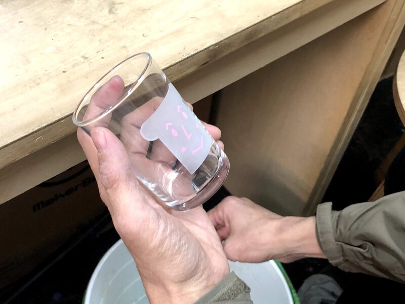
put the coversheet for pealing off the sticker cover easily.
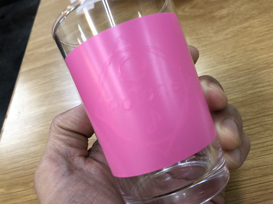
put the sticker and peal off the blasting area carefully using pin set
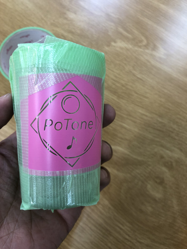
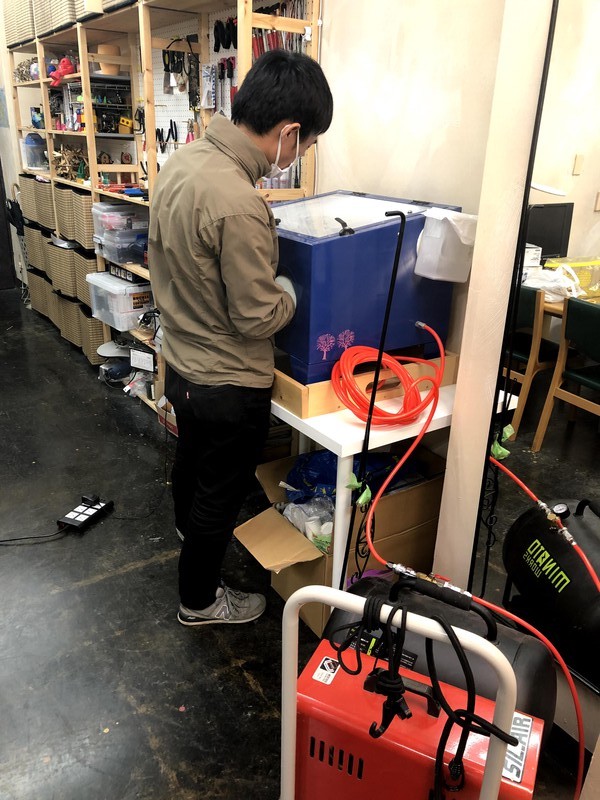
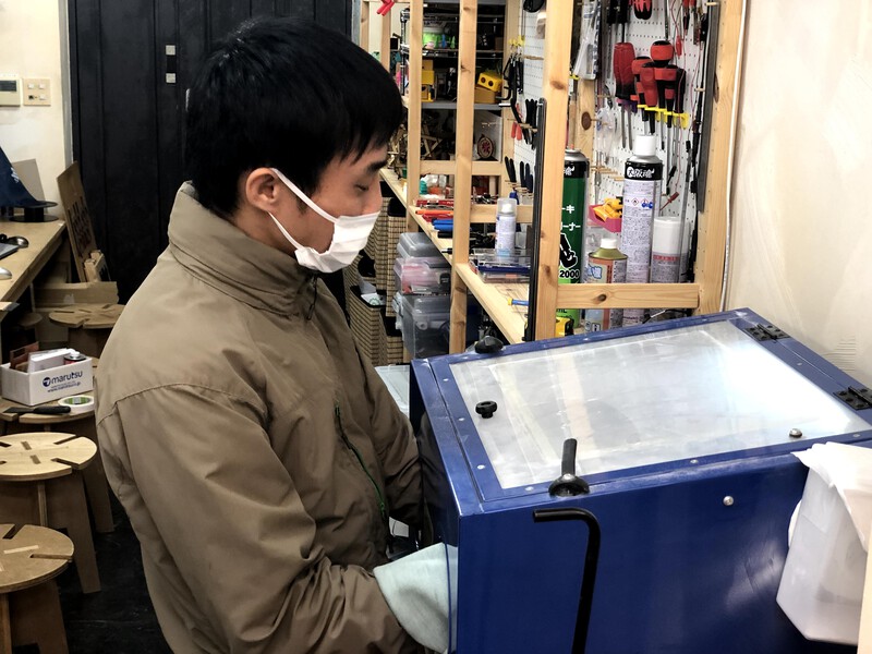
Sandblast machine is dusty... It's necessary to wear a mask.
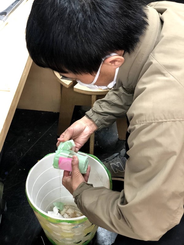
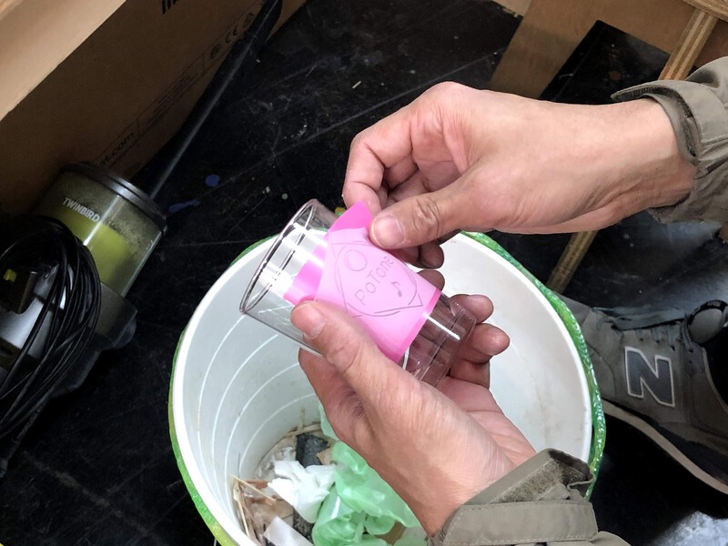
omit the cover sheet above trash box.
Lessons Learned
- Though parametric modeling is very useful, but I need to consider how effectively use that. Too much constraints in modeling causes unexpected behavior in tools and outcomes.
- I learned about character of materials and machine. 3mm cardboard sheet is not so stable that I made a kerf a little bit(0.0X mm) larger than calculated size for construction strength of kit against gravity.
- Vinyl cut and sandblast provides good exercise for making a product in good shape in short cycle development.
Files
References
- FabAcademy 2019 Kannai Group Assignment page
- Universal Laser System VLS2.30
- Corel Draw
- Silhouette Studio
- Shaper utility