4. Computer controlled cutting
New week, new chapter. Now it’s getting serious. The goal this week is to get cutting. We’ve learned how to use several different machines to do a variety of tasks. Some of those tasks were a group effort, and some we did on our own.
Cutting vinyl
The vinylcutter is a simple machine that can do a lot. In my first two goes at the FabAcademy, I used it just to make some stickers, and that was that. After my second FabAcademy attempt, I had the opportunity to take my FabSkills to Africa and teach a workshop there on inflatables and soft robotics. The vinylcutter featured heavily in that workshop.
Making stickers
This was the most straightforward part of the assignment. The First step was to receive a vector graphic of my lab’s logo from my PostDoc, whose design it was originally.
![]()
The original SVG file is available here.
(This was all a bit of overkill - I’ve since discovered a much easier way to do this.)
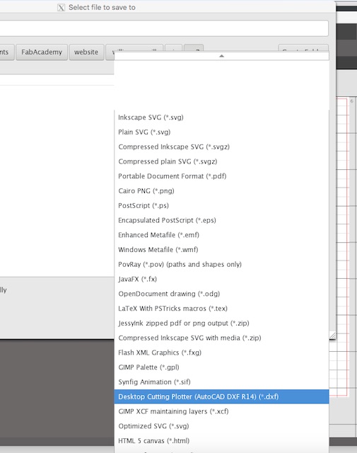
Hardest part of that was getting Inkscape and X-windows to work on my Mac. After a certain amount of swearing and plenty of patience, we got there in the end. Once in Inkscape, I then had to save it as a DXF file using the option shown below.
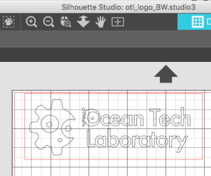
Then it had to be opened with the vinyl cutter’s own “Silhouette” software, which loaded it as an outline. This was then surrounded with a rectangular box, as shown.
This was ready to be sent to the machine. A grey coloured vinyl sticker sheet was sourced and stuck to the template provided with the machine, taped in place along the edges with masking tape. The template and vinyl were then fed into the cutter. The cutter blade was tested on a small piece, and we found that it had to be set on depth “3” in order to cut completely through the sheet.
The printer was then turned loose with the file and it generated the desired pattern. On completion of the cutting, the vinyl and template were removed from the machine, and sticker was peeled off the template. First the negative was peeled back, carefully using a sewing thread cutter to hold down the delicate parts, and then the same thread cutter was used to separate the centres of letters and some of the contained parts of the logo. These were then stuck onto the lid of one of the lab’s Macs.
![]()
Masking tape was then laid over the positive cutout and peeled back with all of the delicate elements intact, and used to transfer the logo to the lid of a second Mac.
The final result is gorgeous.
![]()
FabSkills in Africa
I took these skills to Africa and ran a workshop on Fashion Design at the Ho Technical University, in the town of Ho, in eastern Ghana.
The 4th Dimension Workshop was based around some practical exercises that are available online at the soft robotics toolkit. The goal was to introduce the students to the 4th Dimension (in this case, Movement) in fashion design. Soft robotics provides a simple and inexpensive way to add surprising and innovative movement to clothing and other fashion accessories.
The first exercise was to make an inflatable wrist splint. The objective wasn’t so much to make a splint as to show how to make variable compliance spars that could be built into clothing. The splint provided a simple manufacturable object that served to demonstrate the concept of stiffness through inflation pressure.
In that first workshop, I tasked the students with drawing and cutting out their own templates for a wrist splint. The resulting variation in the various cutouts made it difficult to ensure that the students’ attempts would actually work. So for next time, I’m thinking I’d rather do the cutting with a vinylcutter. So to get ready, I thought I’d have a go at cutting one out.
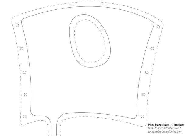
The template came from this site. The downloaded zipfile includes a PDF file called “Template”. To use this drawing with the vinylcutter, the PDF has to be converted first to an image file, so that the vinylcutter software (Silhouette) can work with it. The easiest way to do that is to use a website like smallpdf.com. The converted image looks like this:
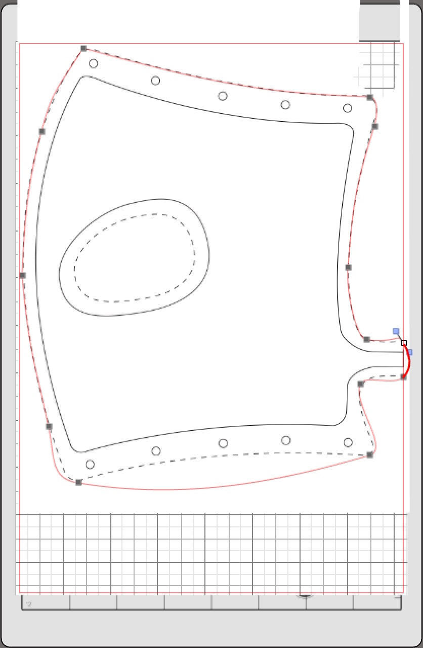
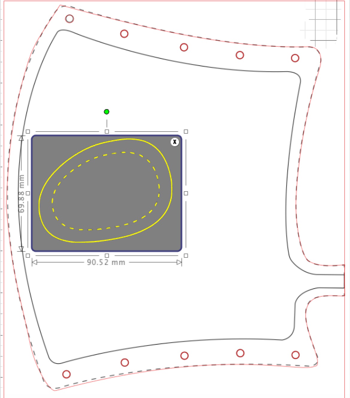
The JPG file can be opened in Silhouette, then turned 90 degrees to fit the print area available. Then the text needed to be deleted using the eraser tool. I needed to make two parts for the splint. One is represented on the template in dashed lines - this is what will be cut in vinyl. The second is represented in the solid lines - this will be cut in paper. In the end the paper will serve to separate the two halves of the splint when they are heatwelded together. To trace the two templates, I used the shape drawing tool, then moved the apices around, changed them from smooth to corners, then fit the resulting spline curves using the simple tools in Silhouette. I used the Silhouette trace function to pick out the ten little holes and one of the larger thumb holes.
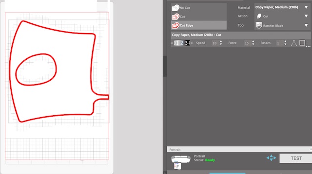
The final step is to get rid of the underlying graphic and tidy up, ready to cut out on the vinylcutter. The paper insert was cut using the default settings for copy paper, as shown below:
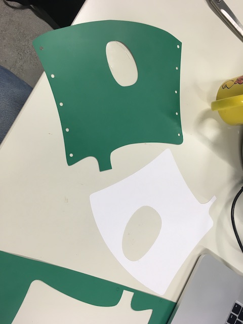
The vinyl outer part was harder to cut, as I’d never tried the particular material before, so it took a few experiments to find a setting which cut it properly. In the end, I could have applied a little more force even, as the cuts didn’t completely go through the hard plastic backing.

The final parts came out ok. I’ll need to peel the backing off the vinyl, then find an iron to heat-weld the seams.
I’ll put the final product together later this week.
Epilogue
The vinylcutter has found its niche in my regular lab. We’ve used it as part of the MINT Girls workshops we hold every summer to encourage girls and young women to consider STEM careers. We’ll also be taking it to Kenya later this year as part of another episode of the inflatables and soft robotics workshop. And finally, I’ll be looking forward to seeing next September what the students in Ho have done with the machine I left them last year.
Downloads
The Silhouette files for the splint are available here:
Laser cutting
The “big” lasercutter we have in the lab is a 60W Epilog Fusion machine. Here’s an artistic shot from two years ago showing the front panel.
![]()
Operation Procedure
The description of the standard operating procedure is to be found in our group assignment
Preparing the print job
As far as the controlling computer is concerned, the laser cutter behaves just like a printer. The trick is to prepare the job with the correct attributes so that the printer driver knows how to interpret the image.
The first step is to distinguish between raster and vector graphics. Scans covering a surface area are typically done with raster graphics, while lines are generally done with vectors. The printer driver can handle both, even in the same job, as long as the settings are appropriately entered.
Simple etching & cutting
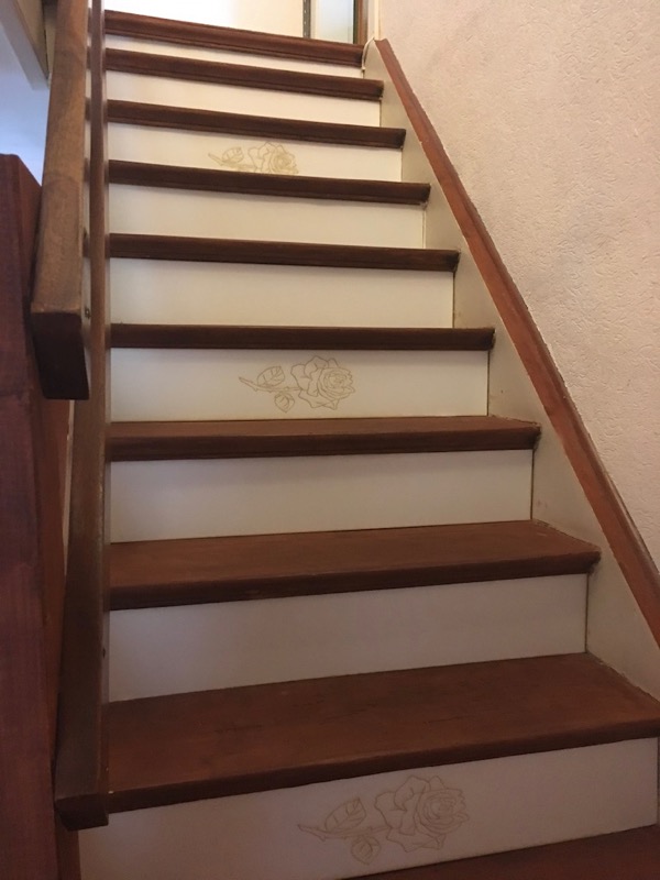
My individual laser cutter project this year was to make some risers for the stairs in the house my wife and I are renovating. The stairs were covered in a layer of horrible carpet which had been glued to the wood, which had been painted in the 1950s fashion with a thick coat of red floor paint. The carpet came off ok, but the glue residue and paint removal was a backbreaking and soul-destroying job which involved a lot of sandpaper disks and a rotating wire brush tool for my power drill. Here’s the state of the staircase after the dust had settled.

Without the assistance of gravity, the risers would have been a nightmare to sand back to the wood, so I gave up and decided to cover them over with white vinyl-coated MDF. This is where the laser cutter came in.
The staircase wasn’t particularly high quality when it was made back in the 1950s, and none of the steps are exactly the same dimensions. I therefore had to measure every step and take into account some of the less-than-straight edges.

I drew the risers in Inkscape. For the non-rectangular risers, I used the edit nodes tool. To spice up the staircase a bit, I decided to add some artwork to some of the risers. I downloaded a line-art rose from the net, and imported it into Inkscape. Here’s a typical screenshot from Inkscape.

Then it was off to the scanner station. The Inkscape drawing was saved as a DXF file, and this was imported into Rhino, where the two operations (cut and engrave) could be assigned to the graphics. The trick was to define the thickness of the box line to 0,001mm, which indicates to the lasercutter that that line is to be cut right through. The engraved lines were given a thickness of 1mm.
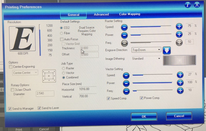
The file was then printed from Rhino. Using the settings described by the team on their MDF info-board, I set the print dialog as follows.
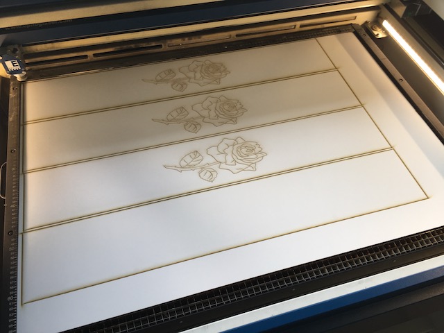
For some reason, the lasercutter didn’t enjoy the “combined” job type, so for the rose-containing pieces, I did the job twice, first to engrave the rose using the raster settings, then second to cut out the riser using the vector settings. Partway through the job, here’s what they looked like coming off the lasercutter.
Due to measurement imperfections, the cutouts weren’t perfect fits to the spaces on the stair risers, so they didn’t just pop in and I had to cut them down a bit by hand to fit them into place. The final product looks pretty good.
Downloads
The DXF files for the roses are available here:
Safety
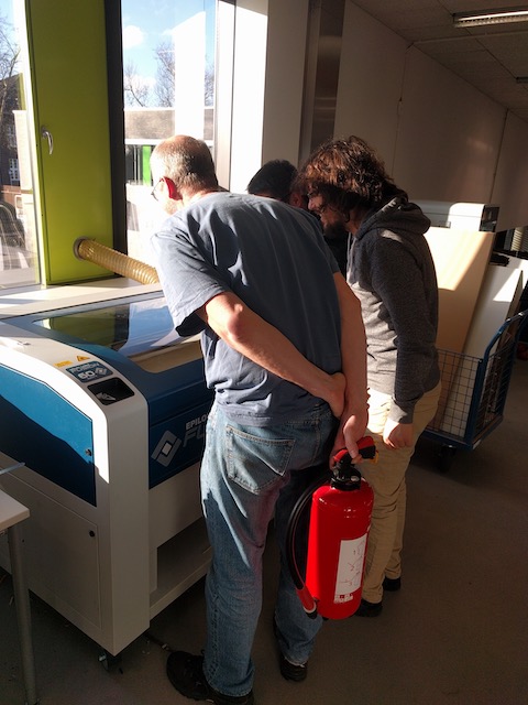
Safety around the lasercutter is paramount. Our instructor had got sidetracked with something else while we were making our first cuts, so I casually went over and picked up the fire extinguisher from the wall. Carrying it quietly across the lab quickly got his attention!
Parametric Design & Cutting
The ongoing background story for me these past fourteen months has been the renovation of the old house my wife and I bought in late 2018. Our vision for the kitchen is a cross between a farmhouse and an industrial look. The concept is for the plumbing and electrics to be external to the walls, rather than chased into them. Building standards will require the electrical cables to be covered with plastic tubing. Something like the following, which I found on pinterest:

However, after coincidentally seeing what that looks like for real in a friend’s old house earlier this week, I’m thinking the look needs a bit of softening, hence the motivation for this week’s project, which is to cover over the pipes with living hinge conduits.
Parametric Design in Fusion360
In Week 2 I did parametric design in OpenSCAD. In previous years, I’ve tried SolidWorks as well, though that failed when I didn’t have access to Excel on the Windows installation on my Mac. I’ve seen people using FreeCAD with Excel, and at some point, I’ll teach myself to do that too, but for this week, I’m going to stick with my “go to” CAD package, Fusion360.
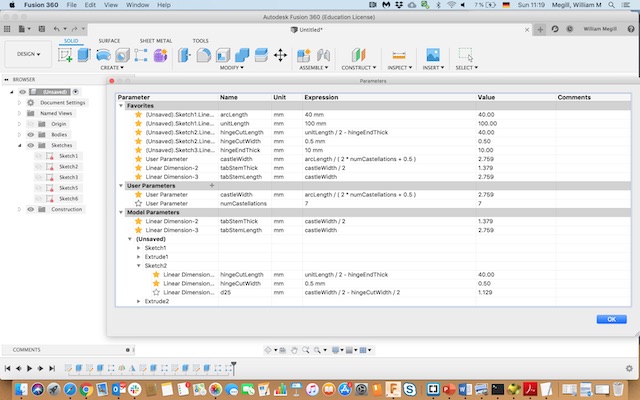
Parametric design is built into Fusion360 right from the start. As soon as a dimension is specified using the keyboard, rather than drag and drop in the sketch, it is saved in the “change parameters” database (that probably has a better name), which is accessed through the modify menu.
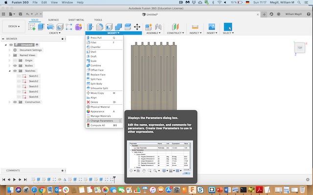
The “change parameters” database system gives generic names to every specified dimension. These can be changed in the name box. The yellow star to the left allows them to be promoted from their individual parts out into the “favourites” where it is easy to adjust them on the fly. There is also the option to create user parameters not related immediately to any dimension. Finally, all of the parameters can be given fixed values or can be determined through mathematical formulae involving other dimensions or the user parameters.
The process of designing the living hinge in Fusion360 went like this:
-
Create a new component
-
Set up a sketch of the cross-section of the trunking, with a semi-circle over two rectangles. Set the thickness of the material. Remember to use the keyboard dimensions (this step isn’t crucial, as the dimension tool can always be used later, but it does speed things up)
-
Extrude the tunnel-shaped sketch to make a first, solid trunking module.
- Using the Sheet Metal command set, convert the solid body to sheet metal, and then unfold the curved part.
- Open a sketch on the flattened section and draw one segment of the living hinge.
- Open a second sketch on the same section and draw one copy of the tab and socket.
- Use the linear pattern command twice to create the whole hinge and add the tabs and sockets.
- Refold the component.
- Add additional tabs and sockets to the rectangular sides.
- Voila.

The whole of this model is parametric. The primary driving parameters are the width of the cut in the hinge, the thickness of the hinge elements, and the number of hinge repeats. Tab depth, socket design, and overall length of the module are also parametric, and related where appropriate to the parameters of the hinge. Some of the parameters are shown in the figure below.
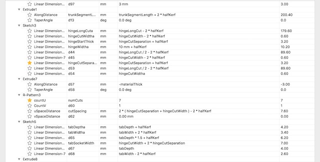
The dimensions have to be updated to take into account the kerf of the lasercutter. This part was just confusing, so took a while to do and debug. The process was to make tabs a bit wider and cuts a bit narrower, using the parameter “halfKerf”. A typical sketch from Fusion360 is shown next:

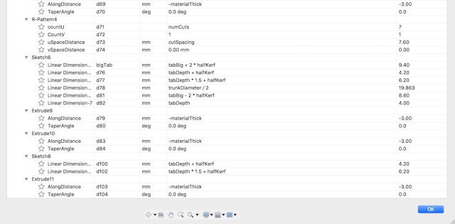
The full list of parameters is shown below.

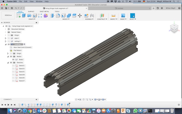
The final module looks like this.
Additionally I made some corner parts.
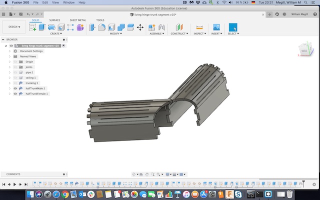

To prepare the parts now for actual cutting, first, export the part face by making a sketch in a plane parallel to the face to be cut, then right click and export as DXF. Next, import to an online DXF file viewer and create some jpgs (so we can see what’s going on):
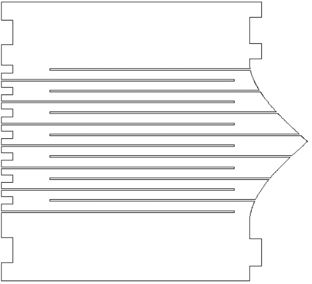
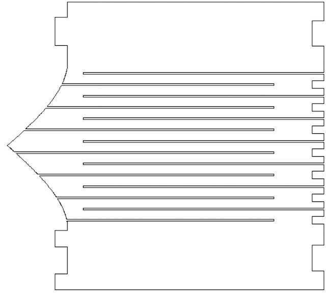
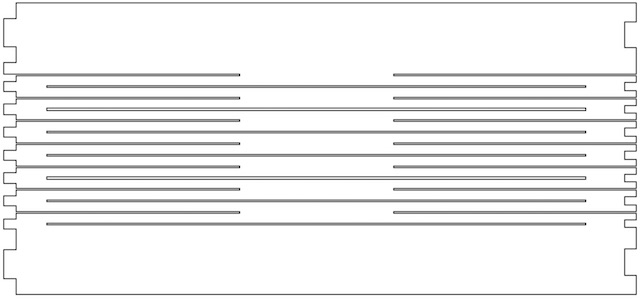
The DXF files themselves are available in the downloads section further down.
The DXF files are imported into Rhino on the computer that runs the lasercutter. The drawing is “exploded”, and any extraneous markings are removed. The the drawing is “joined”. Then the data is sent to the lasercutter using the “print” command.
The lasercutter
Our lasercutter is a 60W Epilog Fusion. The trick with cutting materials is to get the settings right. Too much power, pulsed too often, will cut through thick material but burn thinner stuff. Too little power, pulsed infrequently, will only literally scratch the surface. The settings I used for cutting 3mm MDF were as follows:

The “set” button is used to place the drawings relative to the lasercutter bed. Then the job can be sent to the cutter.
The cutter has to be focused. For this there is a small aluminum triangle that hangs from the laser head. The bed is placed so that the tip of the triangle just touches the material to be cut. Then the laser is set in the top left corner of the material to be cut, and the job can be started.
The result of the cutting exercise looked like this:
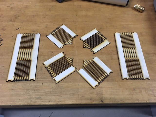
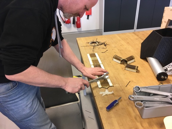
These were then carefully assembled using the correct tools:
And two arrangements are possible:


The final result looks ok, but I’ll need to redesign the joint at the top of the intersection so that it goes together better. Also, I need to remeasure the kerf so that the joints fit together better, without the need for a wrench!
Downloads
The Fusion360 file is available here:
The DXF files that were fed to the laser cutter are here:
Group Assignment
Here is the link to our group assignment. It doesn’t look quite finished. Once we get back to the lab, we’ll return to this and get it cleaned up properly.