Week 8 (Embedded Production)
Week 8
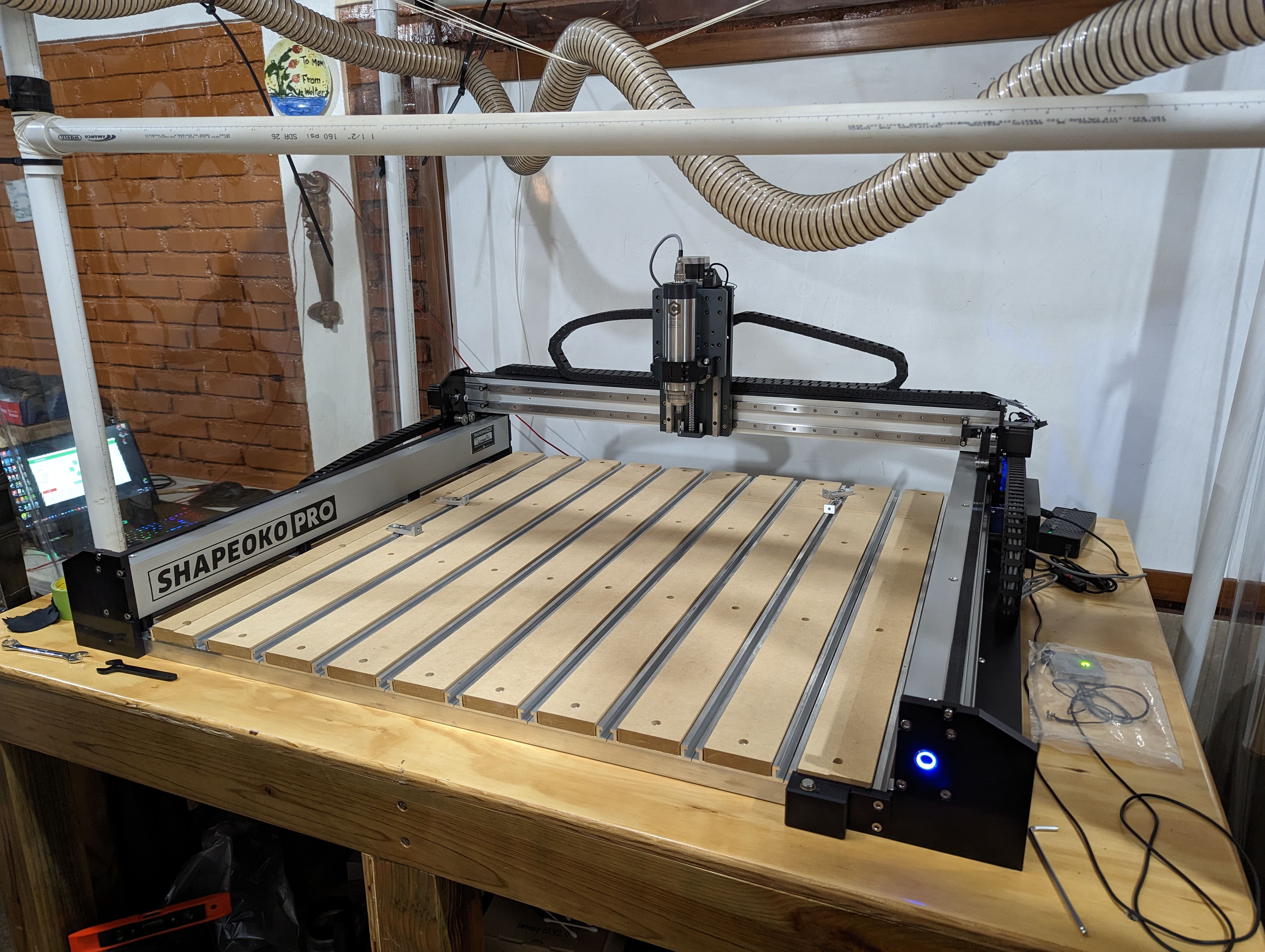
I did some of the needed precautions in WEEK 7 after building assembling my Shapeoko Pro XXL. Remember we need to properly tram your CNC to keep the needed tolerances to mill a PCB. Another really important precaution is making sure you’re damping vibration as much as possible. Structurally this CNC is amazing damping vibration because it has metal linear rails in every axis, many T tracks (helps with rigidity), VFD spindle, heavy duty Z axis components that hold and move the spindle and its resting on a really heavy table (Got to WEEK 7 for more Info.). All of these variables help positively the capabilities to mill a PCB but I took more precautions. Measuring the Copper Clad Laminate with a micrometer so that the bit doesn’t plunge in the spoil board. If this happens more or likely the bit will snap. Make sure your spindle has a 1/8” shank to have a less restrictive tool selection that could be used to mill the PSB.
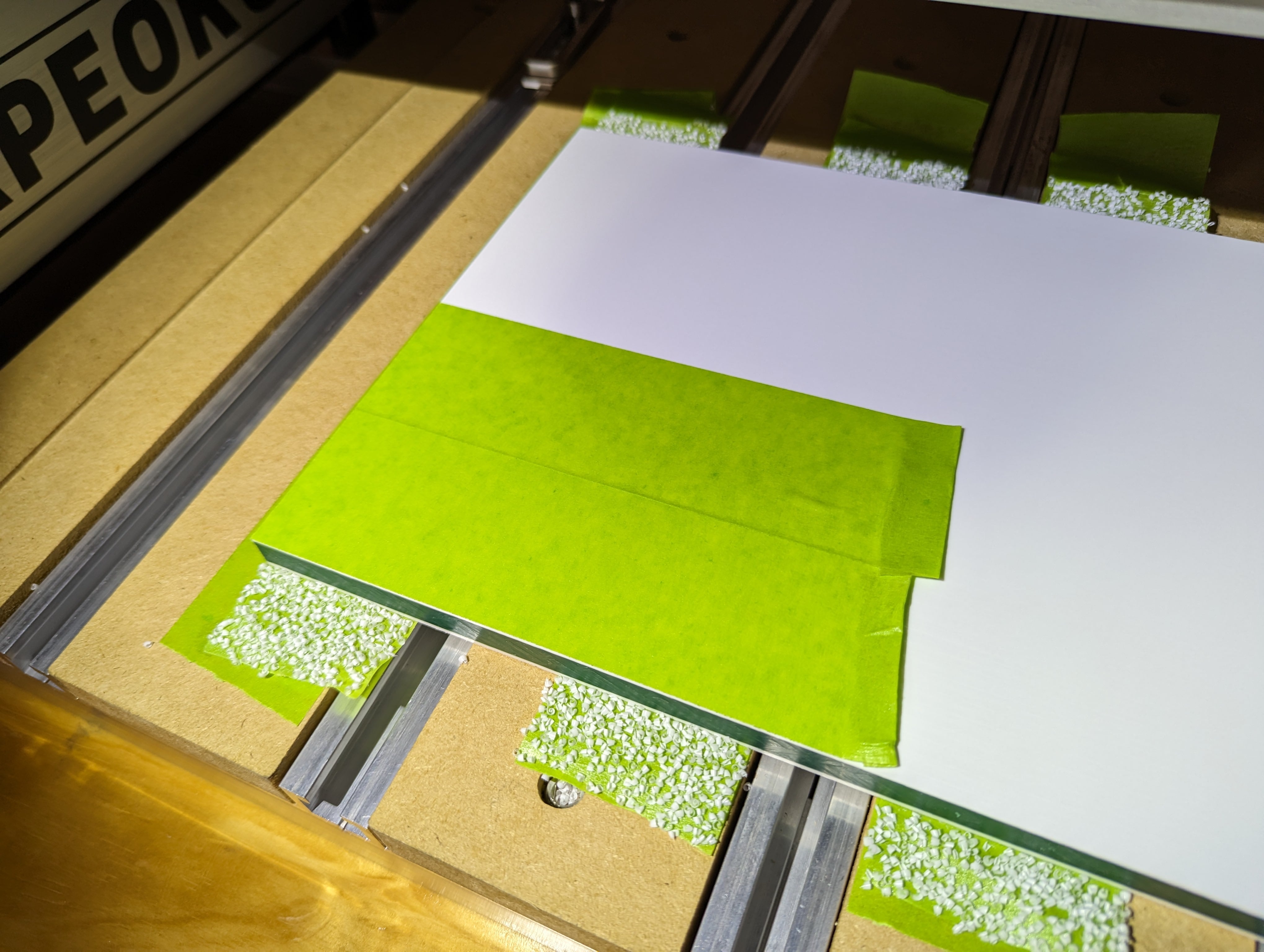
After that I added a special surface that covered the T tracks with a HDPE board. Instead of using clamps I used the painter tap technic with super glue to make sure most of the board (specially the middle) was having full contact with the spoil board. I placed the HDPE board near one of the corners of the bed to have more rigidity to prevent vibrations. After that we need to square the surface of the HDPE board. Please notices the light reflecting on the HDPE board on the following picture. You’ll see the marks left by the CNC bit after the milling process and in the vertical video you’ll see the same reflection. See how fast I’m moving my hand and listen the sound it’s making.
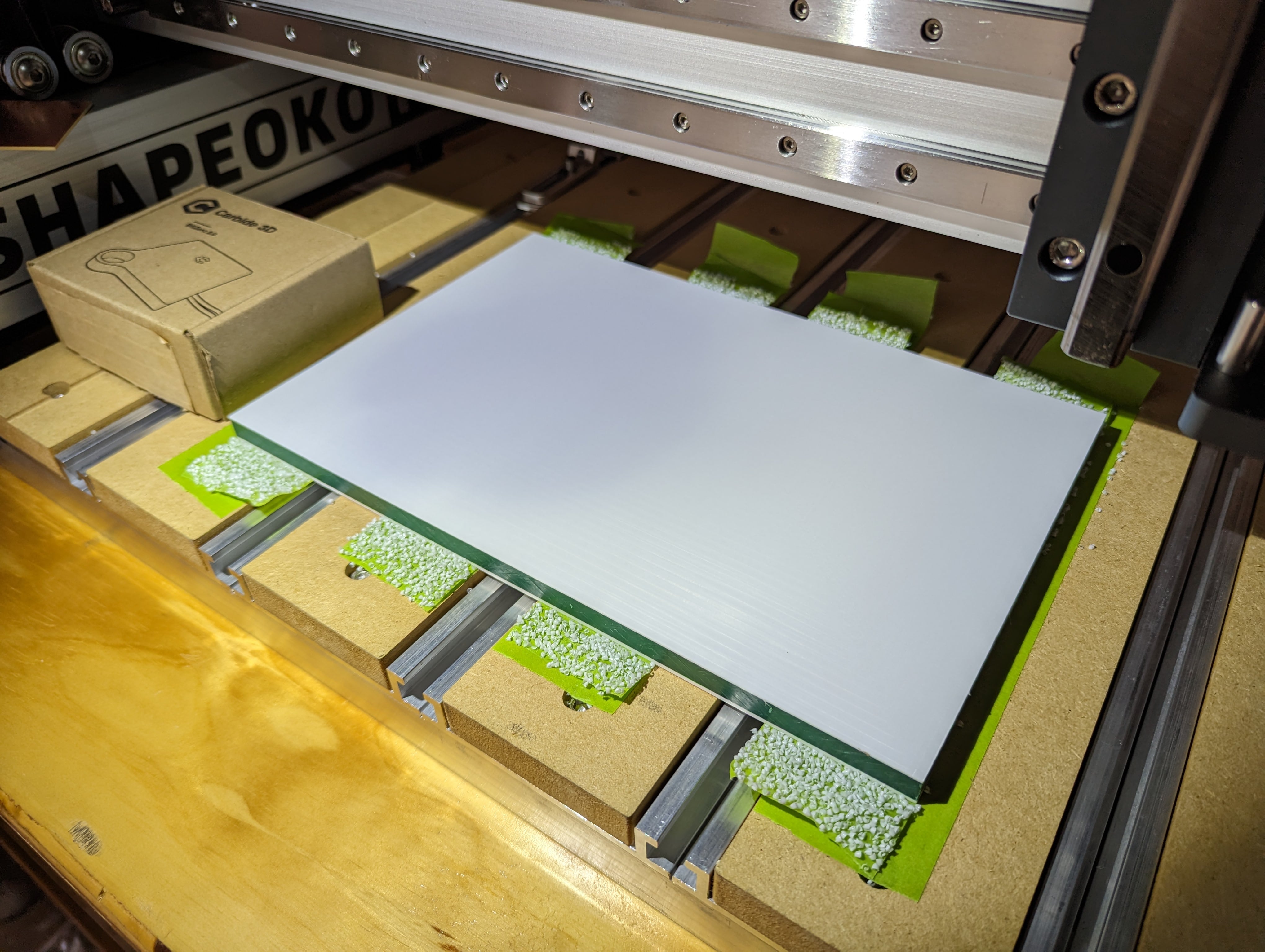
Then we use the same painter tap with supper glue technic to secure the Copper Clad Laminate. Before milling make sure to set your Z zero properly. If the final operation is successful the tap will act as an “union skin” preventing the bit having contact with the HDPE board and securing the PCB after the cut.
Week 8
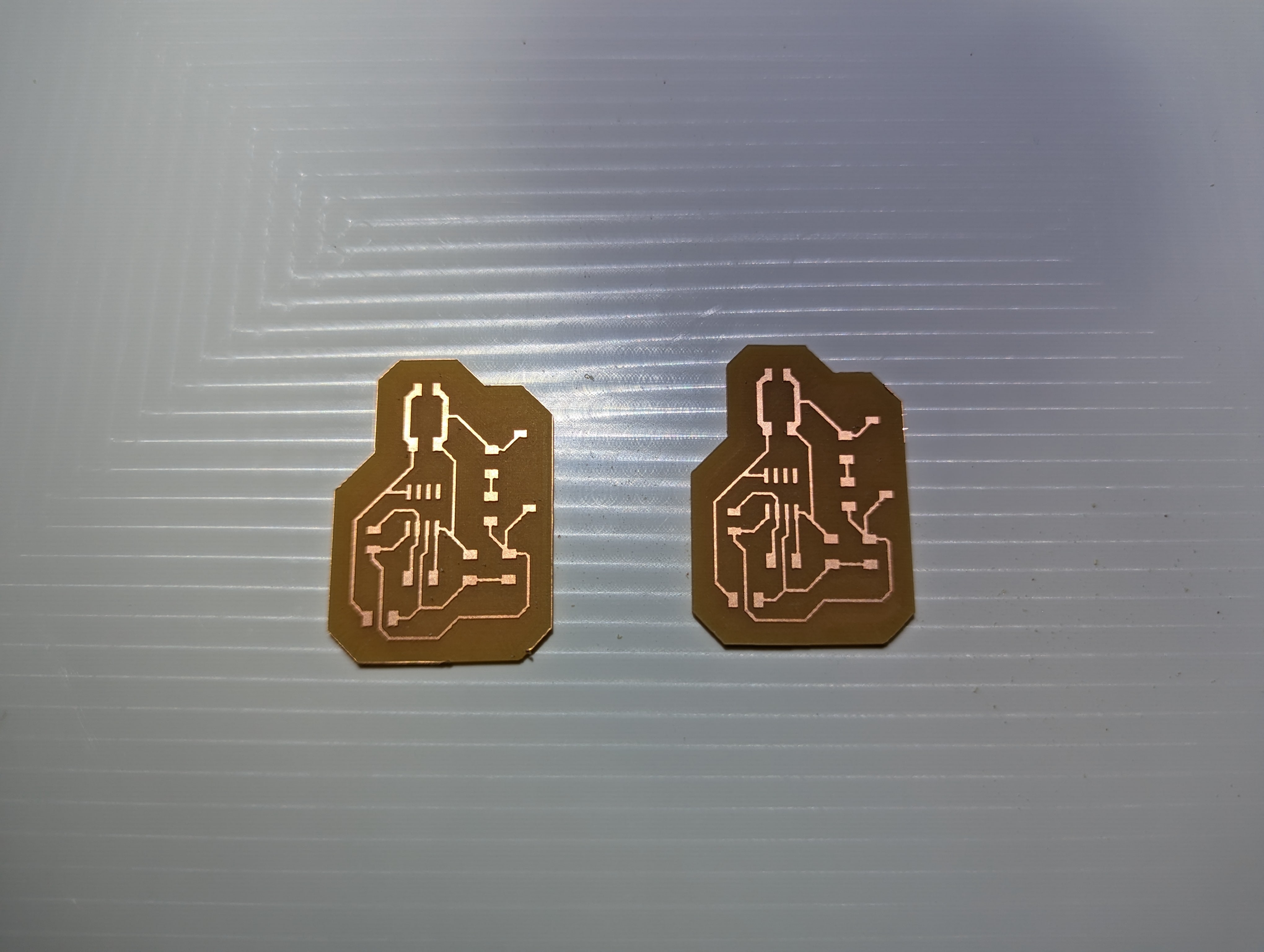
Do to the global and local problems I don’t a lot of choices for MCU selection. I have a limited amount of ATtiny 1614. I’ll make a PCB that has I2C communication, servo motor pins, and pins for a sensor. To make this PCB I’ll be using my Shapeoko Pro. Then I jumped in eagle to make the schematic and trances for my PCB. After finishing this I exported the trace to a png file.
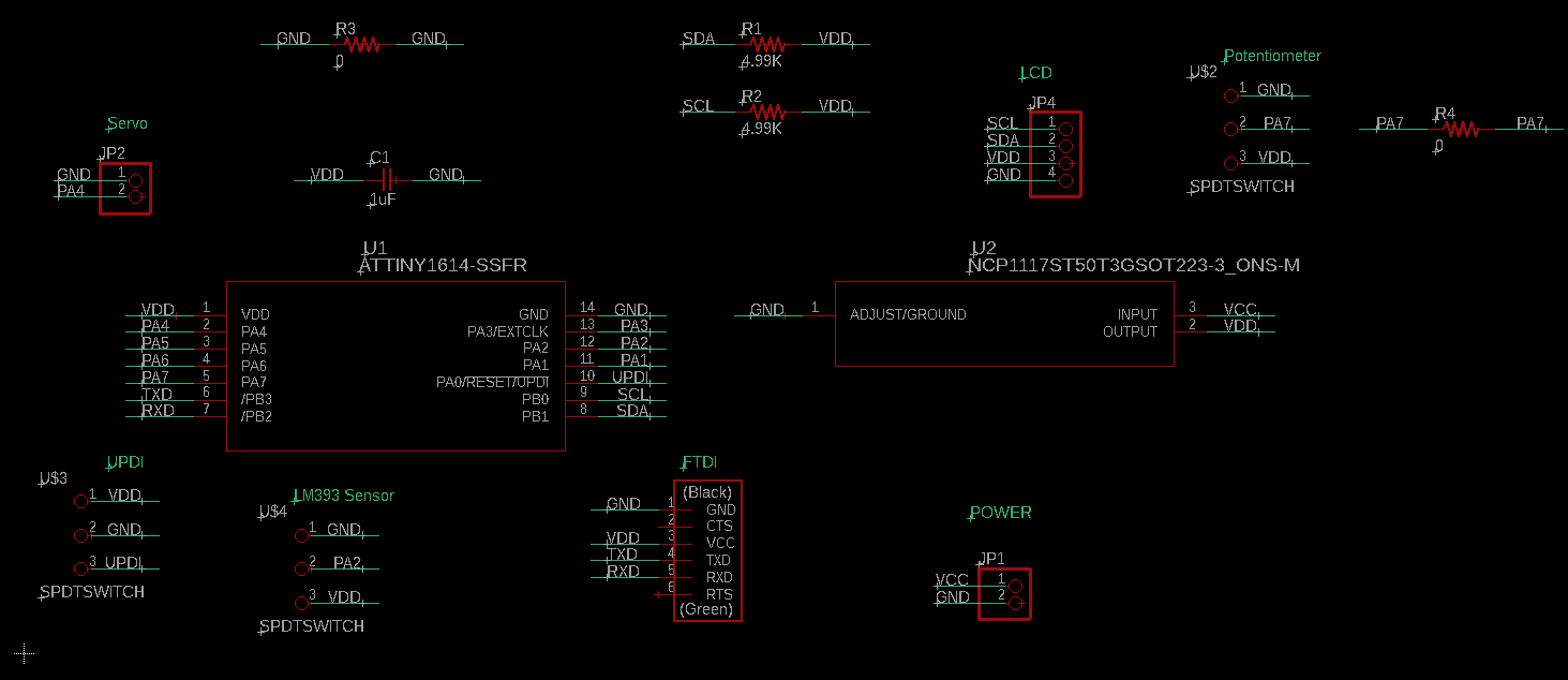
In the design process of this PCB, I received a lot of support from my friend/instructor Adrián Torres . I also studied a lot his Adrianino. In my PCB prototype I needed to gain more hands-on experience to add the appropriate modifications if needed. For started I added some pins to power the board with a battery if needed, FTDI port for serial communication with my laptop and 5V input, I2C port for easy connectivity with a variety of input and output devices, and easy access to UPDI port for programming. Thanks to a mod made by Adrian we can program the PCB with only 3 pins. No need to connect the FTDI for power while programing the board.
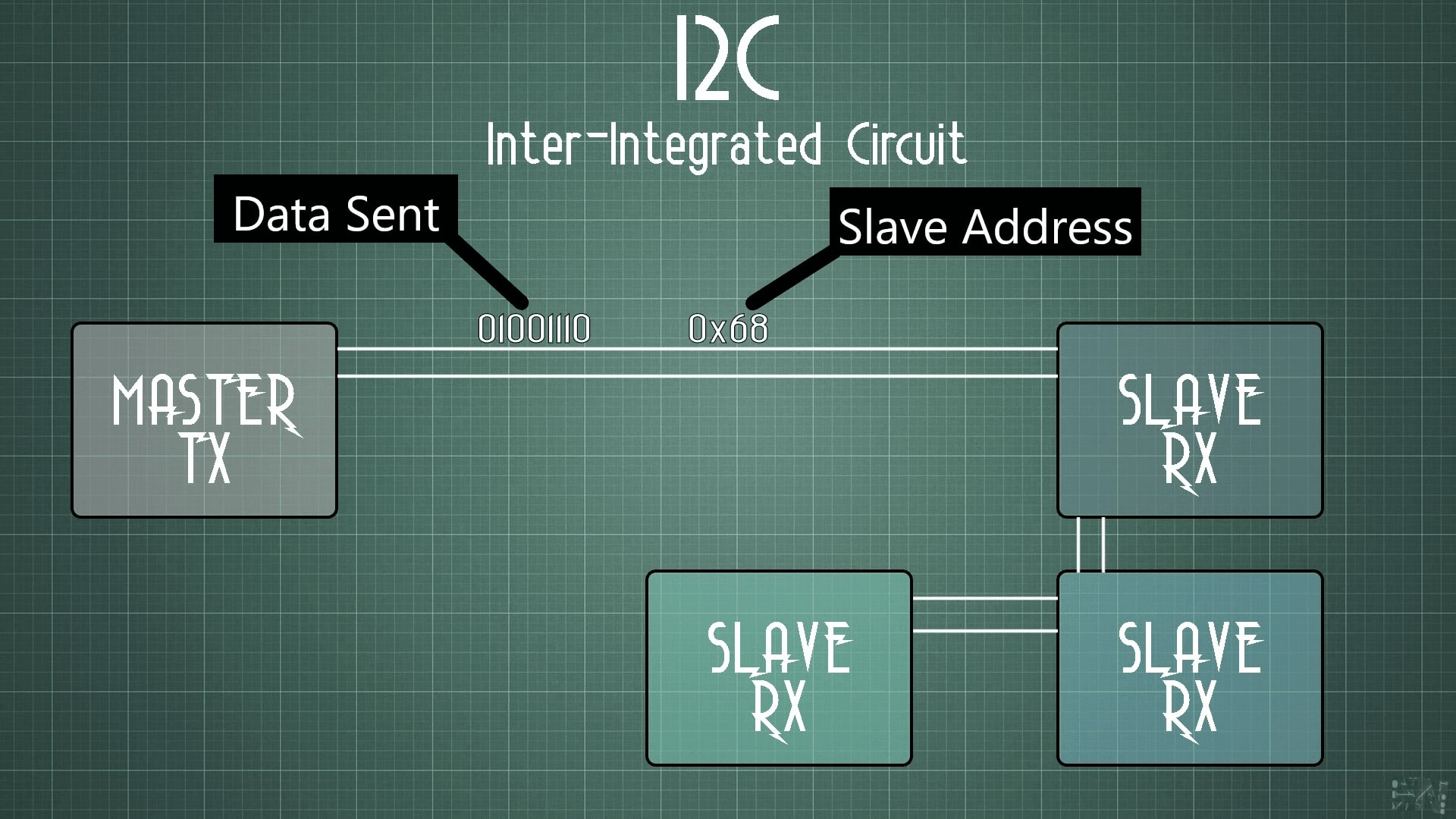
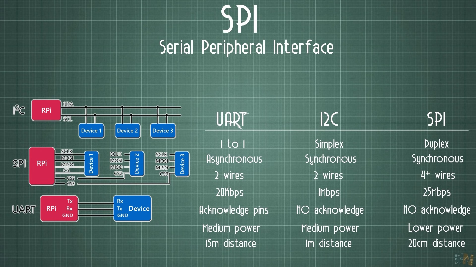
Diving more in I2C serial communication, I’ll be using my friends Adrián Torres Repo as a reference. I’ll also used Electronoob’s video that covers a better explanation on networking using I2C. I2C is a type of synchronous (needs a clock to send data) serial communication. What I like of this type communication is that you only need 4 pins to execute it and there is a variety of inputs and outputs that take advantage of it to communicate with the chosen MCU. The pins are VDD, GND, SDA (pin that sends the data) and SCL (Clock needed to send data).
The following screenshots are from the YouTube video of Electronoob’s. They help describe how the concept of the Master and slave devices work. The “MASTER” is the transmitter (TX) and the “SLAVES” are the receptors (RX). To have good communication as a requirement it’s really important that you give each “SLAVE” an address. I2C has a maximum quantity of 127 “SLAVES” in the BUS (main communication lines).
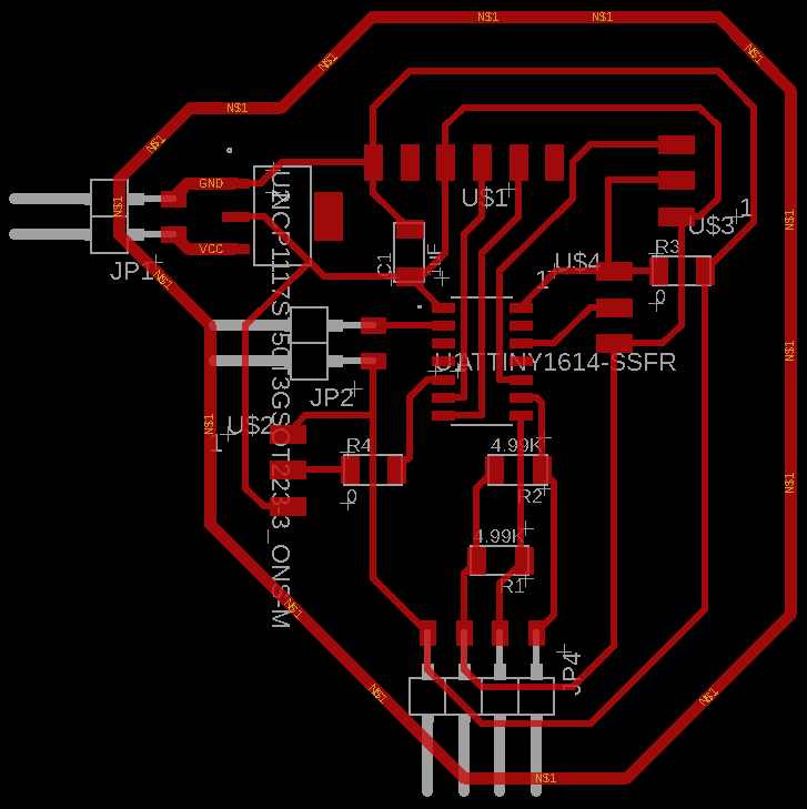
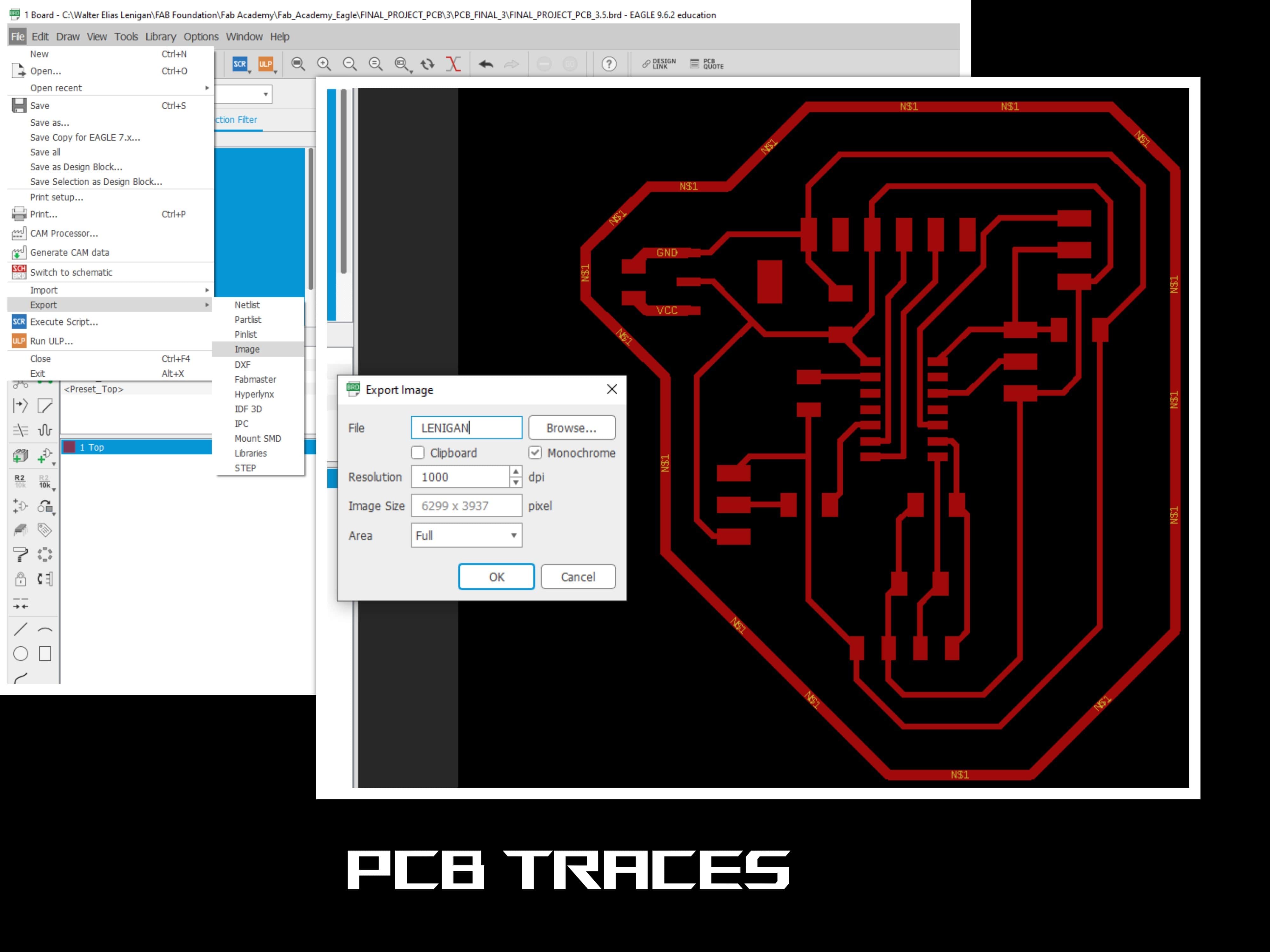
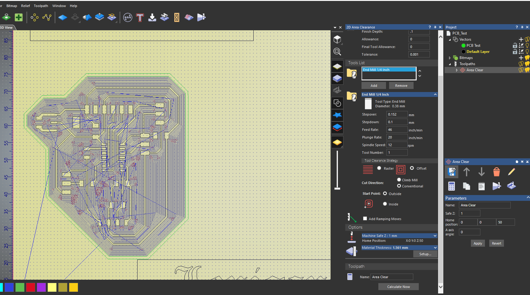
After exportin the monochrome picture I take the file in InkScape to use trace BitMap to generate vectors to import them in Carveco. I used a special end mill with the fallowing parameters: