Assigment #3
Computer controlled cutting
The third assignment to do for the fabacademy is the computer controlled cutting. Unlike the previous assignment (at least at the moment) there’s no application for it in my final project, and therefore I came up with some exercises to test and improve my skills in computer controlled cutting
1 – Vinyl Cutter
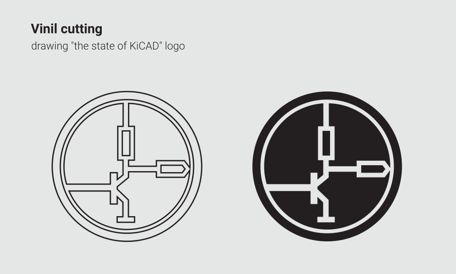
The first machine I’m going to experiment with is the vinyl cutter, a very powerful machines that allows you to cut many materials… To work with this machine I thought about cutting a graphic to transfer on my computer... As you might have seen on my previous assignment I’m really into open-source software, and therefore I’m going to make for myself a KiCAD sticker, inspired by a graphic used to promote an event called “the state of KiCAD”.
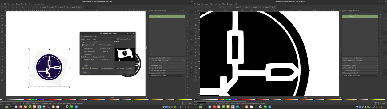
To do that I imported the image I downloaded form the site on kicad. Then I tried to use a “trace bitmap command” to turn the raster image in vectors, but the results of this process was not really good.
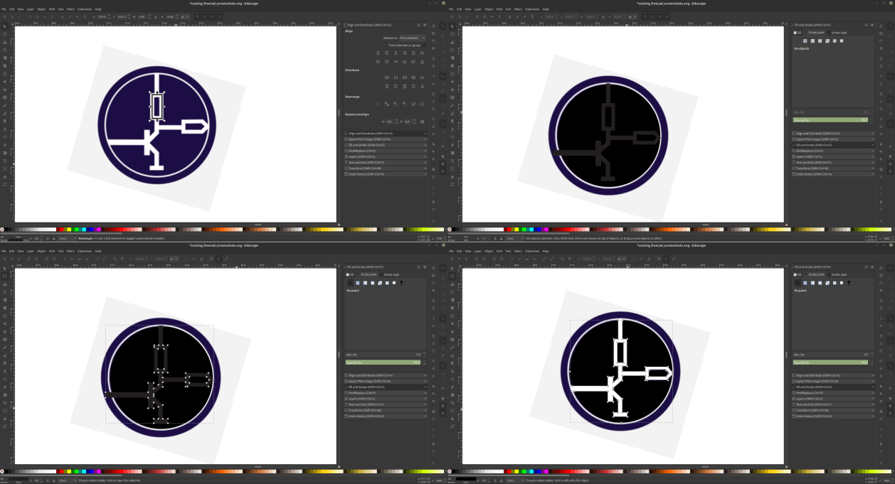
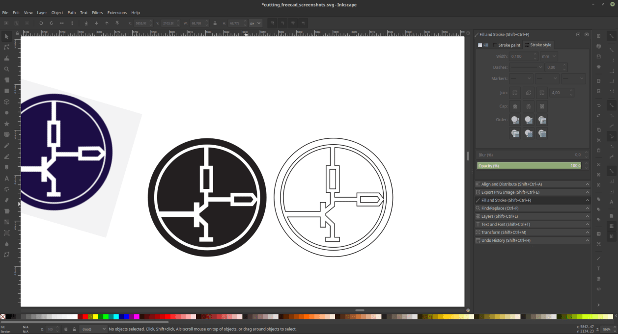
So I decided to manually draw the elements of the logo, to do that I used a bezier curve. Then I worked with the stroke paint to make the lines thick, and used the stroke to path command to turn the thickness of the lines into vectors. Last thing that I did was a series of Boolean operations to turn all the elements into one single graphic to use for my cutting operation.
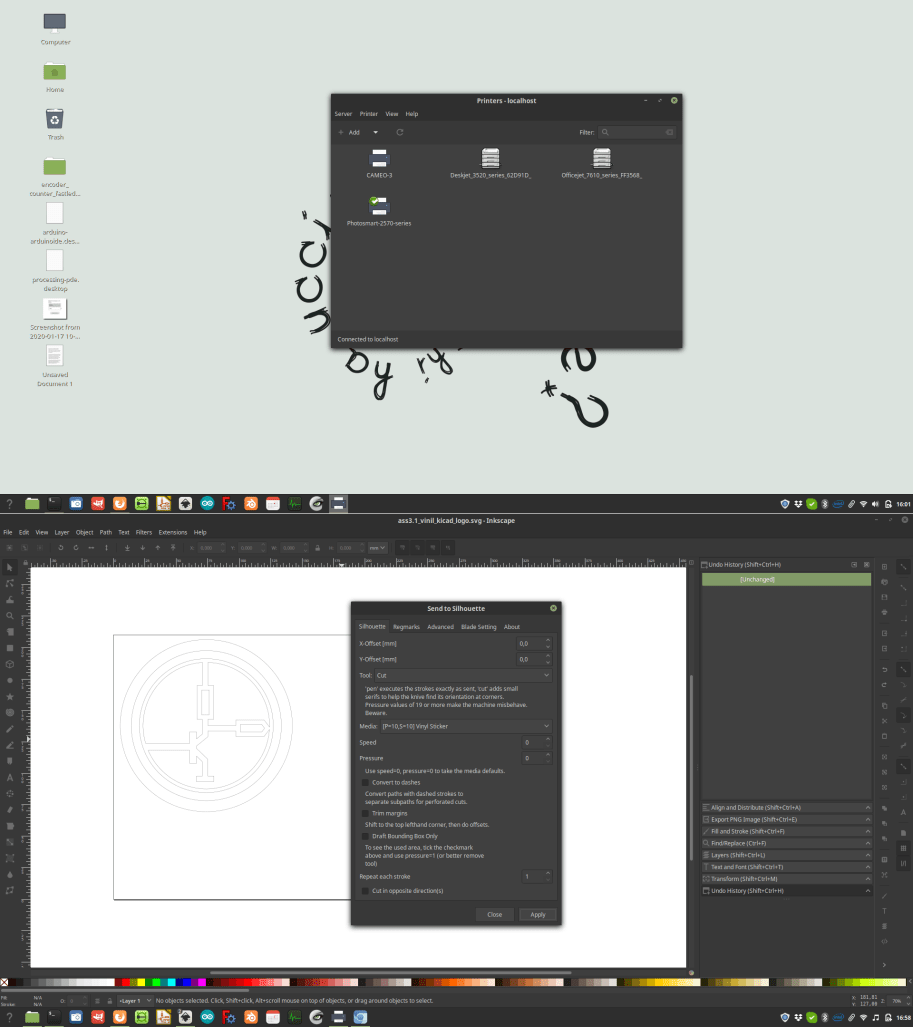
To drive the Crunchlab’s Cameo 3 I used Inkscape with the plug in Inkscape-Silhouette, it is possible to install it via terminal following
this tutorial.
Once the drivers and the plugin were ready It was time to play with the machine.
To get an overview about the machine I carefully watched this other tutorial.
.
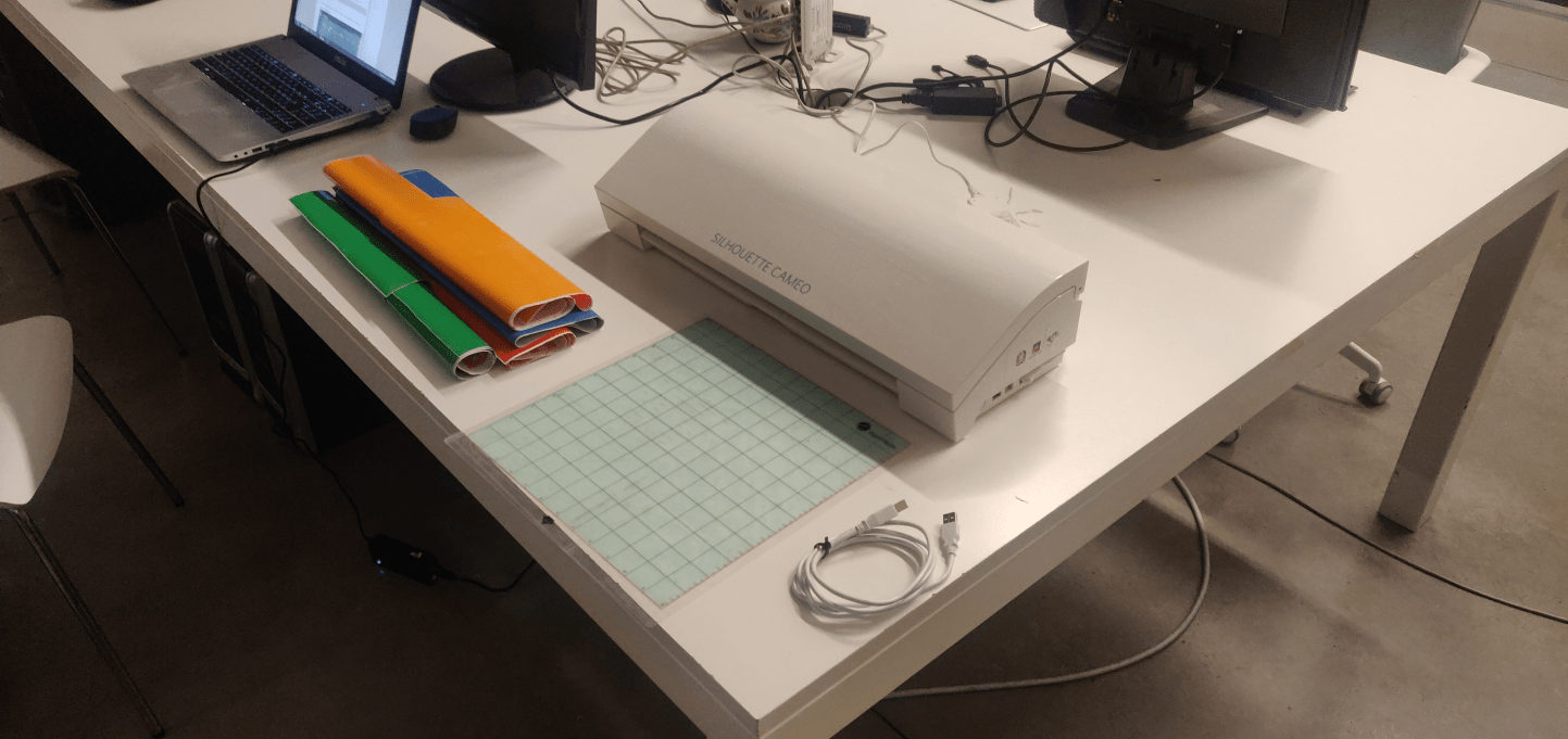
The first thing I did was to place the vinyl on top of the cutting surface provided and loaded the material into the machine.
Then I moved back to Inkscape and opened the plugin settings.
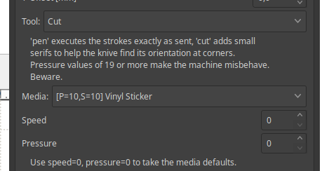
The inkscape-silhouette allows the user to set the speed and the strenght of the cut, and it does have some presets, including vinyl cutting.
To be more specific, the strenght was set to 10, and the speed was set to 10.
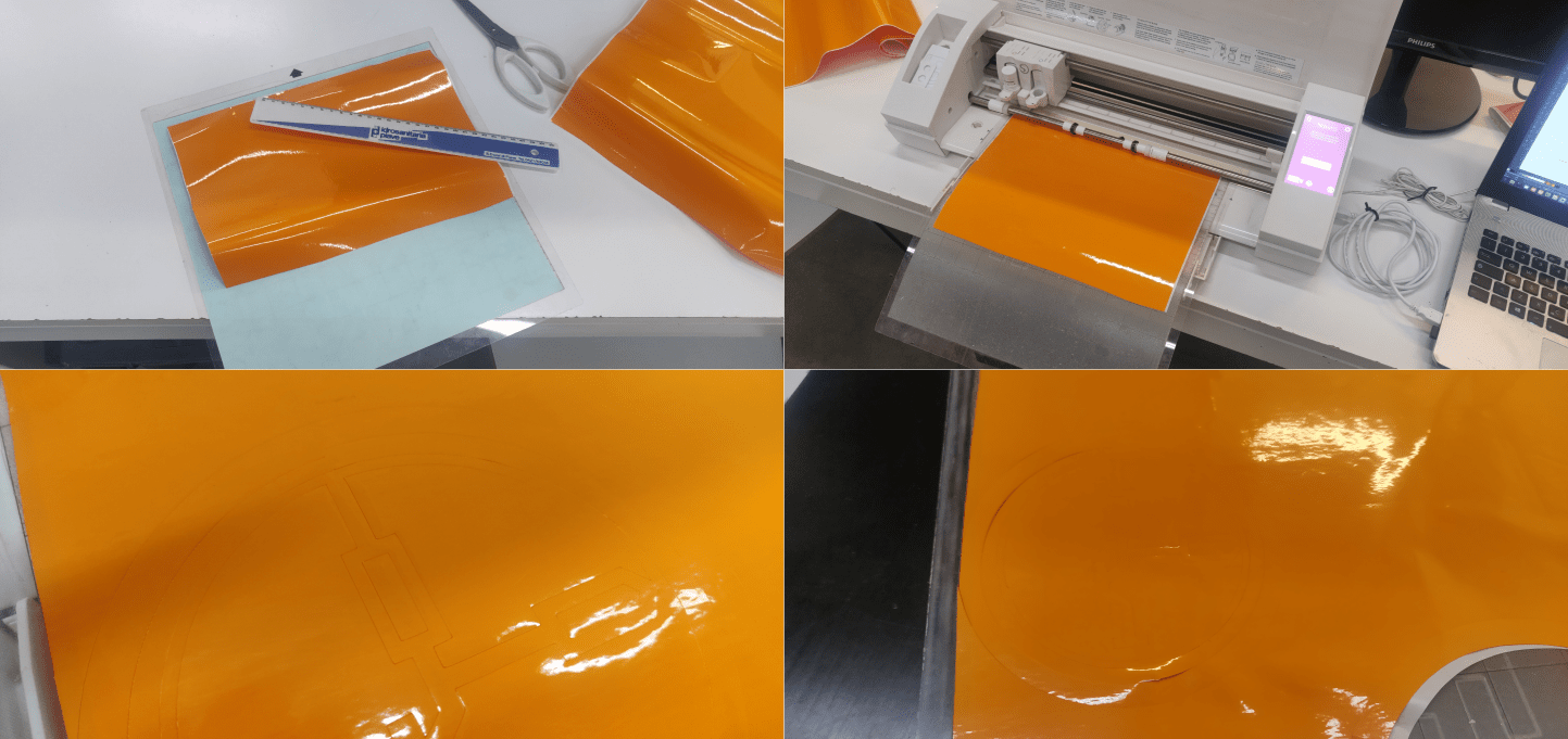
 So I clicked on “apply” and the machine started moving, producing me the graphic I wanted on my piece of vinyl.
 The speed/strenght settings were ok, but for some reason the gcode that the machine produced had an empty space of about 85 millimeters on top of my graphic. Even tweaking the settings of the plotter this issue kept going on.
In the end I just lowered a little the position of the vinyl and that fixed my problem (testing the machine with the official software this issue did not happen).
The speed/strenght settings were ok, but for some reason the gcode that the machine produced had an empty space of about 85 millimeters on top of my graphic. Even tweaking the settings of the plotter this issue kept going on.
In the end I just lowered a little the position of the vinyl and that fixed my problem (testing the machine with the official software this issue did not happen).
If cutting the material didn’t cause any issue, to peel it of was a little more troubled as a process, this was probably dued to the fact that the logo a choose was a little tricky to work with.
So, after a failed sticker I had to resend the job to the machine, and the second attempt was finally successful:
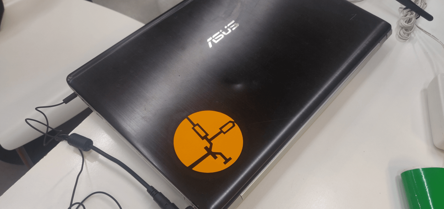
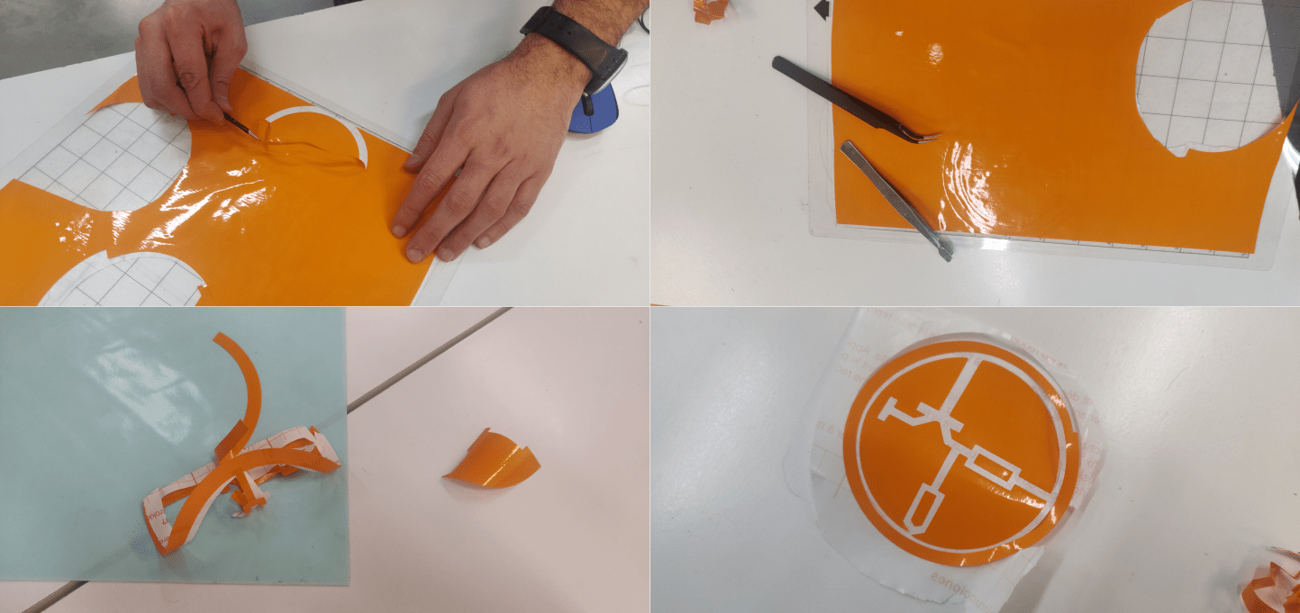 Now like any other extremist I’ve got my symbol to venerate and show around...
2 – Laser cutting
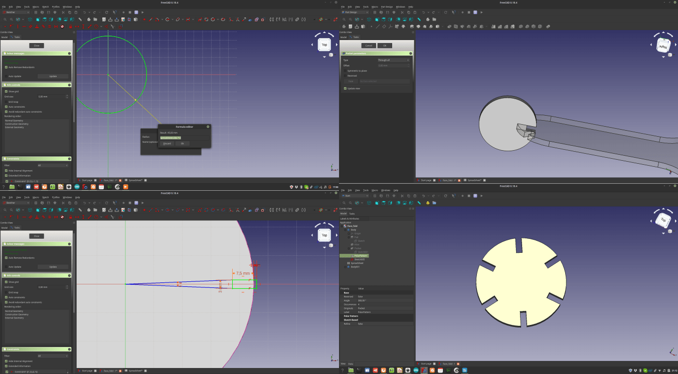
Next part of the computer controlled cutting work is to work with the lasercutter. The Crunchlab where I’m working from is equipped with a big (and stinky) laser machine. The first thing I did to work with this beauty was a series of geometries that I made to test the settings of the machines and the bending property of the materials I’ll be working with and the tolerance that I need to have an effective connection between the parts I’ll design later to make the construction kit
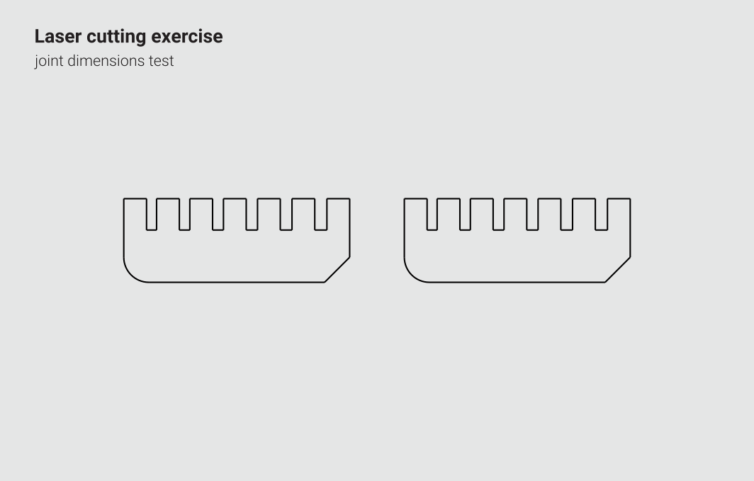
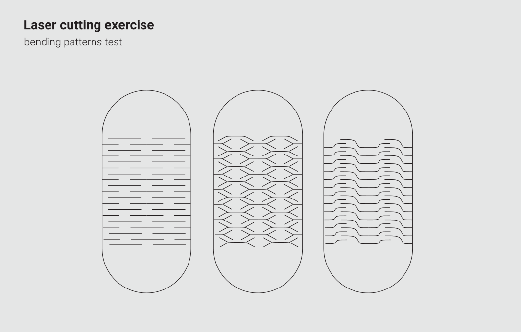
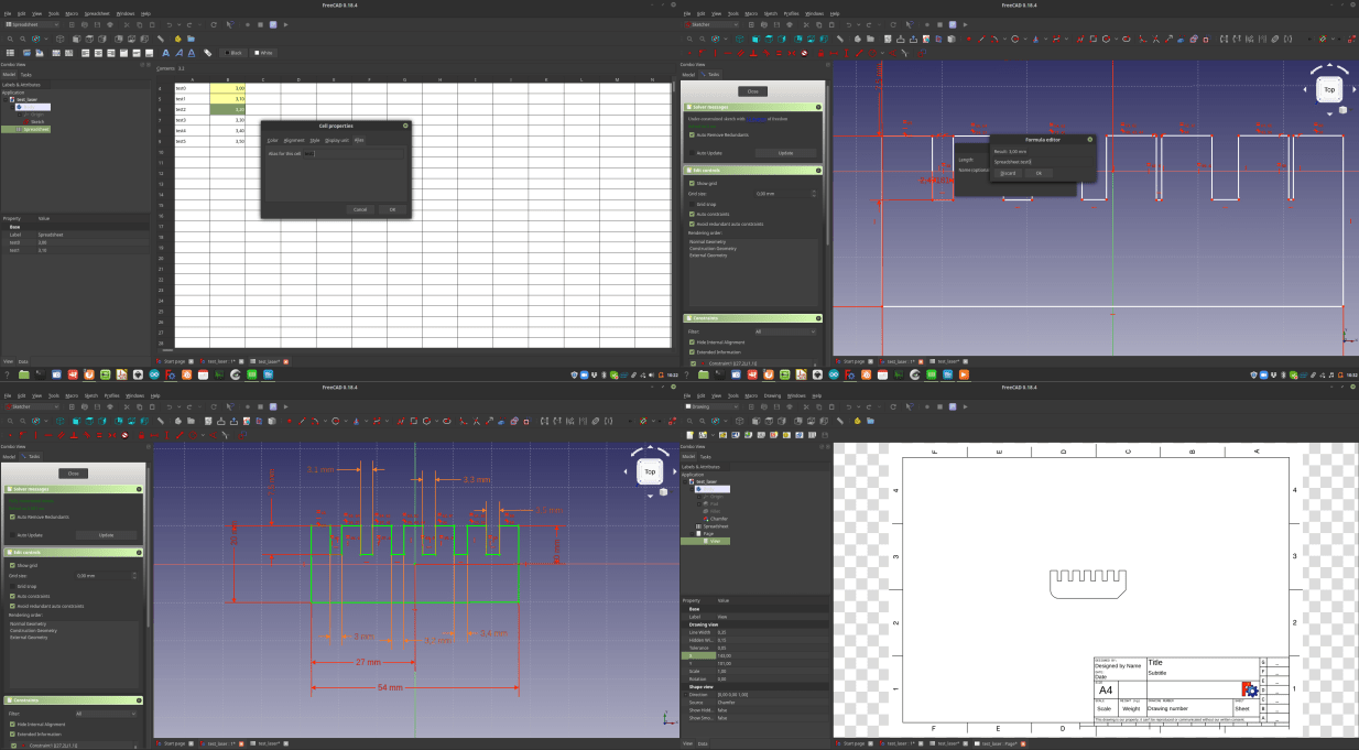
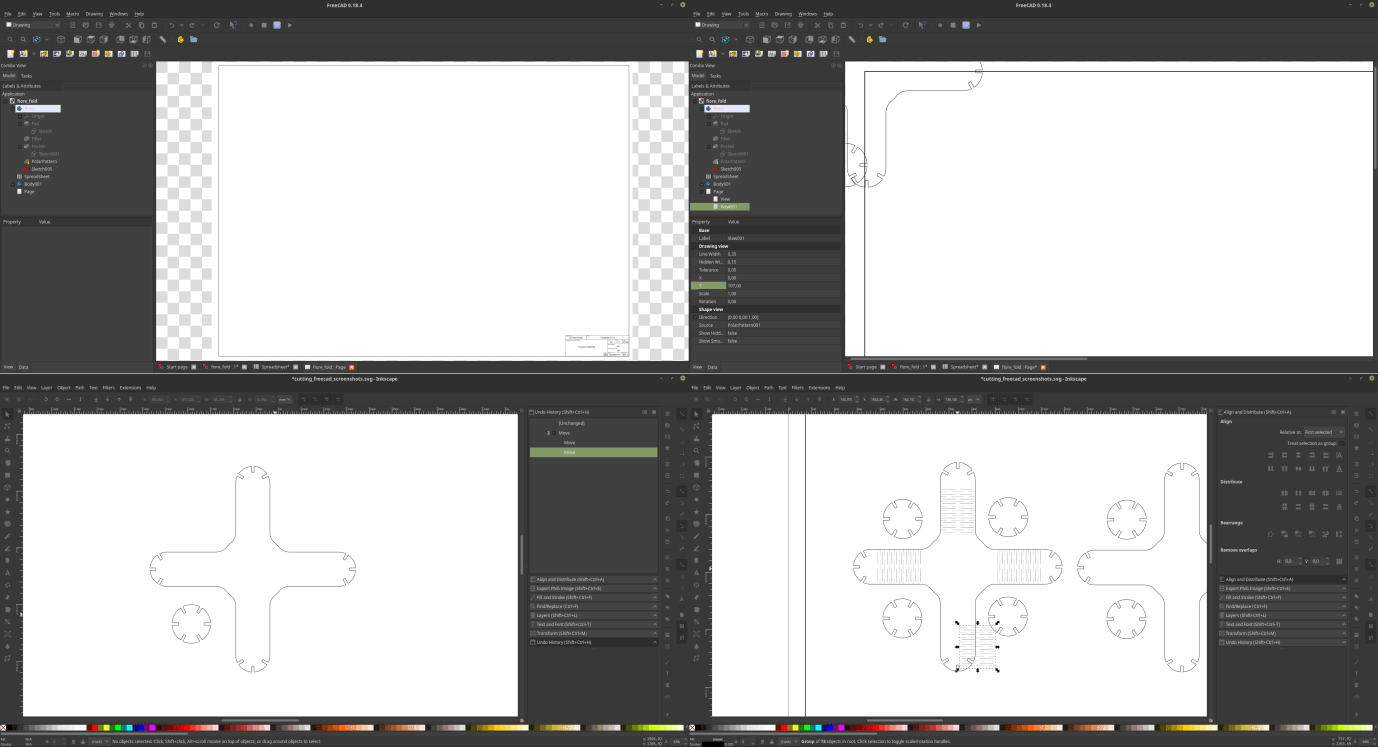
To reach those goals I used once again Freecad and Inkscape. In Freecad I worked with paramatric sketches that I connected with a spreadsheet where I placed all the dimensions that I’ll test. Once the spreadsheet was complete I modeled a set of very basic elements with some slits, using as constraints the data in the spreadsheet. Then I used the good old draw workbench to turn my models in 2D vector graphics and moved to Inkscape to add the bending patterns to my test-geometry.
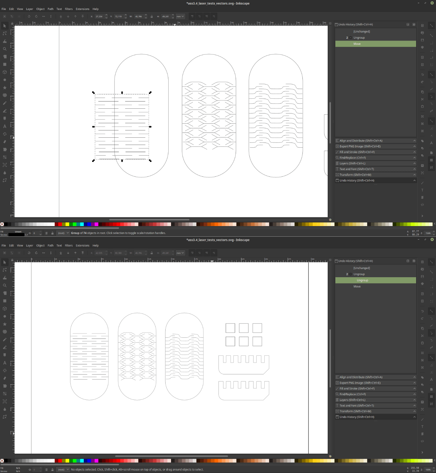
I found online here an old DXF/AI file (you’ll find an SVG version of it at the bottom of this report) that contains several patterns that I imported in my file and applied to my test-design.
At this point I was quite happy with my test file, and I finally started to work with the machine!
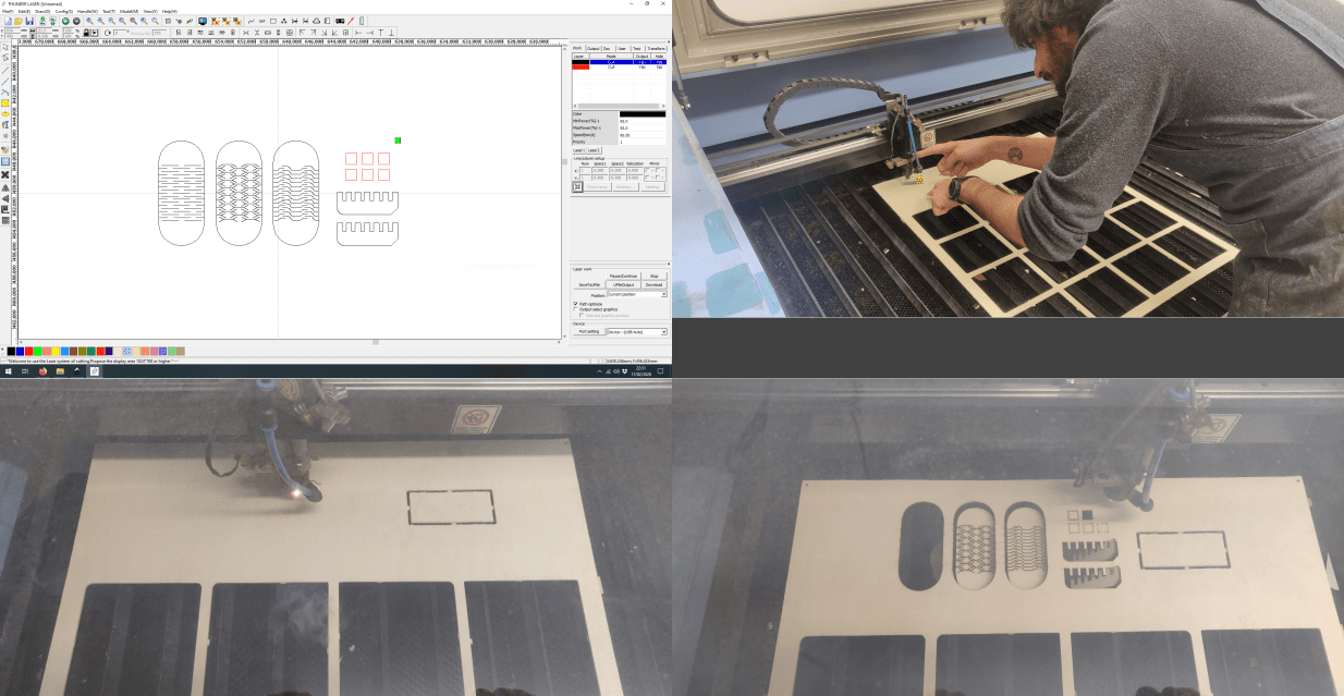
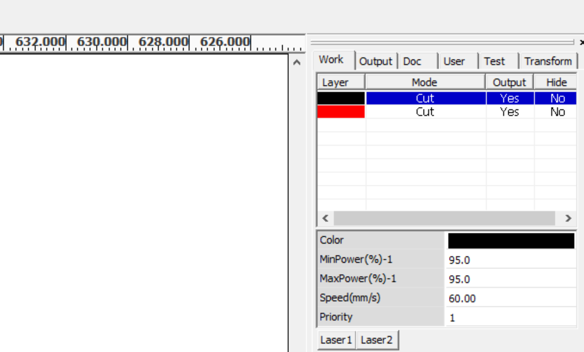
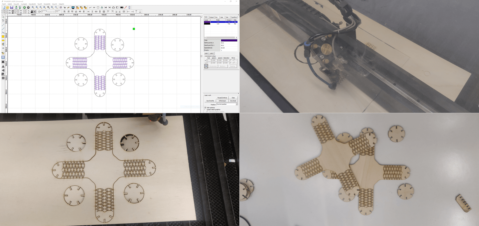
I started to work with the driver of the laser cutter, where I worked with the settings to make my first cut, (the vectors explained above plus a set of squares). The most important settings I tweaked were the power, that goes from 0 to 90%, and the speed of the machine, which is calculated in mm per second. In the Crunchlab there’s a book containing an archive of all the cuts done there. By consulting the archive I had some clues about what settings to use to cut my wood, and, to test how the machine works I also experimented a little with the settings. And then I exported the gcodes into an usb drive. Then I went to the machine itself. The first thing I did with the machine was to place some the material I’ll be working with on the plate of the printer, and focused the lens towards the top surface of my wooden sheet. Then I uploaded my gcodes into the machine’s drive and, after testing the position of the material I started to cut.
Once the work was done I exterminated the outputs of the machine. The most evident thing was the difference between the squares I cut with different settings, some of them where not even cut through, and the thickness of the lines in them were all different. Then I tested the bending patterns, and the most flexible was the crossed-shaped one. The last and more tricky thing was the joint. In fact the connection was way too loose even in the smallest version of them.
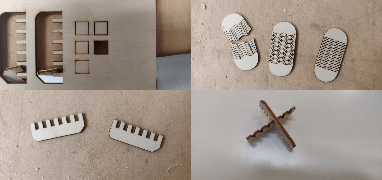
To solve this problem I first tried to fix it by tweaking the settings of the machine, increasing significantly the speed of the machine, but the connection was still way too loose. So I went back to FreeCAD, and by interacting with the spreadsheet I changed the dimension of the slits. Once this was done I did another cut, and this new version was finally successful.
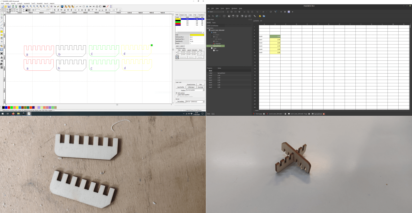
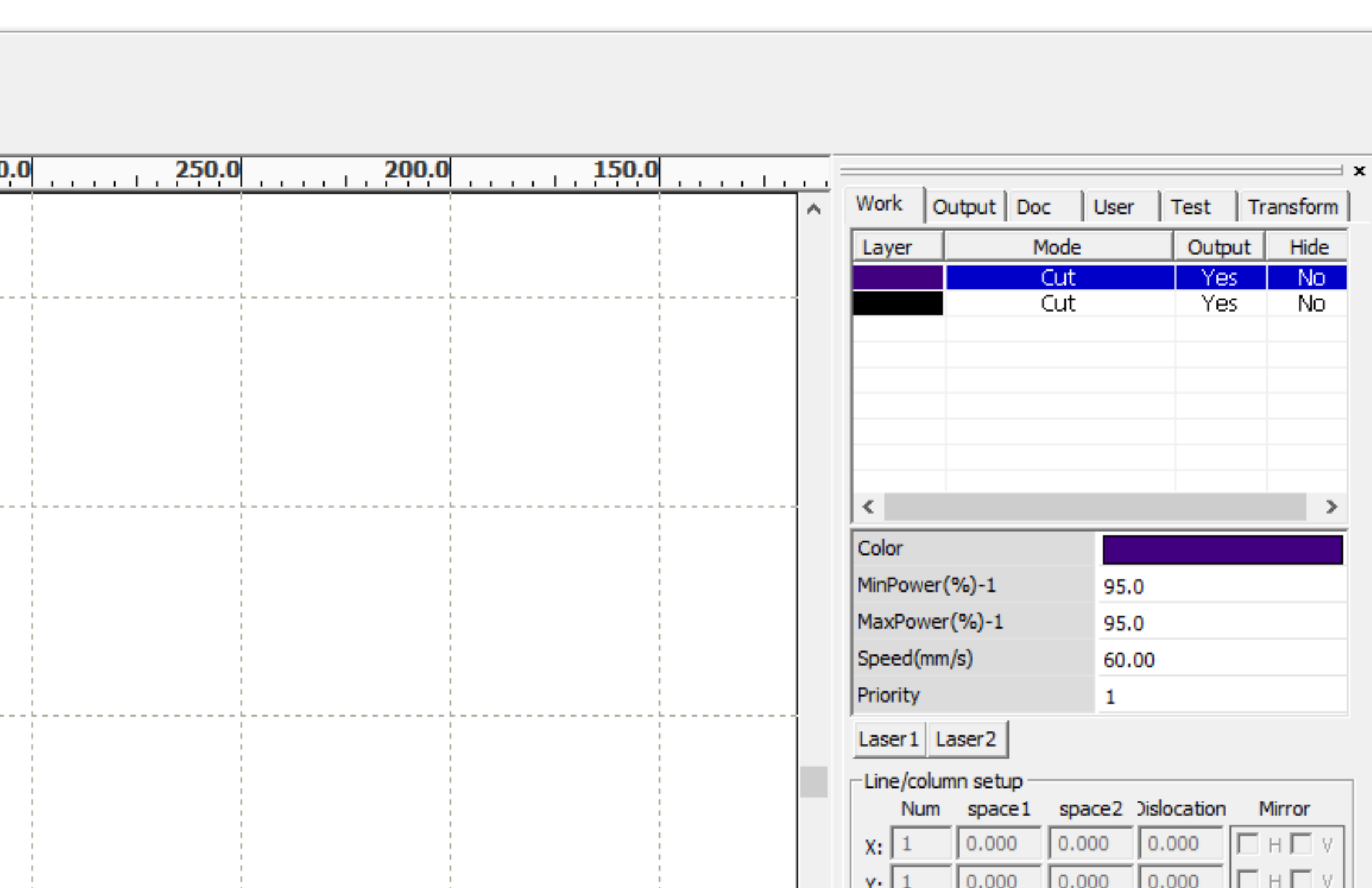
So, the setup of the machine that worked for this pieces used a power value of 95% of the machine power, and the machine was moving with a speed of 60 mm per second. The software allows you to set a coloe for each path, and to set speed and power for each color
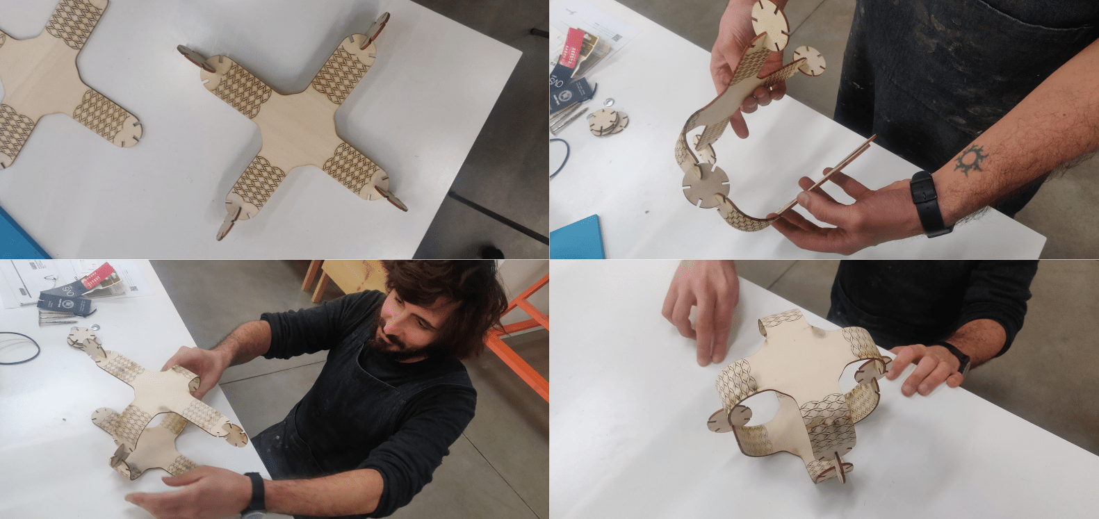
Next step was then to design the construction Kit that Neil requested. My idea was to design a kit based on some crosses with bendable arms that is possible to connect and generate various shapes.
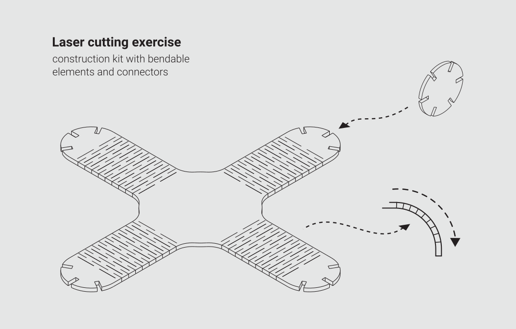
To do that I moved once again to FreeCAD and designed the pieces, using again a spreadsheet to interact with the parameters of the model, using the settings that I found out during the testing phase. So, I designed a cross element and a connector. Last step in CAD for this assignment was to turn this 3d model into an SVG and, in Inscape, to add the folding patterns
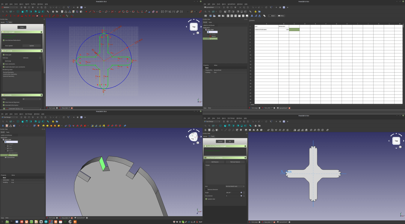
Once the vectors were done I came back to the driver and prepared the gcode for the machine. After my previous experience the cut of the pieces went quite smooth, and I finally had in my hands the pieces for my construction kit. once again the machine was set with a power percentual of 95%, and the speed was set to 60 mm per second
3 – Assembly
Last part of this assignment was to connect together all this parts. I knew that the joints and the bending was well tested and all, but I was still quite afraid of breaking the kit while putting it together. Anyway the process went well and the kit worked really well. Due to the lack of time I just made a set of 2 pieces, but it’s possible to make more and have the chance of putting them together in different configurations.
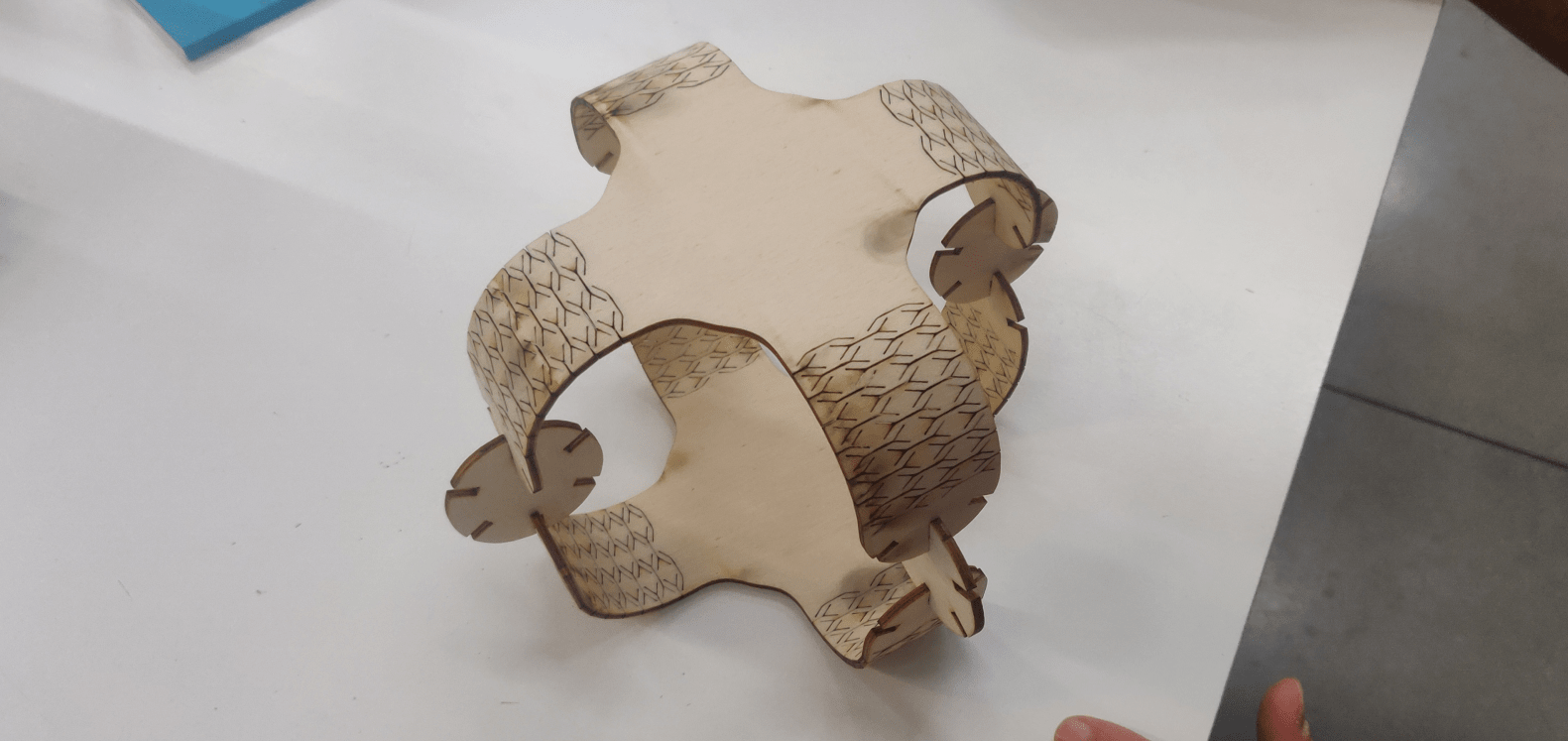
And that’s it, the kit works well and everything stays in place…
4 – source files
Here are all the source files for the Computer controlled cut assignment:
1 – vinyl cutter vectors
2 – laser test parametric 3d model
3 – laser test vectors
4 – bending patterns vectors
5 – construction kit parametric 3d model
6 – construction kit vectors
5 – Notes, takeaways and plans for the future
I had quite fun doing this assignment, but I have a few things that I would like to explore further in the future. First of all I really need to find out why the Inkscape plugin had that extra space in the cutter layout. Then I would like to explore in depth the possibility of engraving graphics on my designs. Last but not last, I would really like to produce more pieces of my construction kit to make more interesting configuration of the kit.