WEEK 11: output devices
Assignments
individual assignment
add an output device to a microcontroller board you've designed, and program it to do something
group assignment
HERE you can check what we did on this week group assignment
measure the power consumption of an output device
individual assignment
for this assignments i just measured de consumption on a dc motor using an arduino uno and an old L293D motorshield
first, before i start writing code i have to had the right library
from here you can get to know how to install that specific library
then i had to write some simple code on the arduino IDE using the motorshield library from adafruit
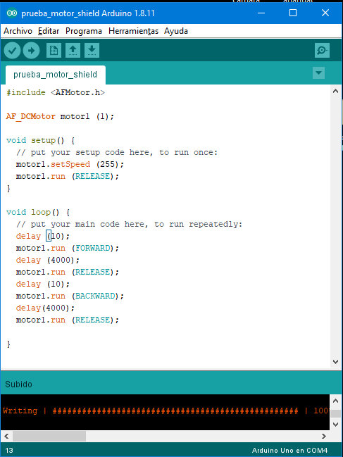 a screenshot on my code
i'ts really simple all it does is alternate between clockwise and counter-clockwise in 4 seconds intervals
then i just had to hook up the arduino and the shield together and that was pretty simple just had to align the pins on the arduino board and the motorshield board and then gently press them together
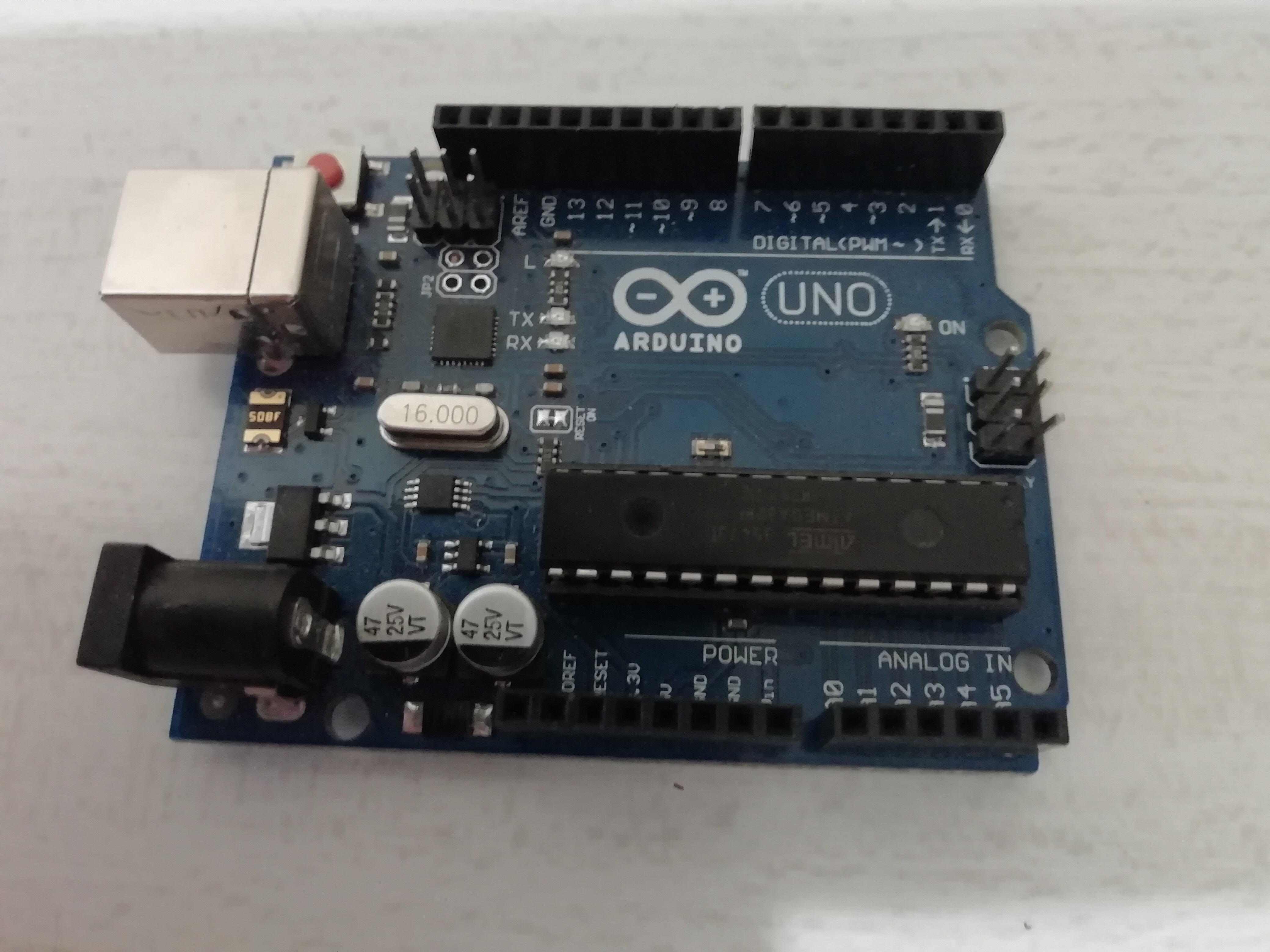 arduino uno board
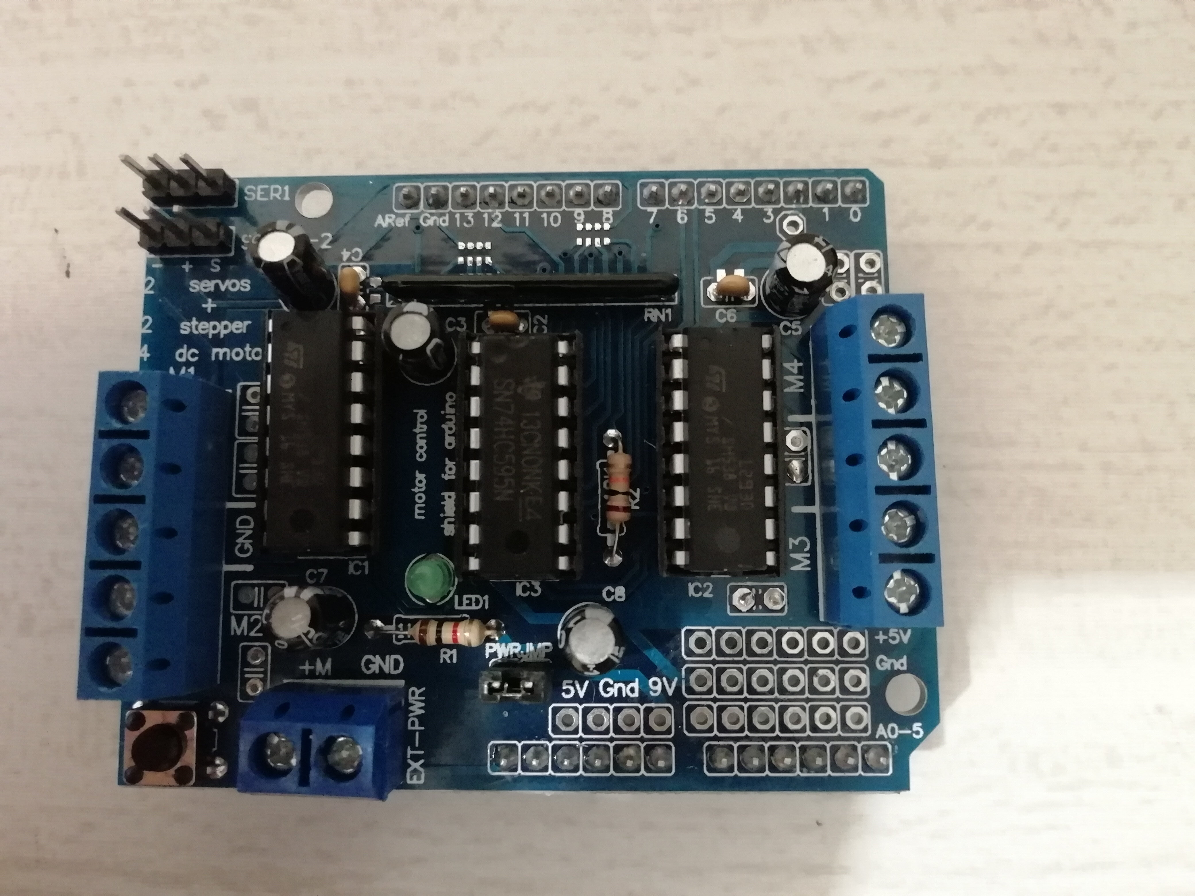 motorshield board
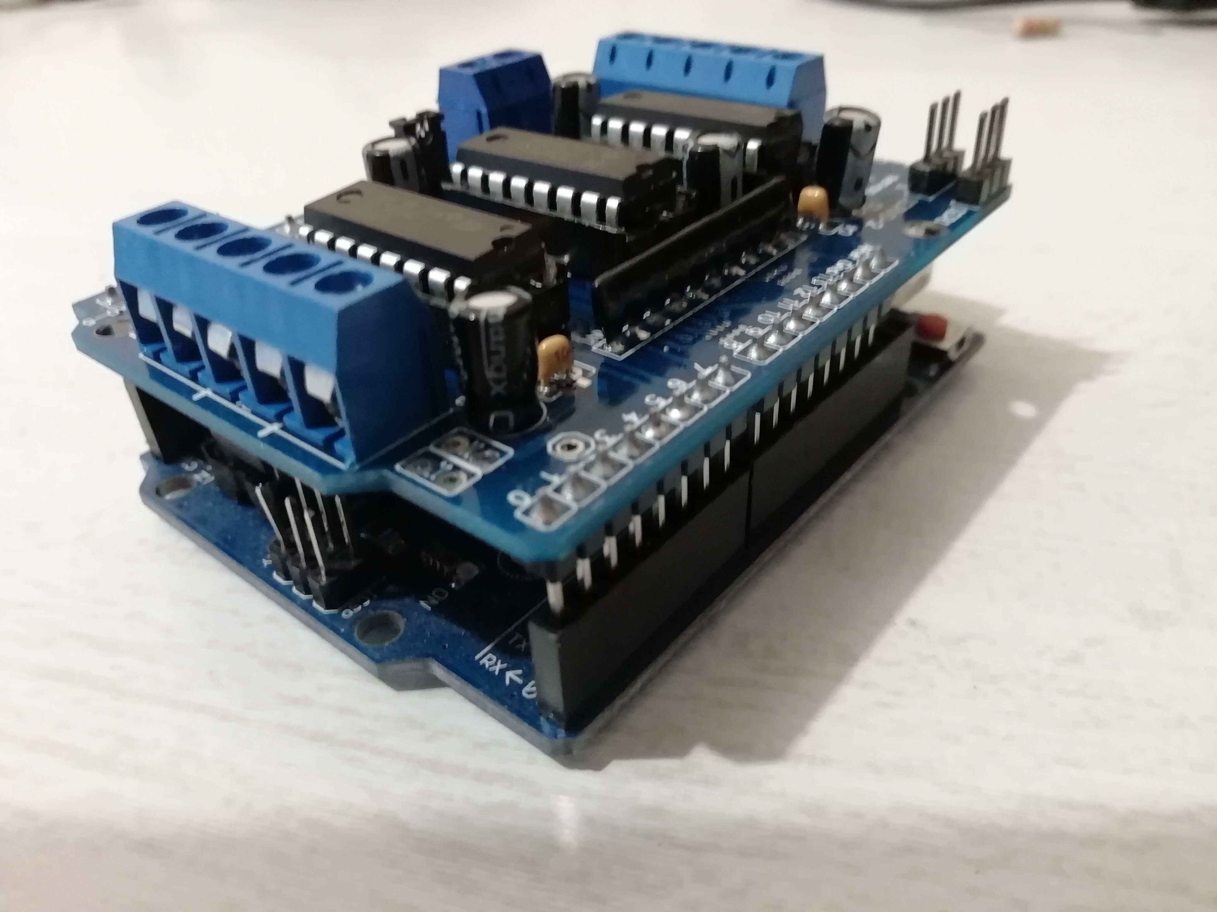 press them trying to not bend any ping and therefore messing up the board
in order to wire the motor you should know about the board and it's capabilities
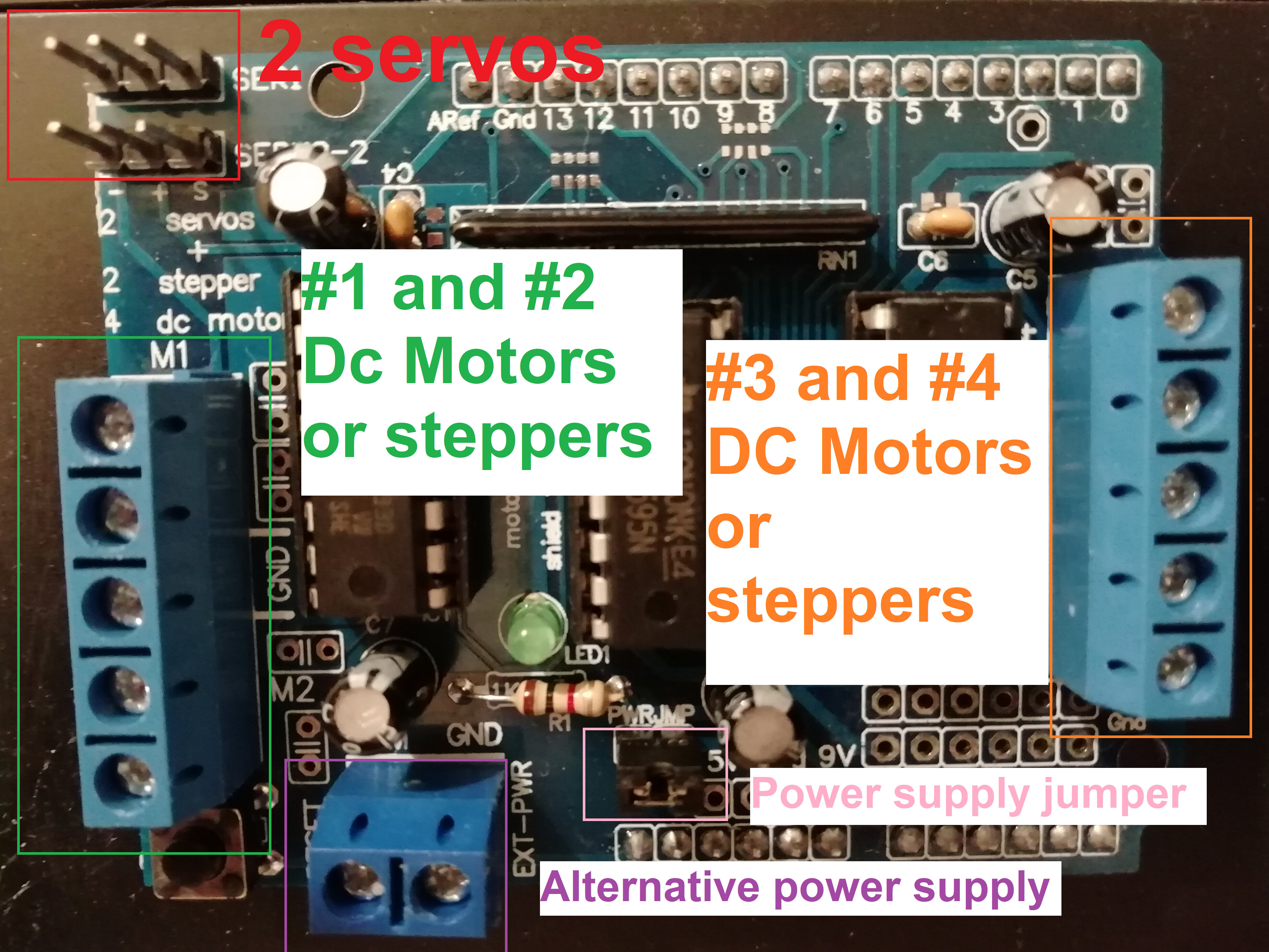 motorshield wiring
by default it will try to use the power from the usb or the power jack from the arduino board
but for motors you should always try to use alternative power supplies because arduino boards in general can only handle little currents and motors draw a lot of current depending on the torque and winding of the coils and such
in order to tell the L293D motorshield to handle power from outside the arduino board just remove de jumper on the picture abvove
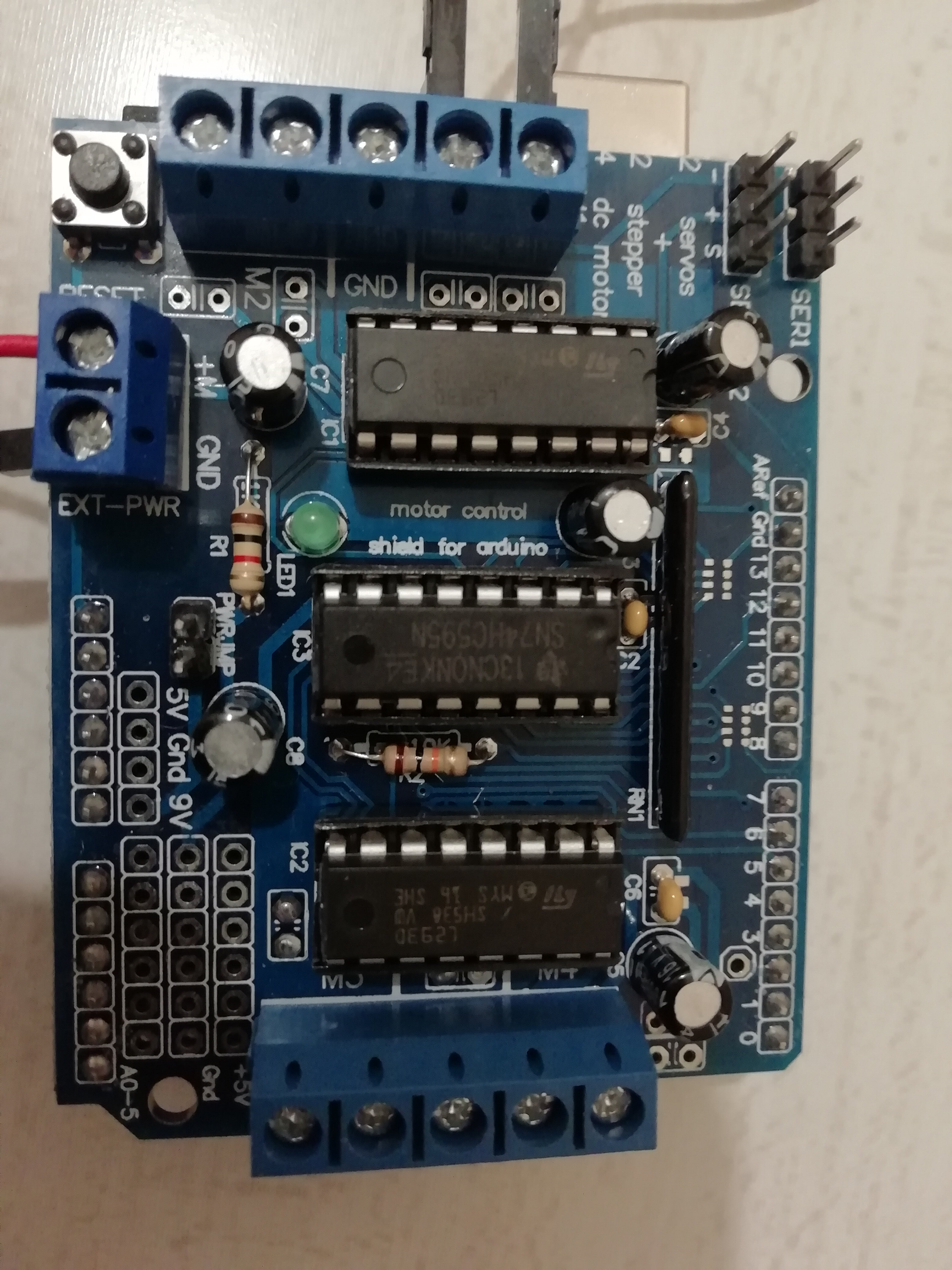 motorshield without the jumper
now, i had to conect the power supply and the motor to the shield
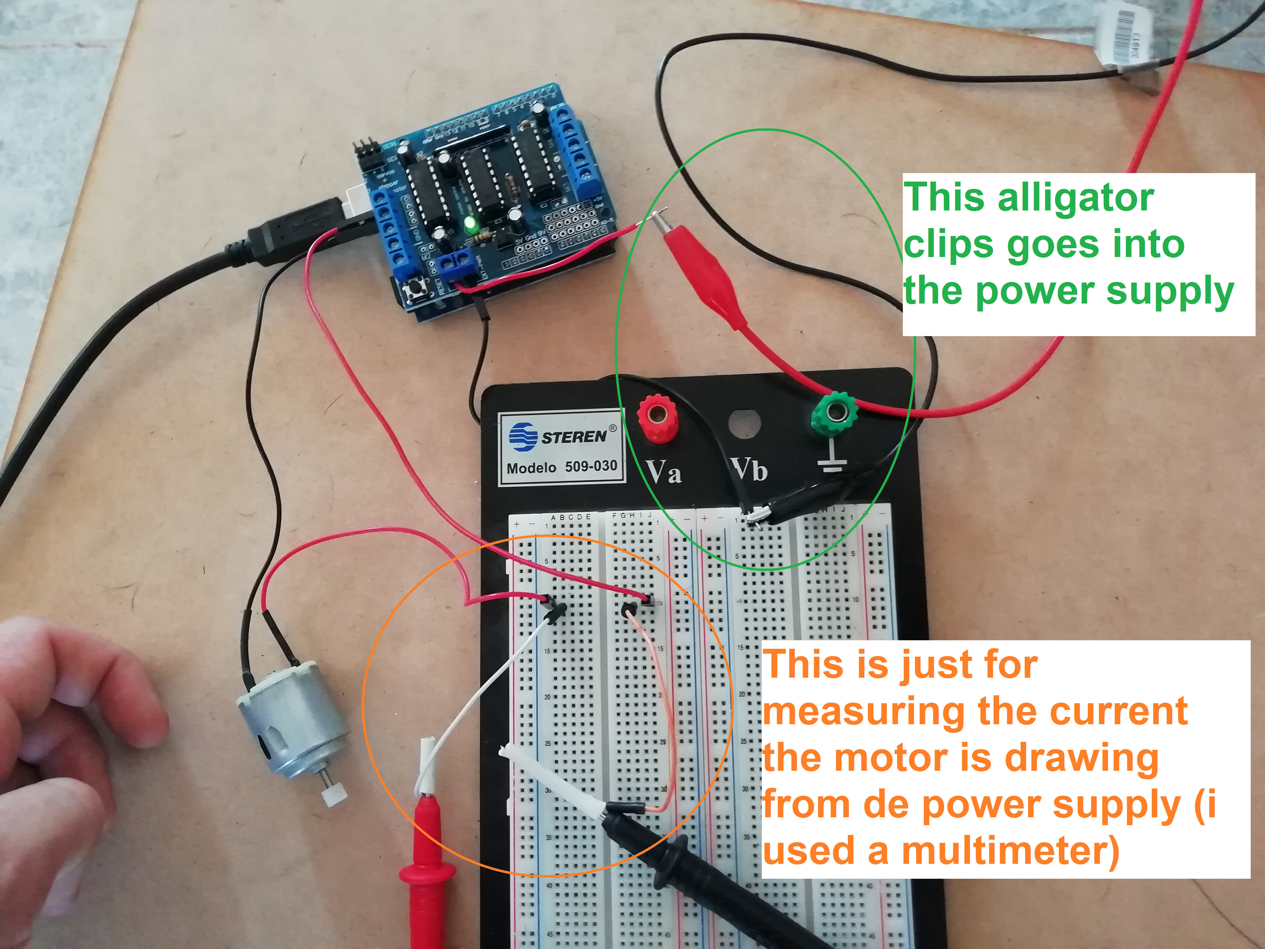 the motor wired to the shield and the power supply
i used an old protoboard and some jumper wires to conect all together
so, it is finally time to plug the arduino to the usb and the computer and upload the code
here you can have the code i used
once the code is uploaded and the power supply is powered on the motor started to spin and i had readings on the digital power supply display and in the multimeter
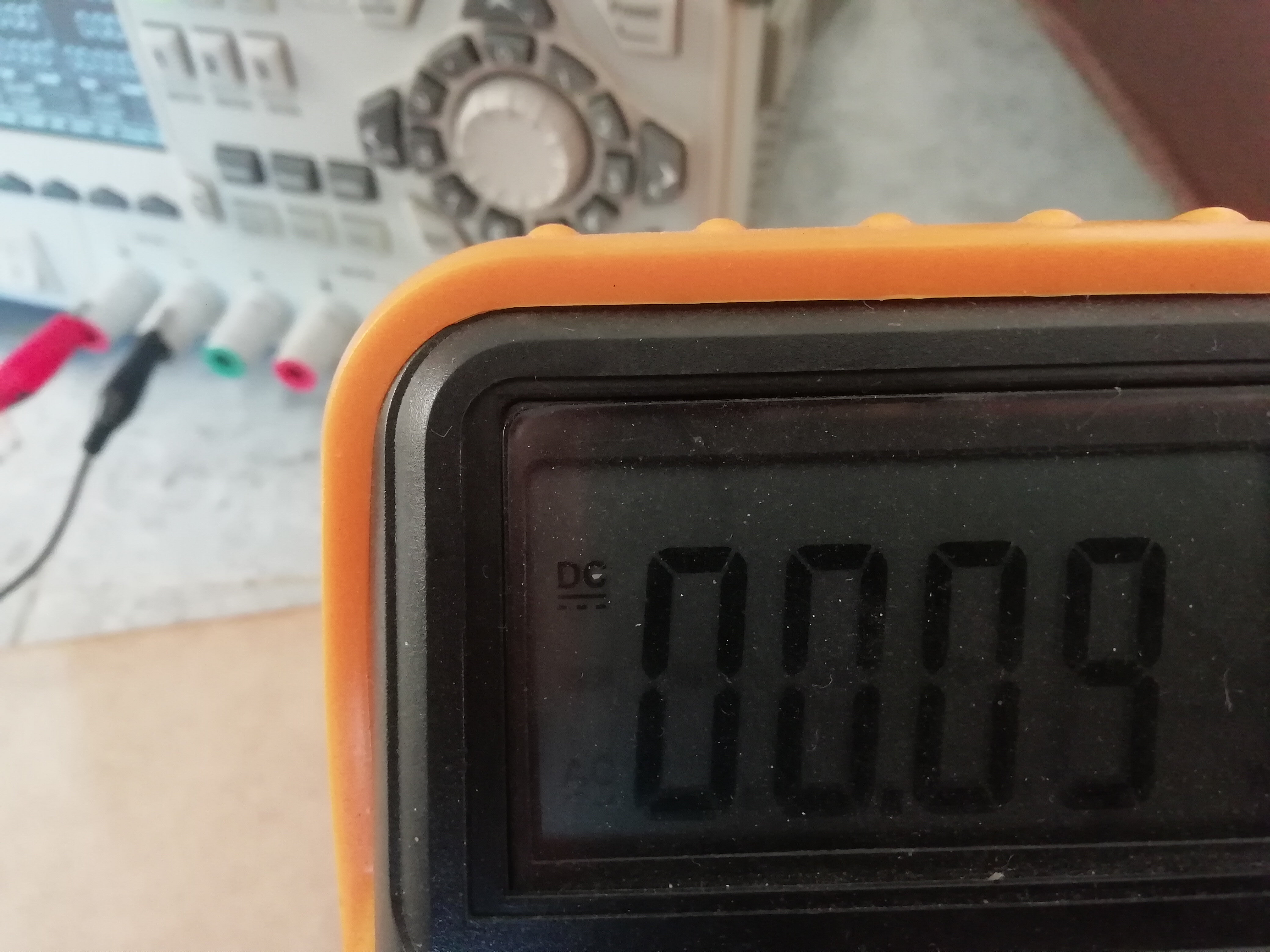 multimeter display showing the current the motor is drawing from the power supply
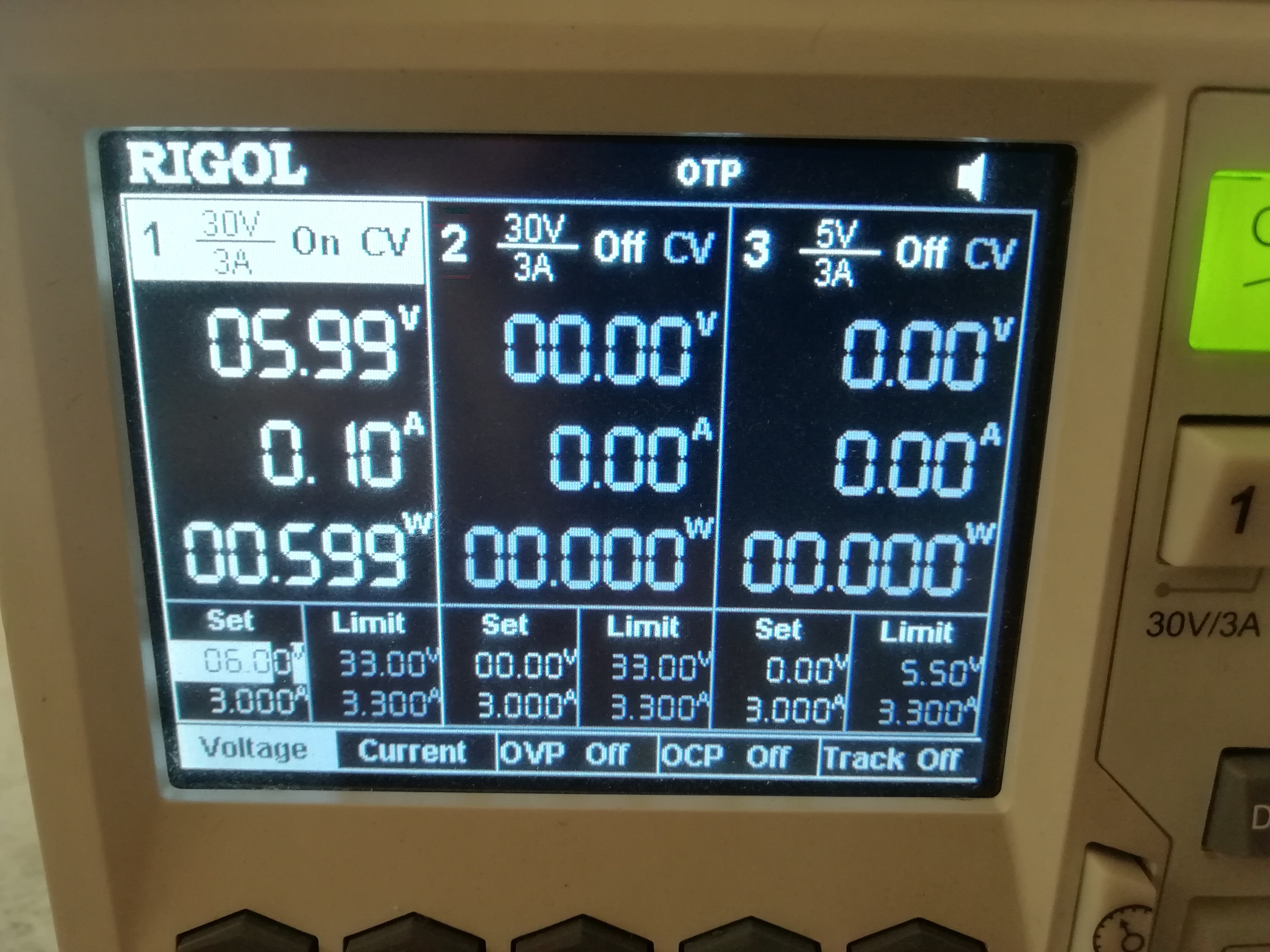 power supply display showing all the parameters
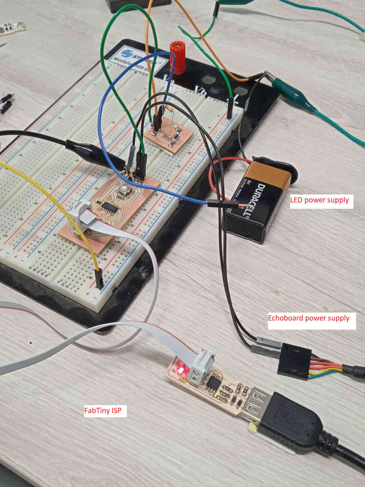
in my repo i will upload a video showing my circuit working
video hosted on my gitlab repoas well as a link to the same video hosted on my youtube chanel
video on youtubereferences
youtube video on using the motorshield
link on how to install the adafruit library
Update 06/07/21
Group assignment
Here you can check the Group assignment on this week
Update 15/07/21
Individual Assignment Redo
I know i still need some polishing in my electronic designer skills.
I'm still learning tips and tricks everyday.
Echoboard v2.0 and output board
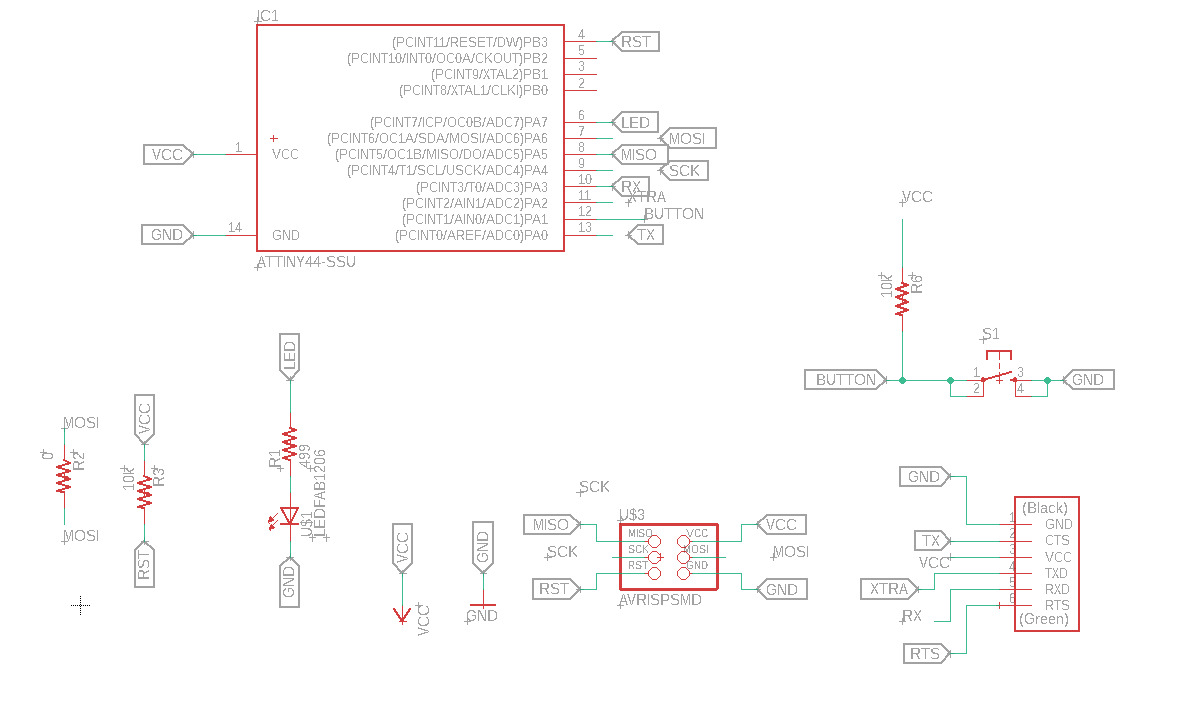
screnshot on the echoboard2.0 schematic
And i already have an Attiny45 echoboard
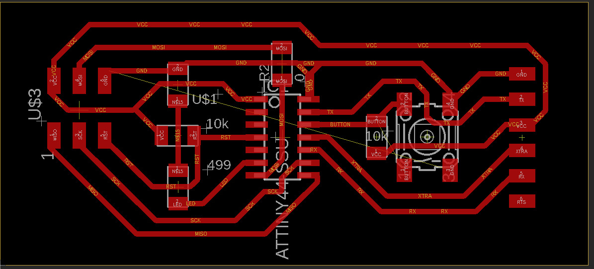
screnshot on the echoboard2.0 board
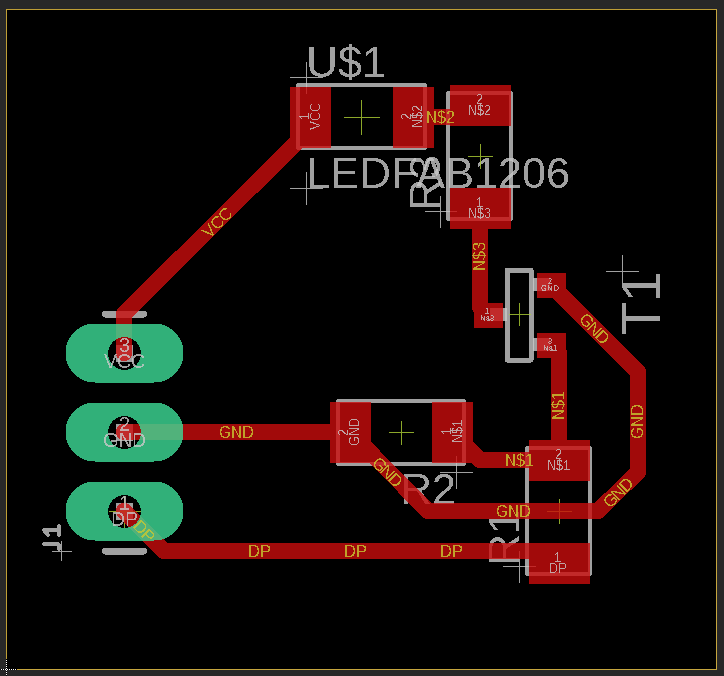
Screenshot on the output board.brd
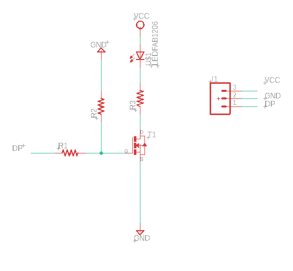
Screenshot on the output board.sch
Instead of the LED i could have a relay or directly a small DC motor.
but i don't want to waste anymore of the fab's inventory.
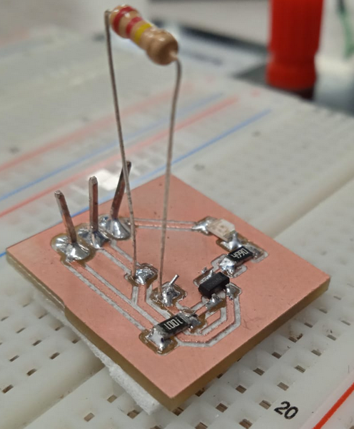
picture on the output board components
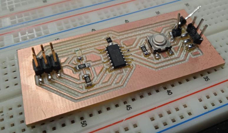
picture on the echoboard2.0 components
i know this is is just painful to see.
i forgot to replace the SMD version of the FTDI conector block in eagle for one that was THT
this is just the code of the button to turn on the LED board