Computer Controlled Machining
group assignment
test runout, alignment, speeds, feeds, and toolpaths for your machine
individual assignment
make (design+mill+assemble) something big
Update 06/07/21
Group assignment
Here you can check the group assignment on CAM
individual assignment
as always the links are at the end of the assignemnt (dxf,gcode,native files)
first i will like to apologise for pushing all my week update at last minute again.
now, i will divide this category into three aspects
CAD
For this part rather than using one modeling tool i chose to use two insted firs the actual model i did it on solidworks 'cause it's just easier for me to quickly change a drawing dimension or redraw from sratch all over again. then when i was satisfied with the result i made a render of it
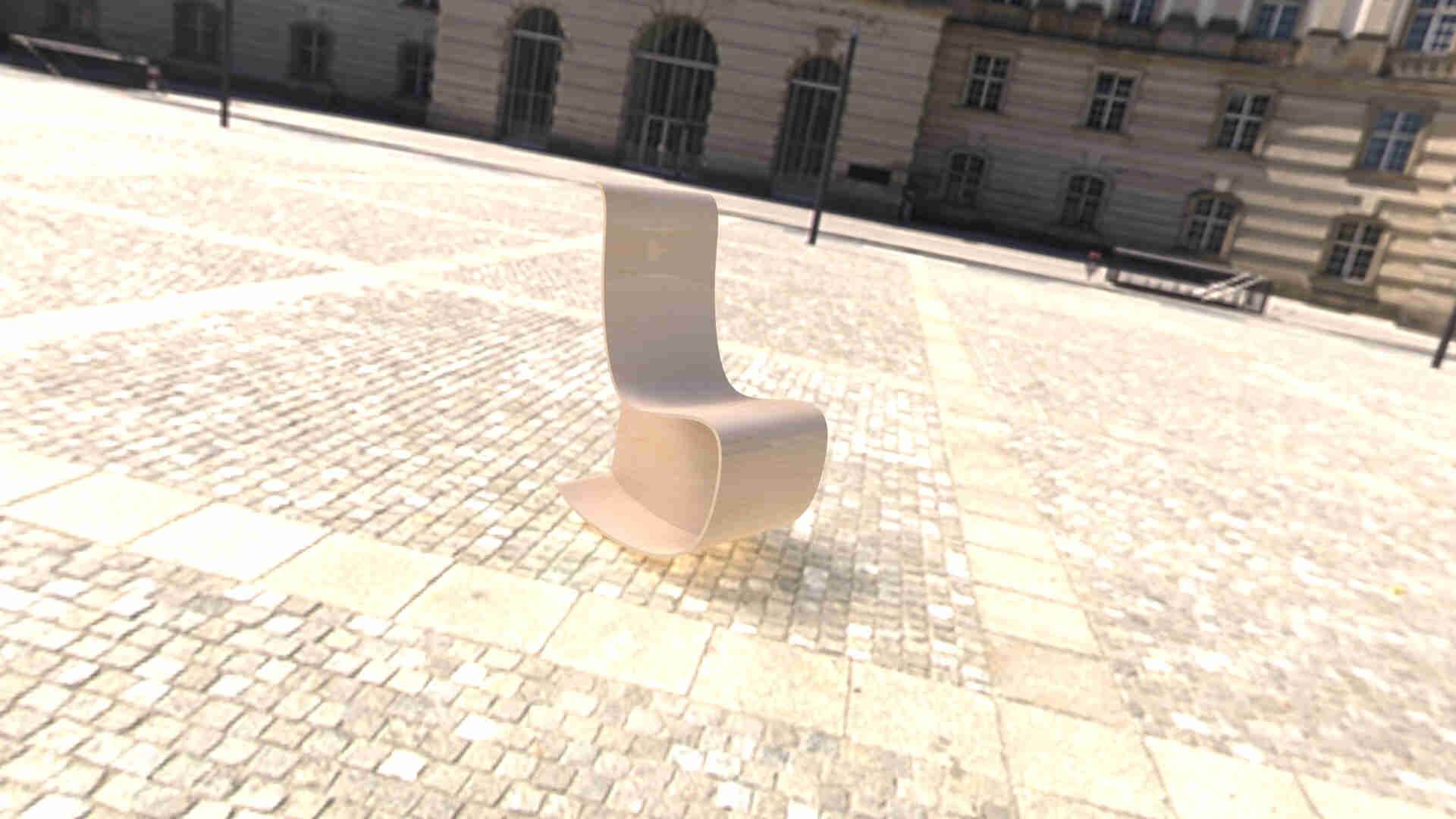 this was my renderized model on solidworks
then i saved it as low quality stl and imported on rhino 5 that i'm already learning how to use in order to transform it a little bit to extract the unrolled surface to project it into a 2D plane and import it into the "CAM" software
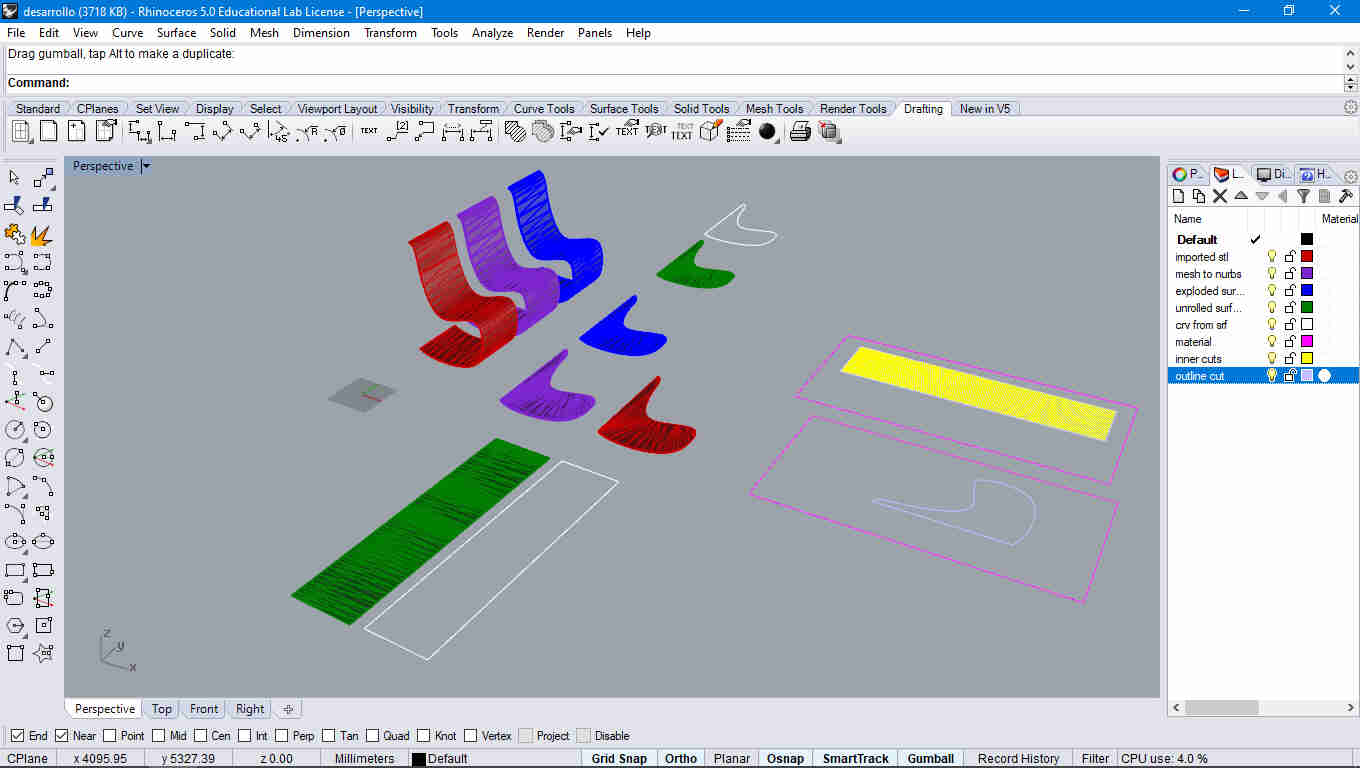 this was my rhino file here i detailed the comands on the layers
soon i'll be hosting all my files into the repo but first i'll have to compress them and push them
CAM
before i start to describe what i did on the "CAM" software i'd like to mention i did a 3D printing in this assignment to test if it was usable, obviusly i had to scale it down in order to fit into the ultimaker printable volume
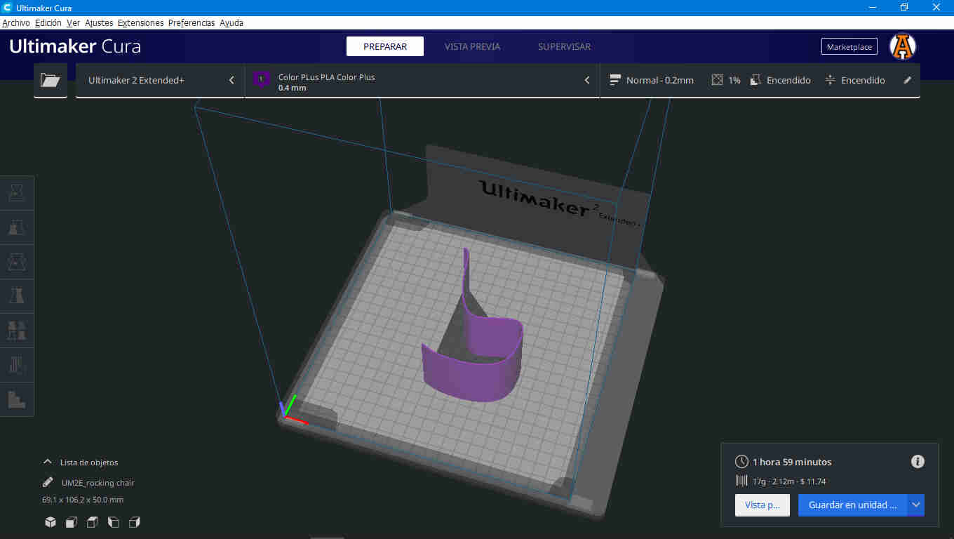 this was the model imported into cura after scale it down and orienting it in a printable position
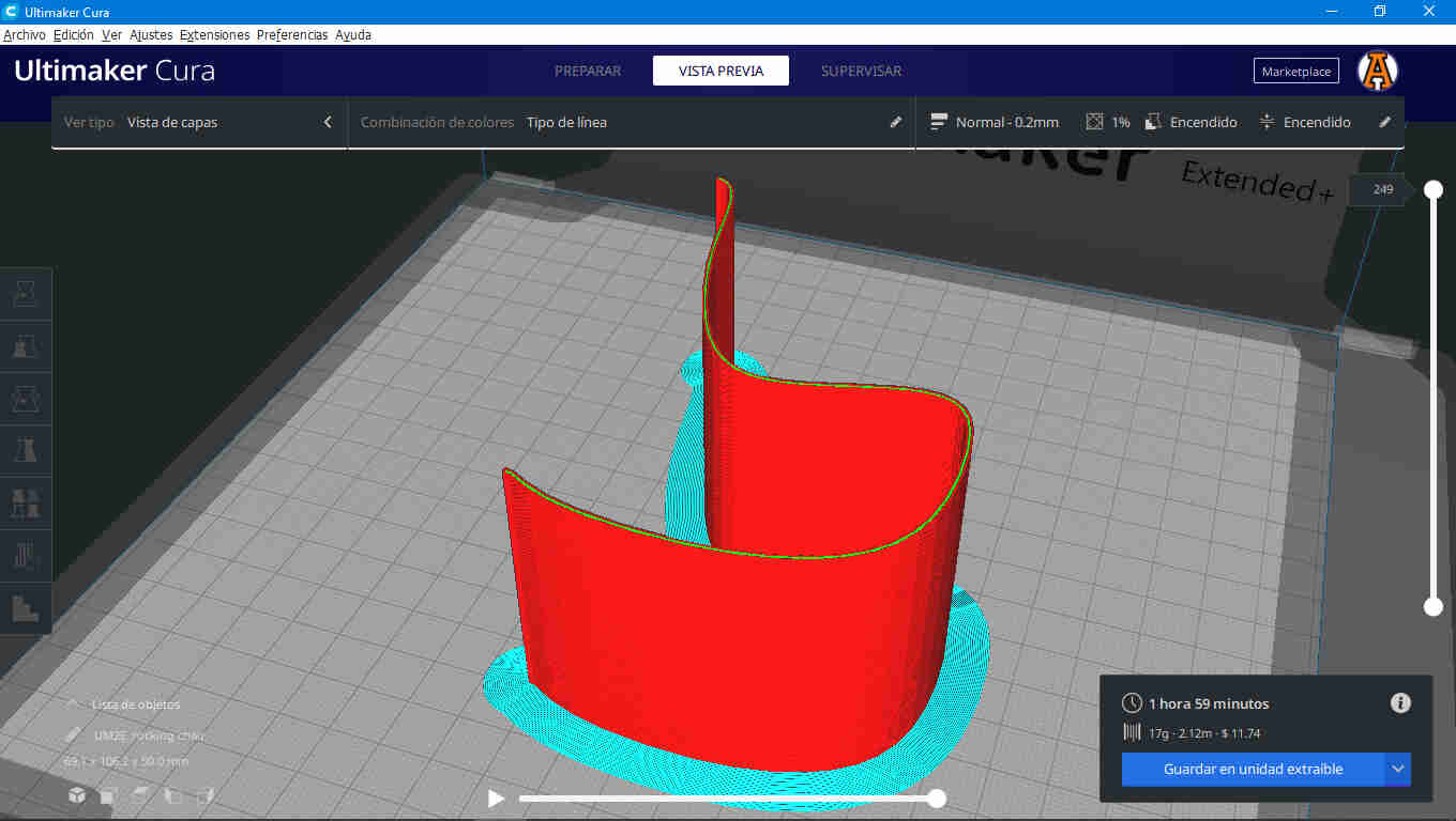 this was the model imported into cura after slicing it
after an hour of printing i had the prototype and i'm pretty stisfied with the result and i think the CAD is ready for machining
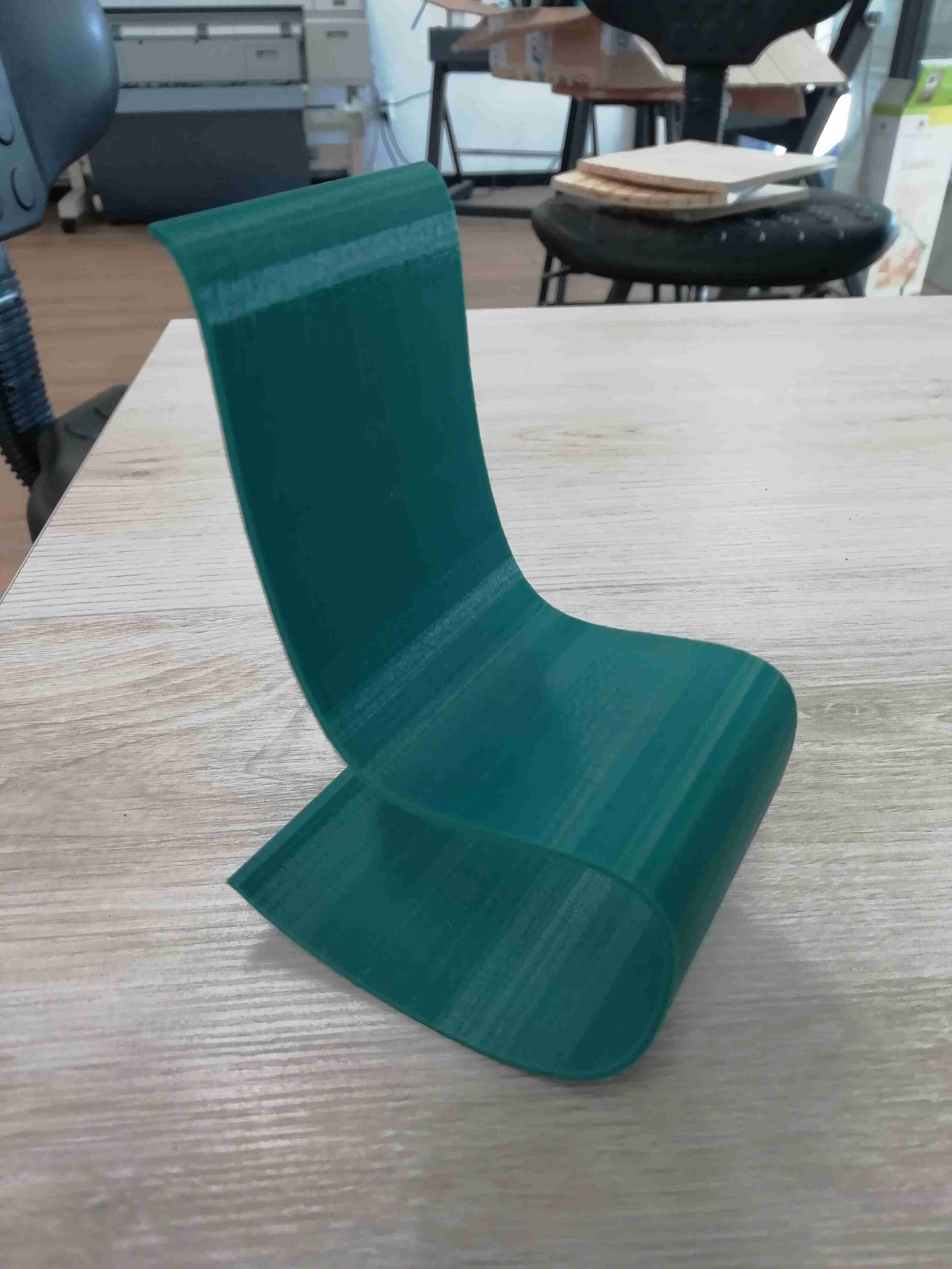 my prototype
so, ill be hosting this too
now. it is time to describe what i did this week on the "CAM" software.
and notice that all this time i have used "CAM", that's because Vcarve is not only a postprocessor to a lot of routers but also have CAD capabilities pretty much like camworks in solidworks or rhinoCAM for rhino but this are plugins you'll have to buy separetly in order to make them work in those enviroments
Also, Vcarve pro have a free trial version wich allows you to use all the operations it can perform but you can not extract the G-code from it unless you upgrade to the full version.
although Vcarve is a pretty powerfull CAD tool it's kind of tricky to make 3D models in it.
i think Vcarve pro is defenitly a great choice for makers that can not afford high spectrum CAD tools like AutoCAD,Solidworks, Rhino, sketch up where a single licence can be too much to start with.
that's why i used solidworks for modeling,rhino to translate ir into 2D shapes, and finally Vcarve pro for postprocesing
here i'll try my best to explain all i know about Vcarve pro and how to use it properly
Materials and origins
as soon as you open a new file inside Vcarve pro you'll have on the left side on the window a tab asking you the dimension,units,the location of the origin (on machine bed or material surface) this may change according to the machine on your lab
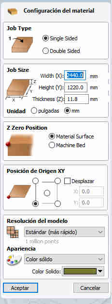 this were my settings for my material
CAD Tools
after you click on the ok button on the bottom of the tab the drawing tab will be displayed on the window also on the left side of the vcarve window
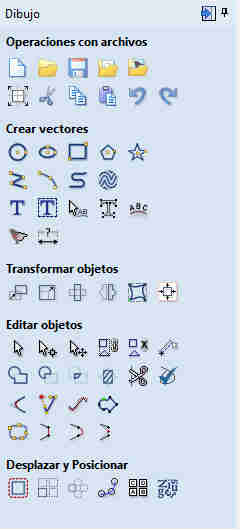 drawing tab
from here you can draw basic shapes circles,elipses, rectangles, poligons, the transformation section with move,scale,rotate mirror and such
the edition section were you can make boolean operations,trim, join, chamfers and more options
and lastly a section dedicated on position and displacement of object like rectangular arrays, polar arrays, offseting a curve and nesting operations
under all of that if you are managing diferent types of objects you'll like to make some layers on your work on the bottom left you'll find the layers tab and to change the object into that layer you only have to right click it and then move to each layer also you can block and hide the layer like rhino or autocad does
CAM Tools
once the drawing stage has ended you'll have to make toolpaths for your cutting operations that's done on the right side of the vcarve window jus click on a toolpath button
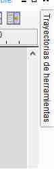 toolpath button
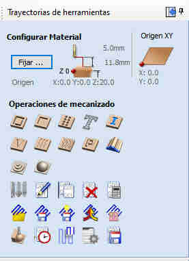
then vcarve will show you all the toolpaths you can create
like standard cuts,sockets,raster operations,sketching texts, 3D texts using V-bits 3D rough finish and 3D finish machining
 toolpath tab
Custom Tools
also vcarve pro comes with standard sizes of common imperial and metric tools, but quickly you'll want to create your own this may change according to your lab but roughly you'll have to calculate the RPM's of the spindle,feed rate plunge rate overstep and such. better ask your instructor about how to calculate that
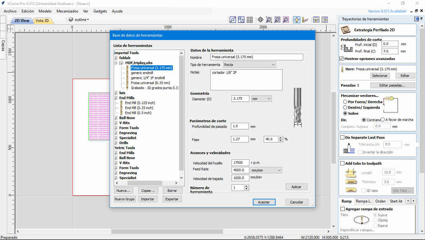 this is a standard endmill cutter used in our lab
Simulation
after you create your first toolpath vcarve will show you a breif animation of how it could look after cutting with those settings.
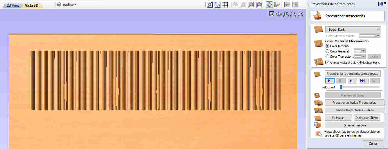 this is the test file on the simulation
Merging toolpaths
if you have diferent toolpaths using the same cutter you can merge them into one single toolpath (this will saves you a lot of time uploading a new file and running it after the last one ended.
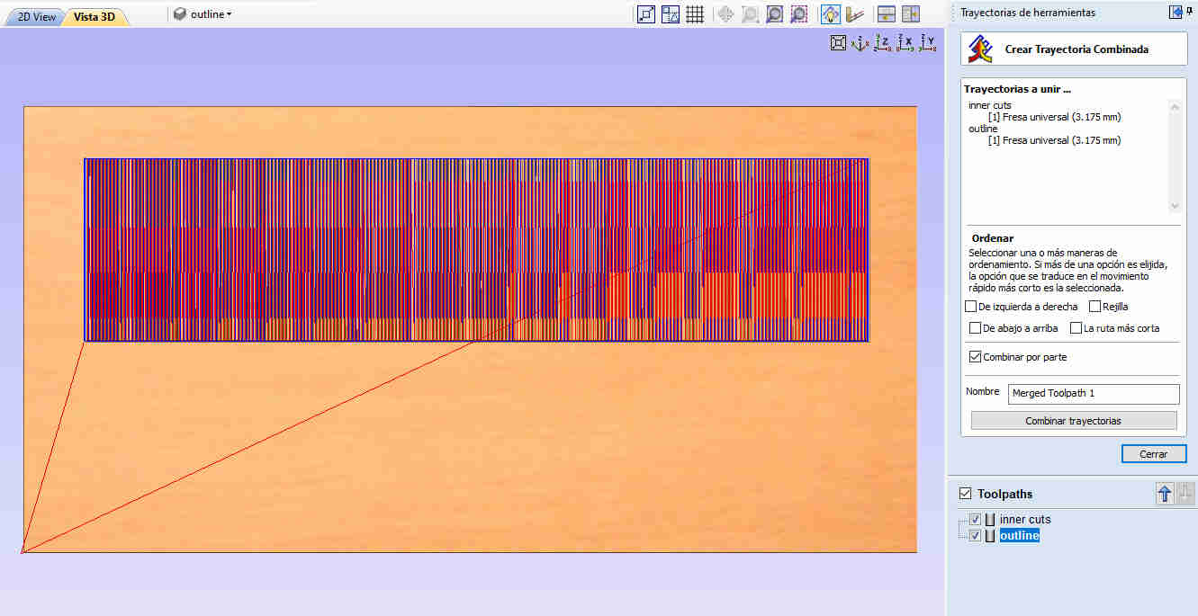 merging toolpaths
Extracting G-code
at the end you'll need to create a g-code file to send it to your machine
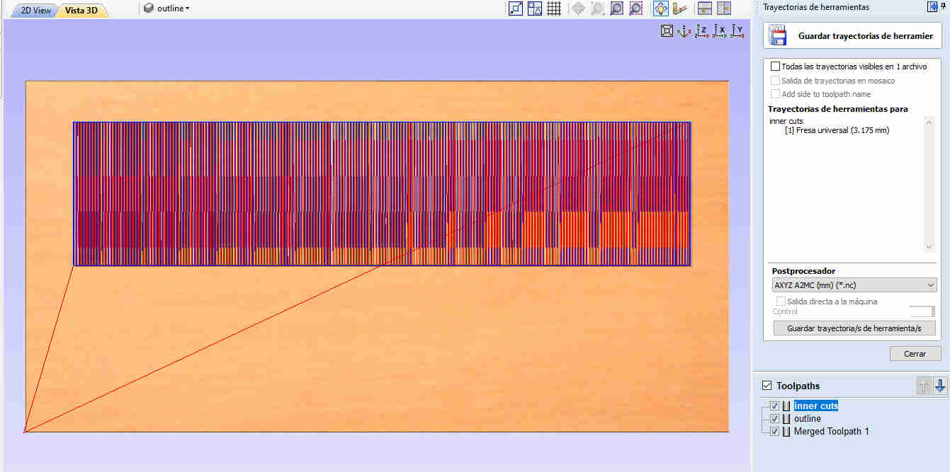 Here you can select what kind of g-code you want according to the machine in your lab
There are tons of machines listed here. better ask your instructor if vcarve support the machines in your lab
here's a silent tutorial i made about this topic
after all that you'll end up with a g-code ready to upload into your machine
I used a software called A2MC app manager to upload my files into the router
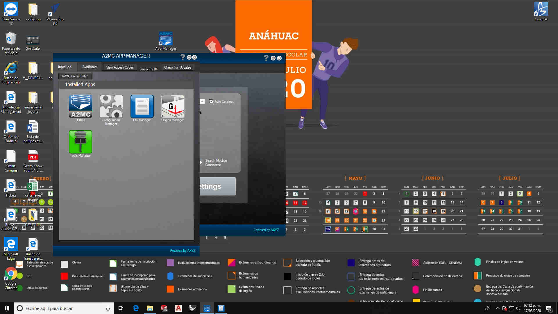 this is how it looks the software
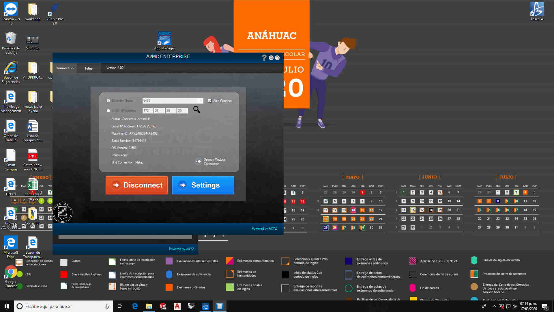 then i just selected File manager app and it showed a window for stablishing a conection
in order to upload my files i have to stablish a LAN conection to the machine and manually select a folder and upload the files into the machine's files folder
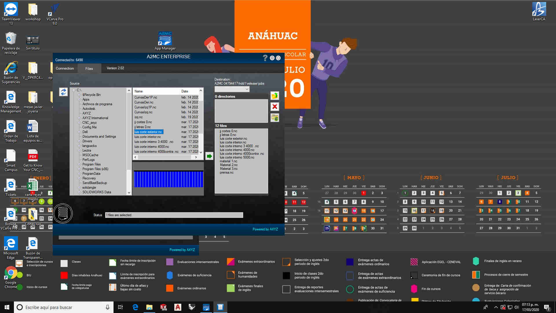 then i just located the folder inside my PC where i had my files to upload them
this is where thins get's interesting. i had help from ivan hernandez my fabacademy instructor. for the characterization of the tools in our FABLAB
but i had a few complications
First you have to turn on your machine and stablish the LAN conection in order to upload the files i just made. then you have to place the material we are not using the vacuum table to secure it to the machine so i have to clamp it down to fix it in position.
Then i have to place the cutter in the spindle
after that i had to make a XY origin so i had where to start
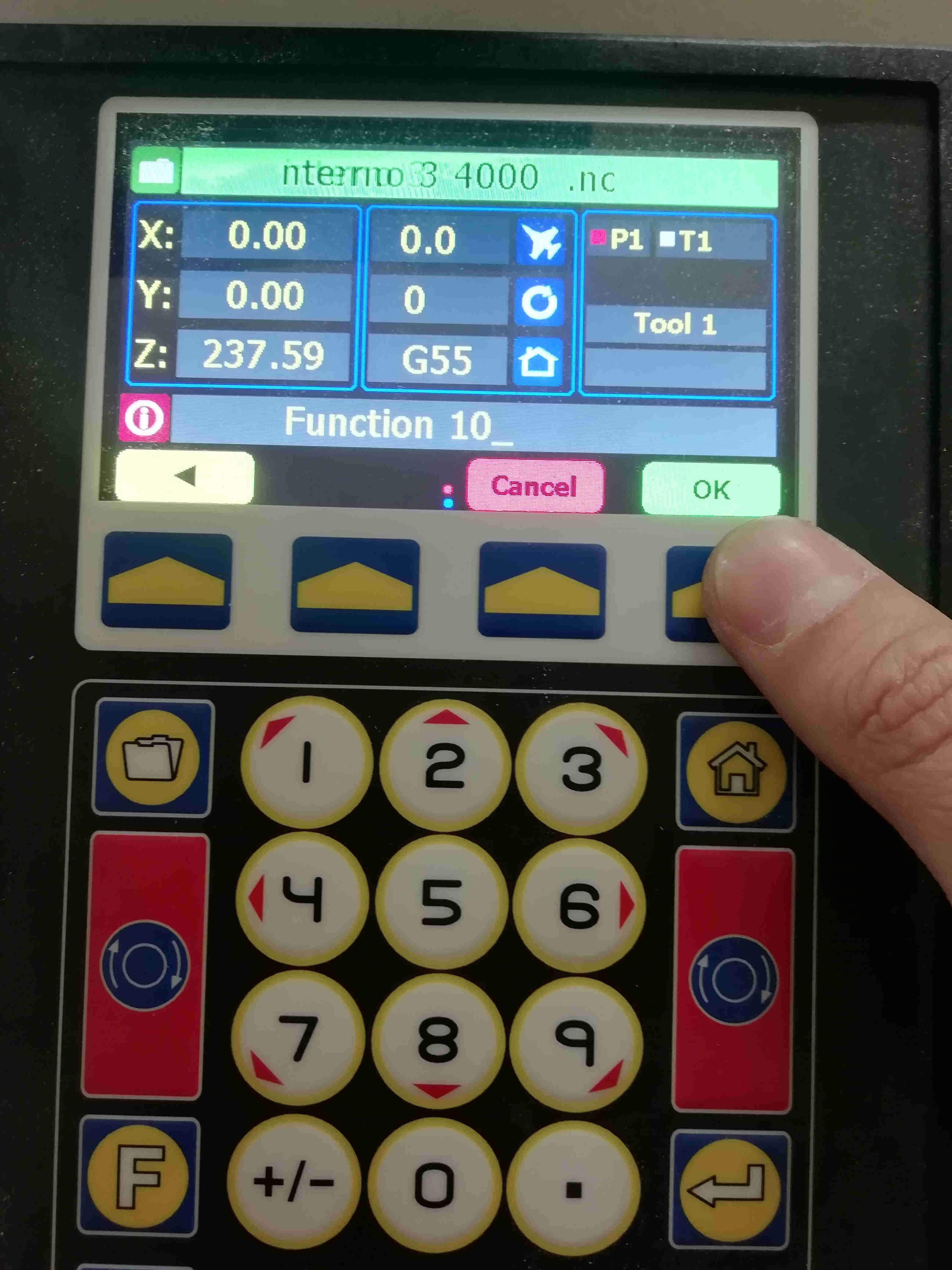 funtion 10: make a XY origin and stores it on G55
then i had to set the tool height
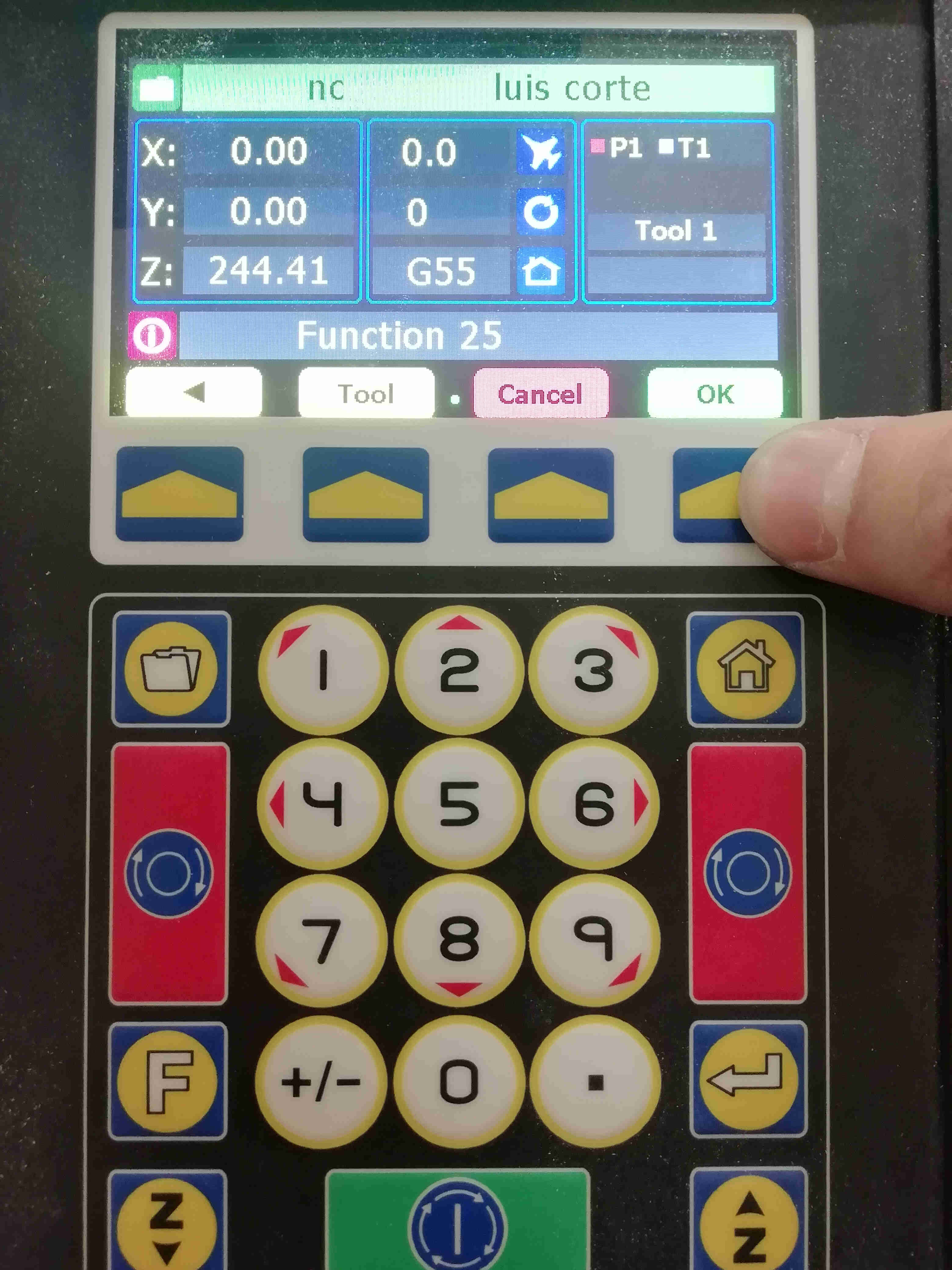 function F25 automaticly set the tool height on the spindle and stores it on T1 (tool #1)
then i have to tell the router the thickness of the material i place on the bed
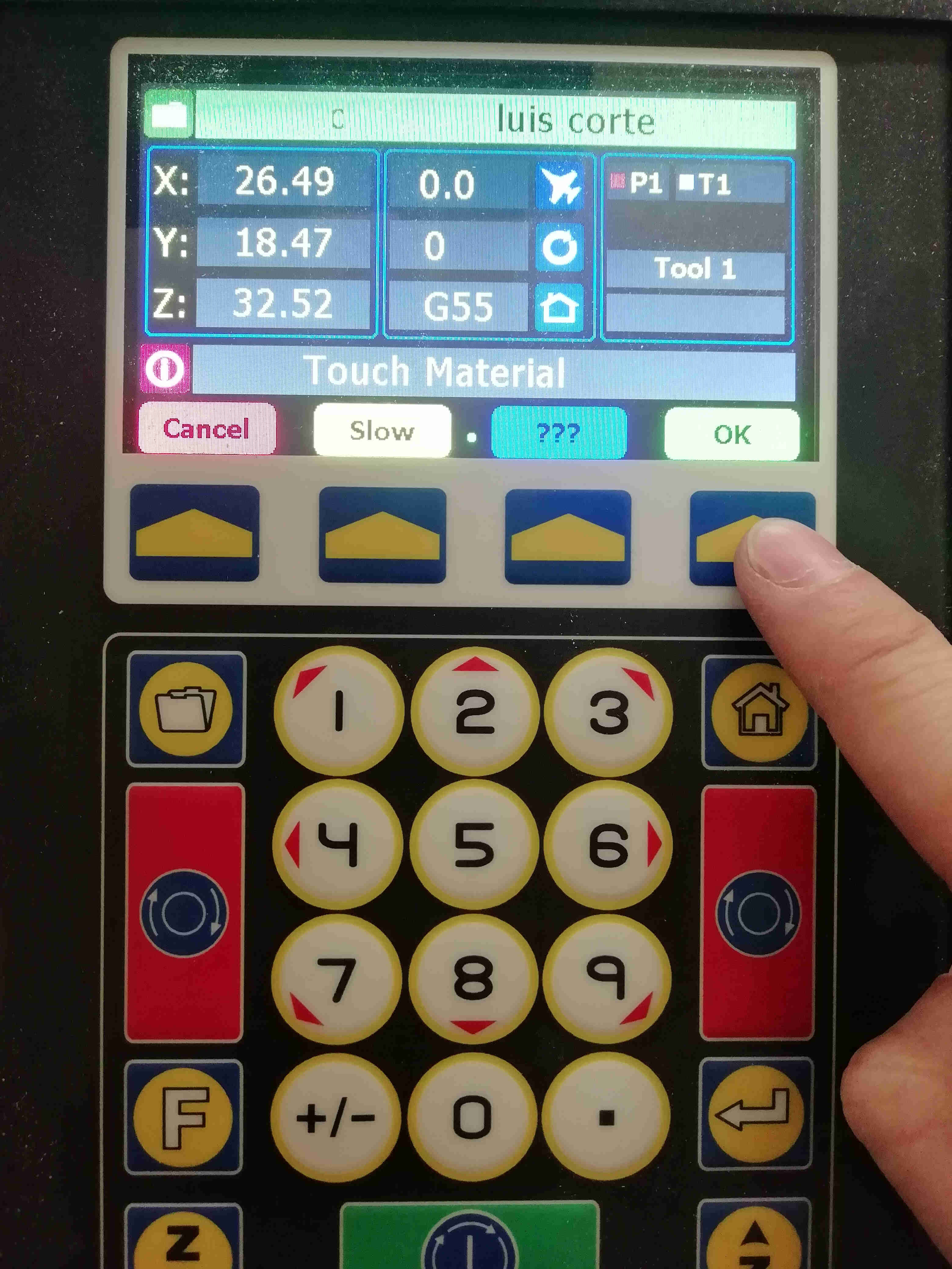 funtion 20 sets the material thickness
now i was ready to start cutting but i had an issue with the feed rate and rpms on the 1/8" endmill i used and ended breaking it so i have to replace it in order to finish my works
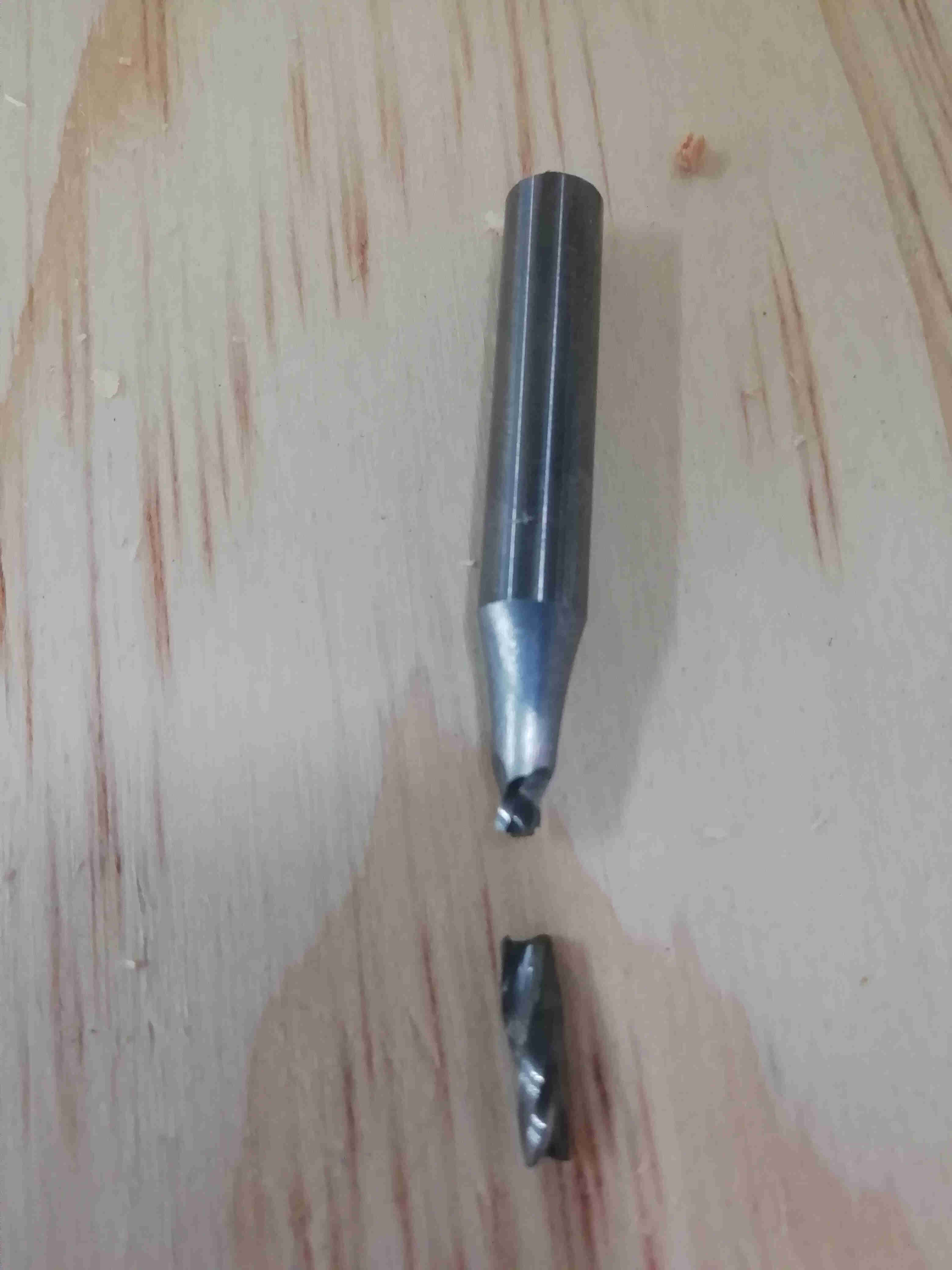 broken endmill
i have a spare but i did not have it with me at the time i was cutting
ASSEMBLY
i couldn't finish my cuts in time so i did not began the assembly
References
youtube video on furniture of plywood
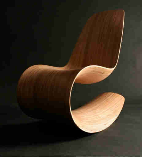 model i looked on line where i took the inspiration
Update 19/06/21
Unfortunately this is where we were sent home due to COVID pandemic. and i had to made a big pause on this assignment i tried my best to go forward with my documentation on this assignment but.
but then,the Laptop where i was documenting all of my assignments suffered an accident and had to cope with the the fact that i lost a lot of information.
show what i did on computer controlled machining after Quarantine.
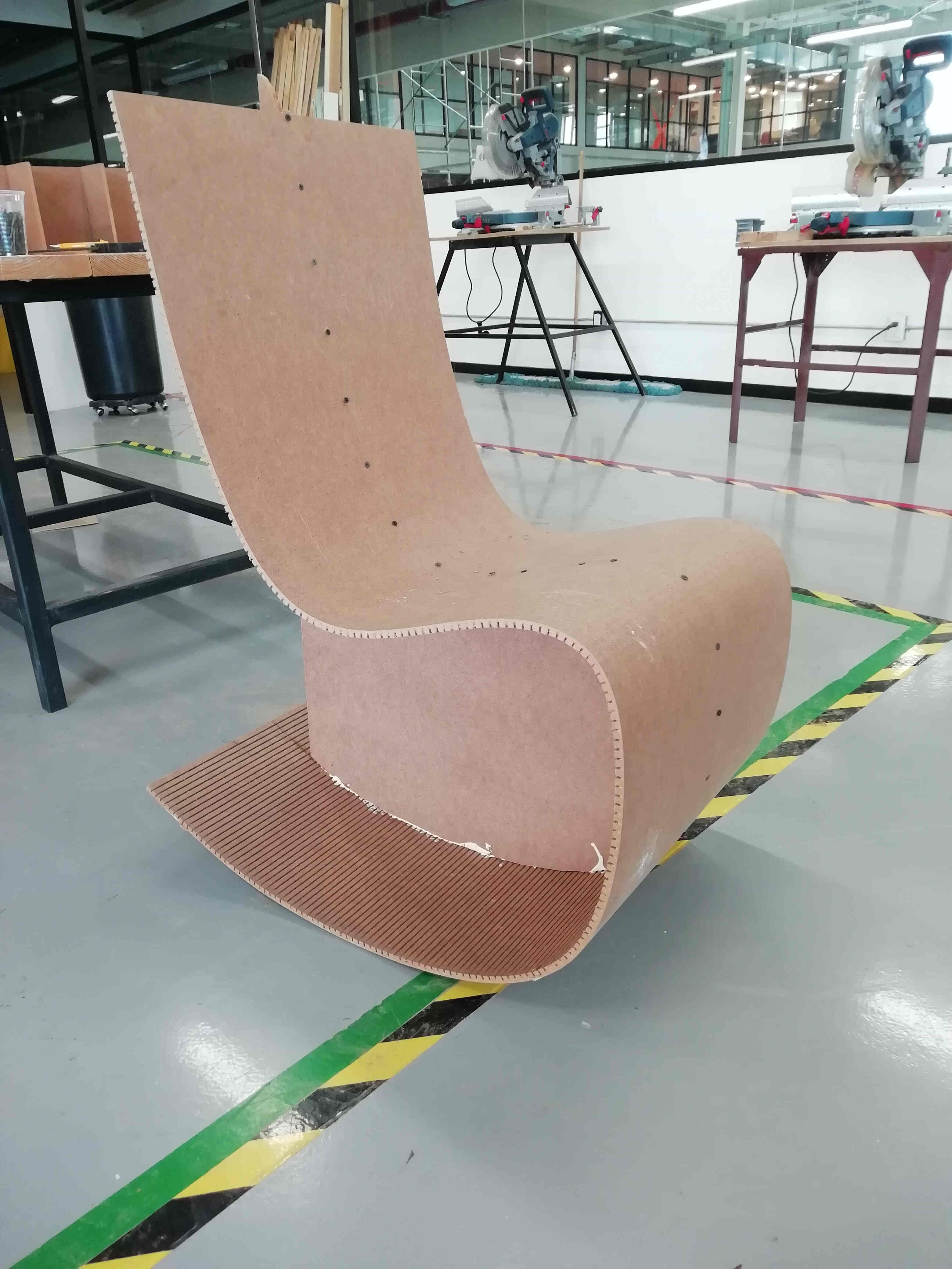 in this picture it was already glued.
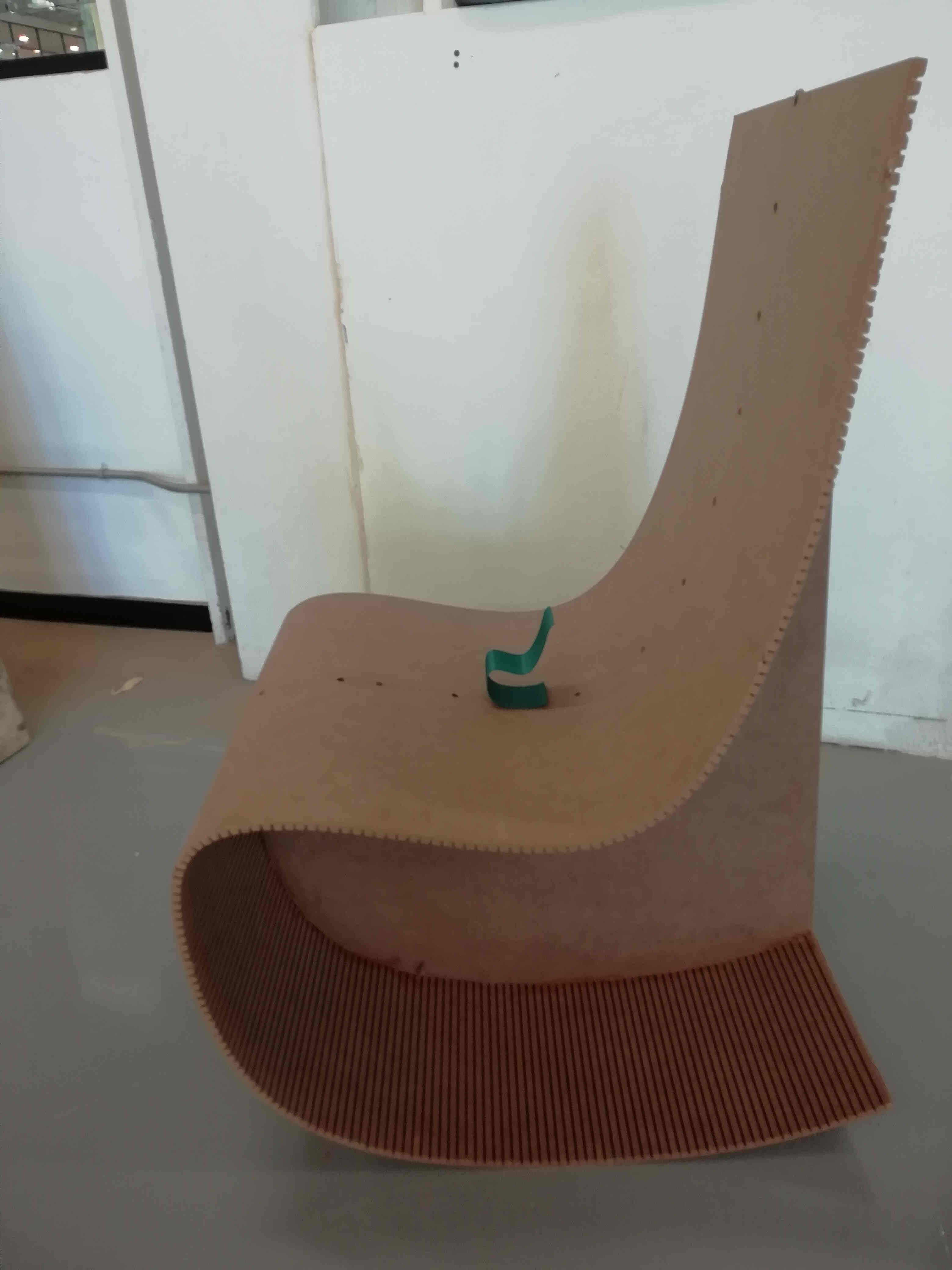 this picture was to compare the results on the curvature from the 3D print and the bended MDF.
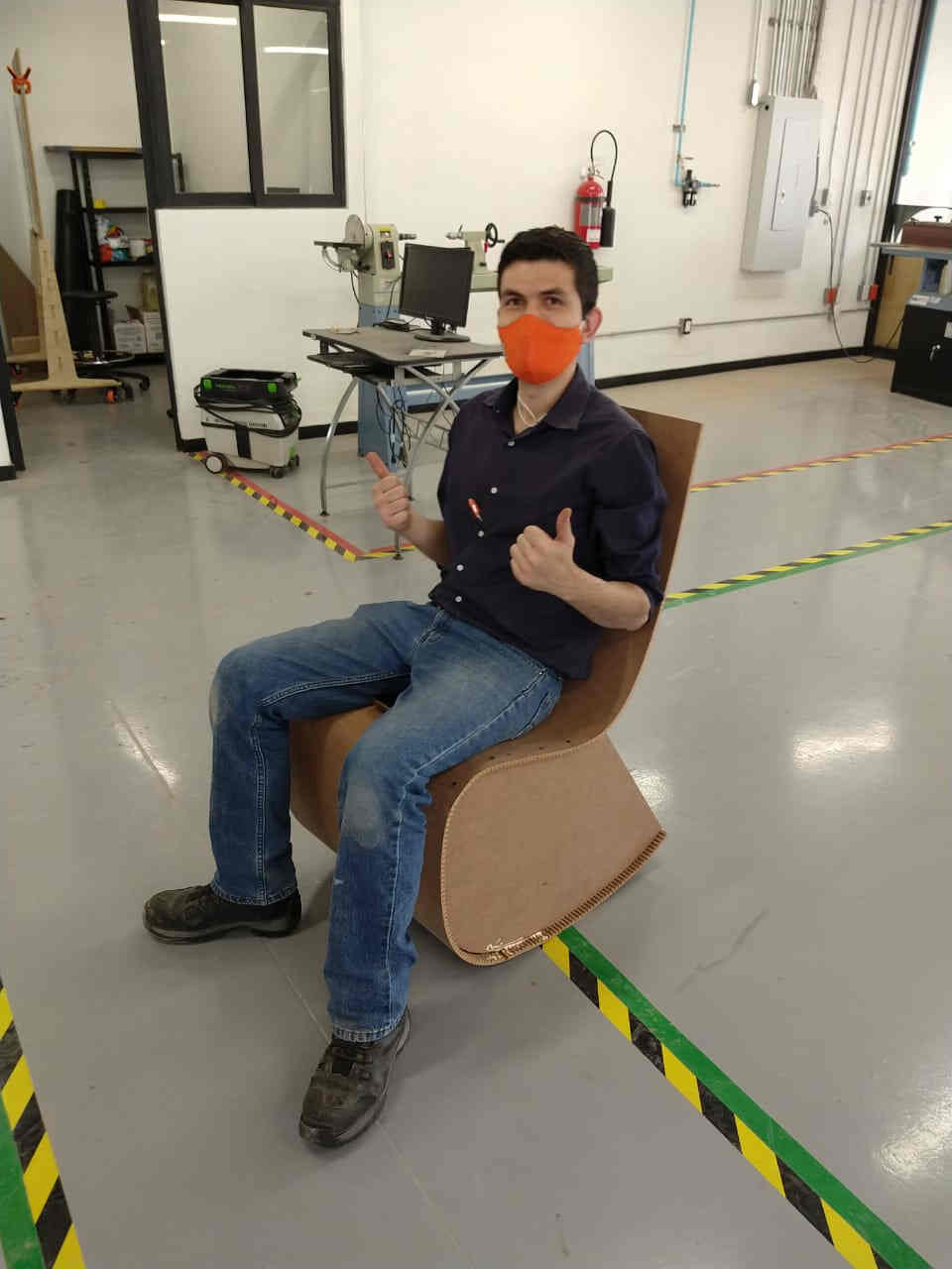 this was the moment of truth. testing the rocking chair it's is not the most comfortable but it suits me.
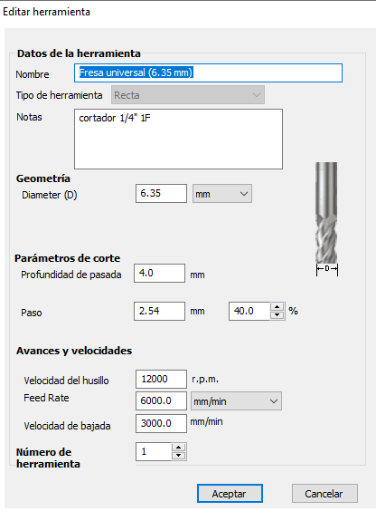 this is the speeds and feeds i used on the center piece
had to add 2 more to it's sides in order to make the rocking chair more stable
this is the speeds and feeds i used on the center piece
had to add 2 more to it's sides in order to make the rocking chair more stable
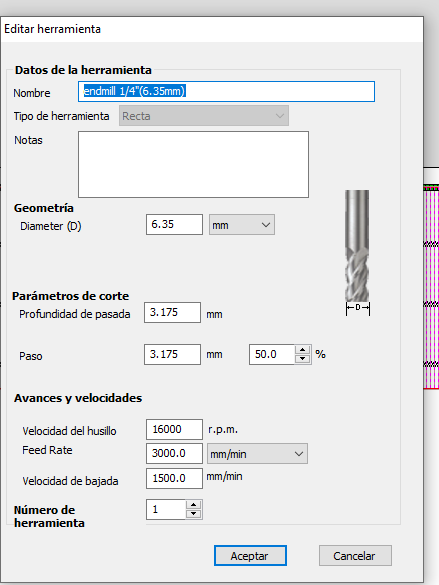 this are the speeds and feeds i used for the bending pattern.
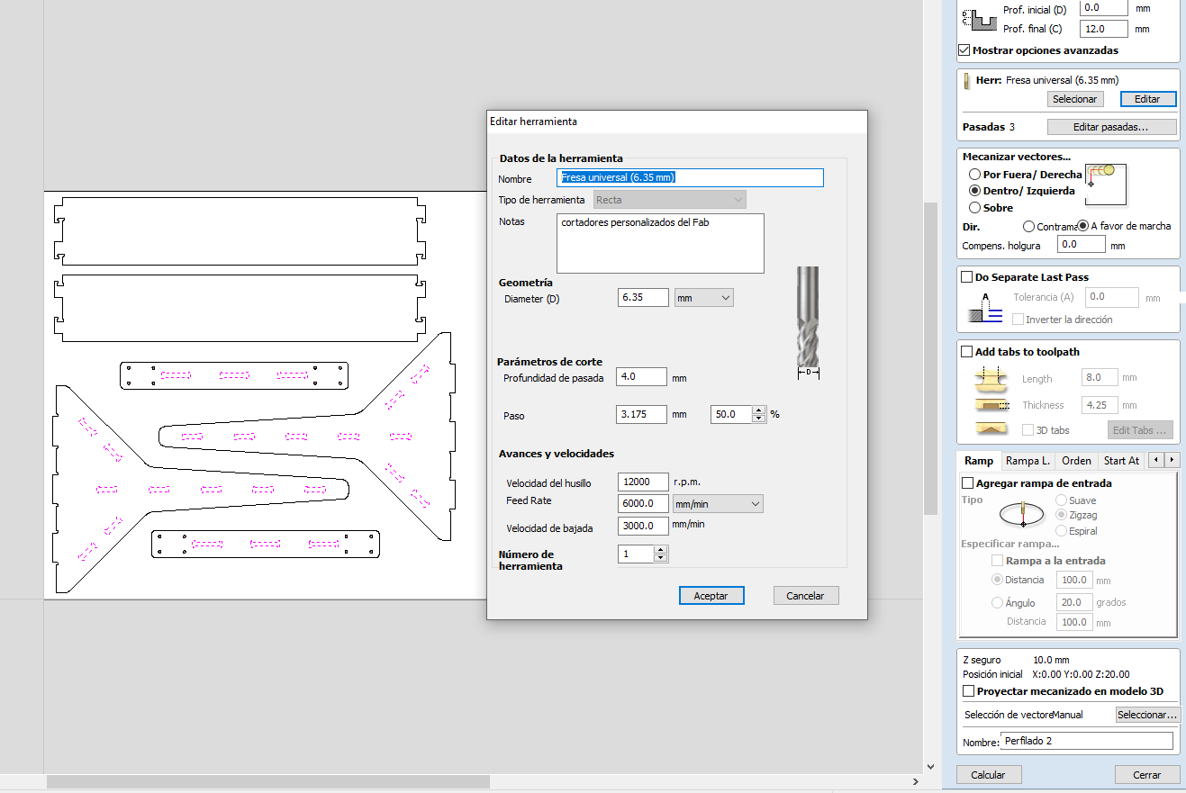
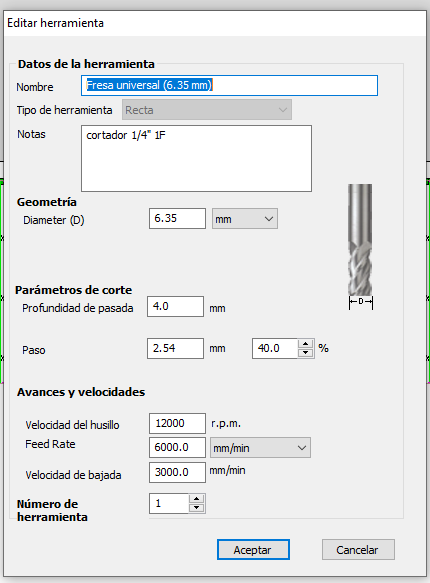 and this the speeds and feeds i used on the contour of the piece
i used diferent endmills from the library of vcarve but with the same parameters since i worked in diferent PC's at the time
and this the speeds and feeds i used on the contour of the piece
i used diferent endmills from the library of vcarve but with the same parameters since i worked in diferent PC's at the time
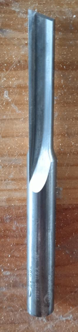
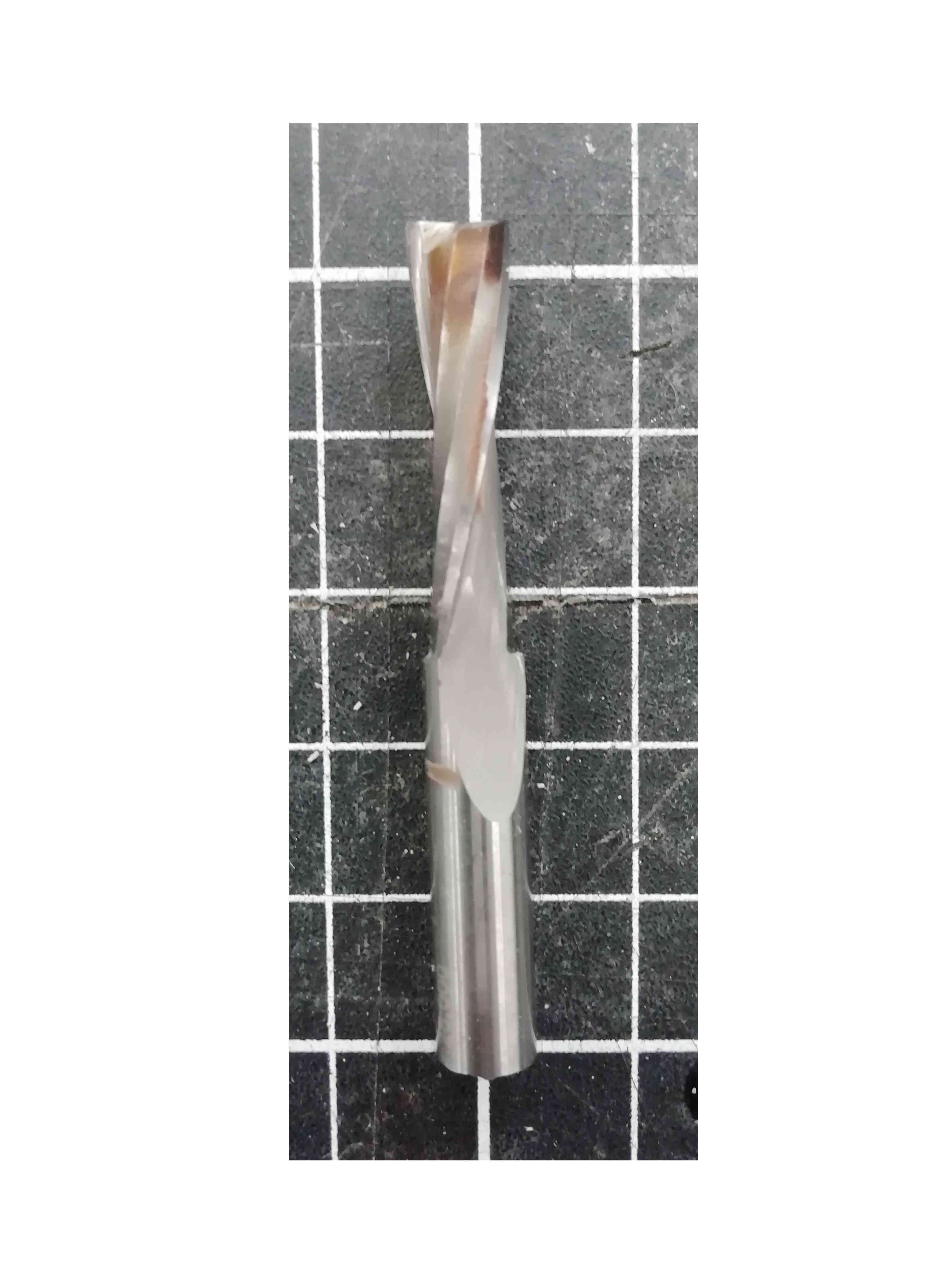 this is the actual endmill used for the whole thing
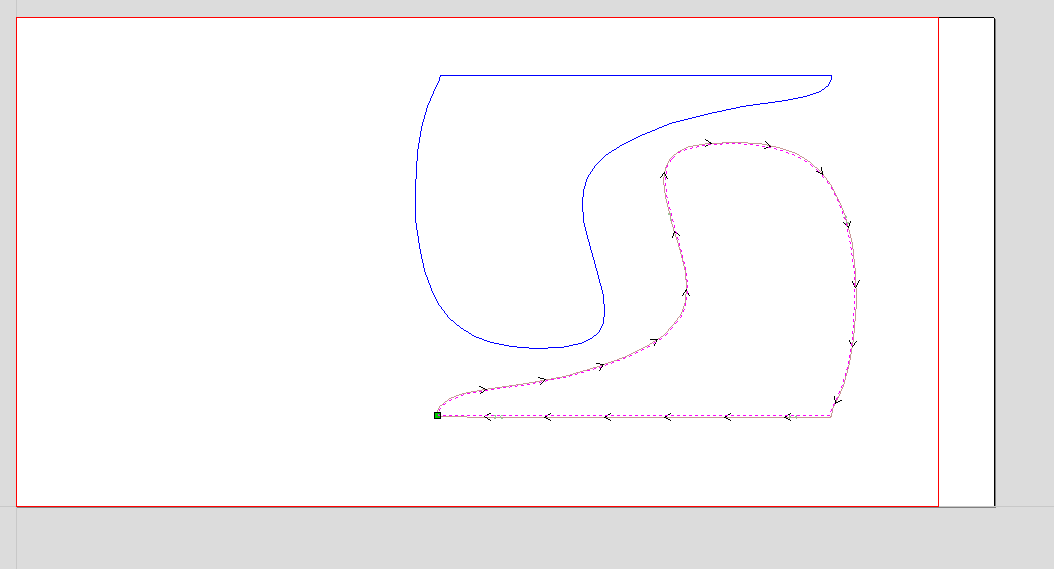
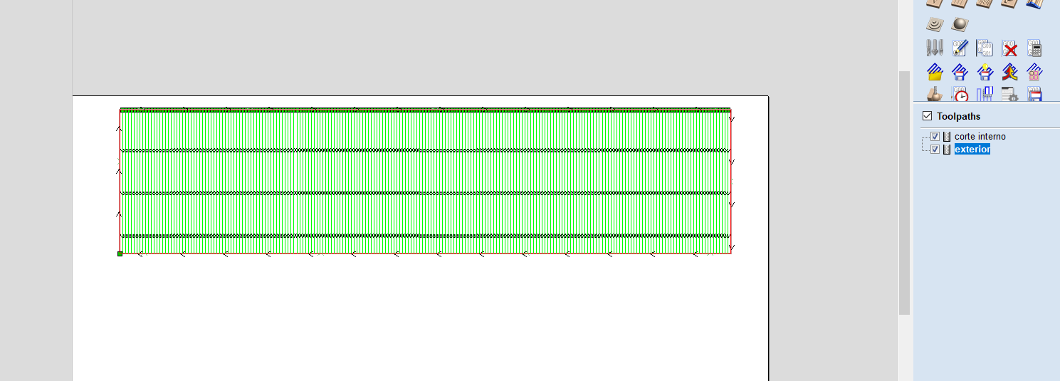 just a screenshot from Vcarve pro (diferent color are diferent operations
 the extra reinforsments used to make it more stable.
conclusions
I Really love this kind of method for bending rigid materials. I'm curretly working on some others designs. Hope to be able to finish them soon and this time make some really cool "Hero shots" of the process
From here you can get the fabrication files (Vcarve and *NC Files for the CNC router in our lab)
Also from here you can check the final assembly of the final project i worked on
Also from here you can check my youtube chanel were i will host my un compressed videos and will make more tutorials on digital fabrication.
Update 13/07/21
Individual Assignment
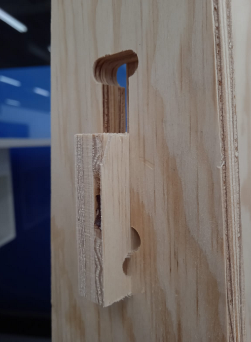
as nuria said i forgot to use cnc joints on this model in particular.
Luckly as i work in the fablab i'm constantly testing the endmills and the speeds and feeds.
So here i'll try to summarize really quick another model recently made on the fablabqro.
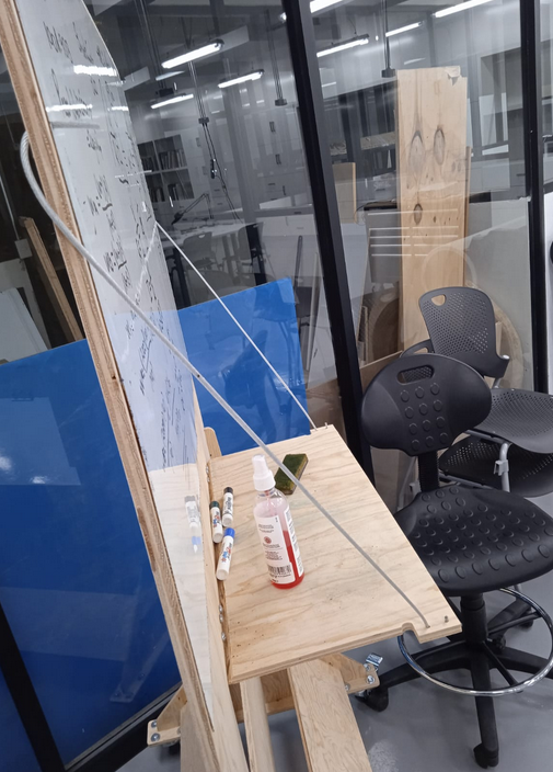
So the idea of this portable whiteboard is to carry it with you arround the workshop.
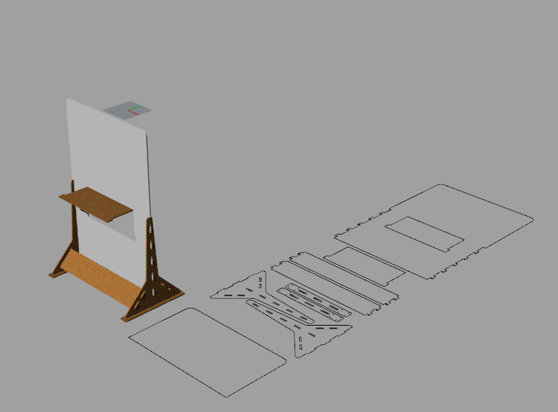
this is just a screenshot of the rhino file
as we are constantly using the laptop or the eraser it has a litle foldable table.
Then after creating this to just made a merge toolpath since both of them uses the same endmill
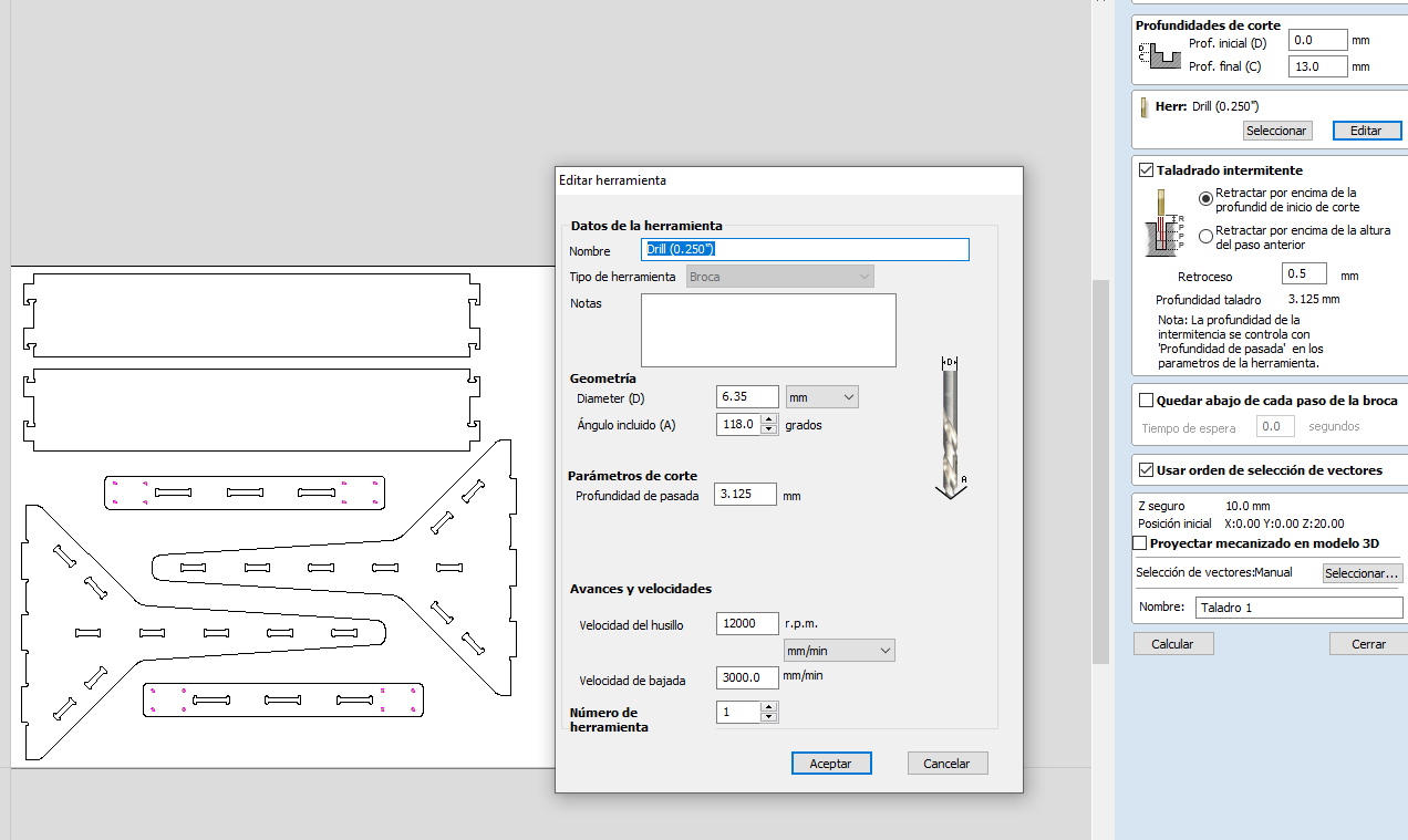
for the holes i used a standard 1/4" diameter high speed steel(HSS) drill bit
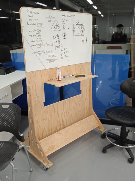
Here's a picture of the final product already assembled.
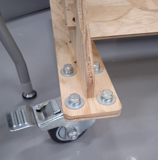
here a little image about the caster.
LINKS AND REFERENCES
HERE you can download all of the fabrication files (rhino 5,Vcarve pro 9.012 and g-code files for a millimetric AXYZ Z7 CNC router)