Computer Aided Design
Assignment 2: model (rester,vector,simulate,...) a posible final project, compress your images and videos and post it on your class page
For my second week con fabacademy i tried to use freecad as my CAD tool however i found it a Little to complex to use as a start point because i want to use only one cad tool to all my Project and i needed a cad tool were can make it simple and quick, because of my mechanical designer and experience using Solidworks i finally came up with this tutorial in wich i will show you how to créate multiple configurations to make one piece and have multiple choices within one file.
Update 18/06/21
Since i'm an electro-mechanical engineer i'm used to the solidworks enviroment for a while now. i also use a little bit of Autodesk's inventor, Fusion 360, Rhinoceros 3D, Grashopper, Autodesk's AutoCAD, Autodesk's EAGLE. but each of them has pros and cons... depending on wich machine i'll be working or the purpuse of the final model. it's the software i'll probably will be working on.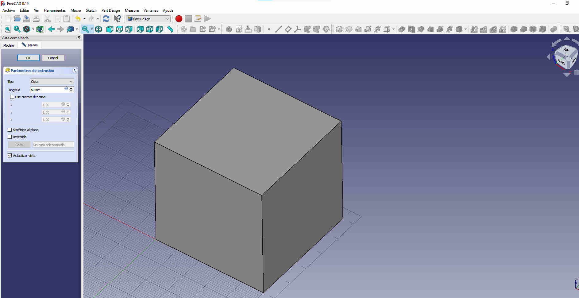
this is a screenshot from were i goofed around a little with freeCAD
as i said i'm a little more fluent on solidworks than any other, so it's usually my first choice for every project. i tried FreeCAD in the early begginings on the Fabacademy2020. Although it looks similar to solidworks in several aspects. i determined that learning another modeling software just for this would be a little to much and decided to go with a tool i already know how to use. and focus my attention in all the other softwares i did not how to use.Tutorial on Solidworks using configurations
First thing first you will need to create a new part file
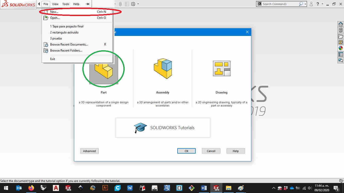
Open up your Solidworks and then go to new in the file tab and select a part fileThen it will open the workbench for partsHere you can modify any piece you like from sketches up to simulations.Let's make a sktech.
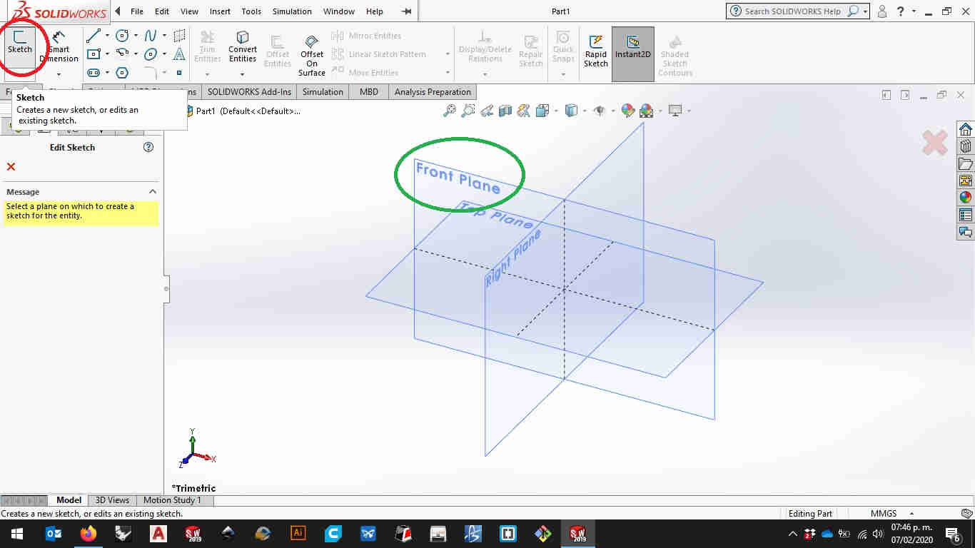
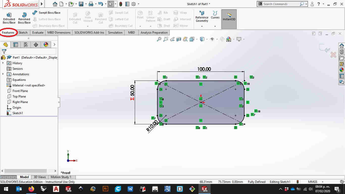
Go to the sketch tab on the upper left side of the window and select a plane you’ll be working with.(i usually work on the top view but for 3D printing, laser cutting and other machines is better towork in the front view) Let’s make a initial sketch
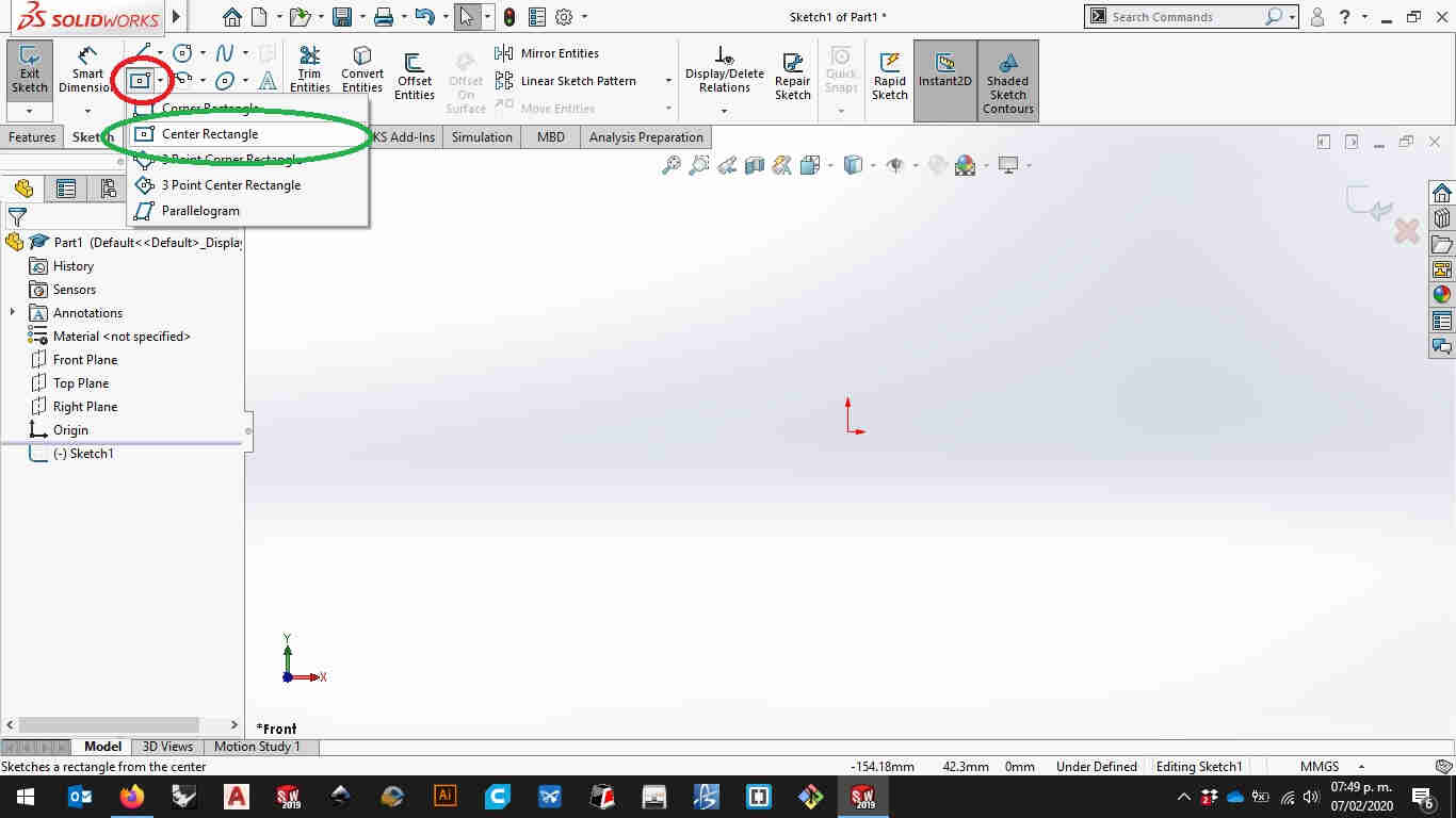
in the sketch tab you’ll find the tools you need to draw geometric figures.
As a good practice i usually grab the ofigin on the center to start drawing this helps you to get your drawing totally defined.
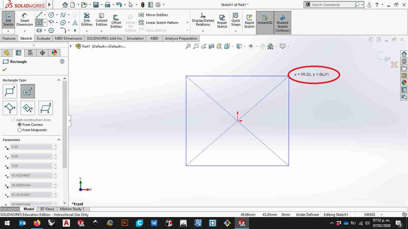
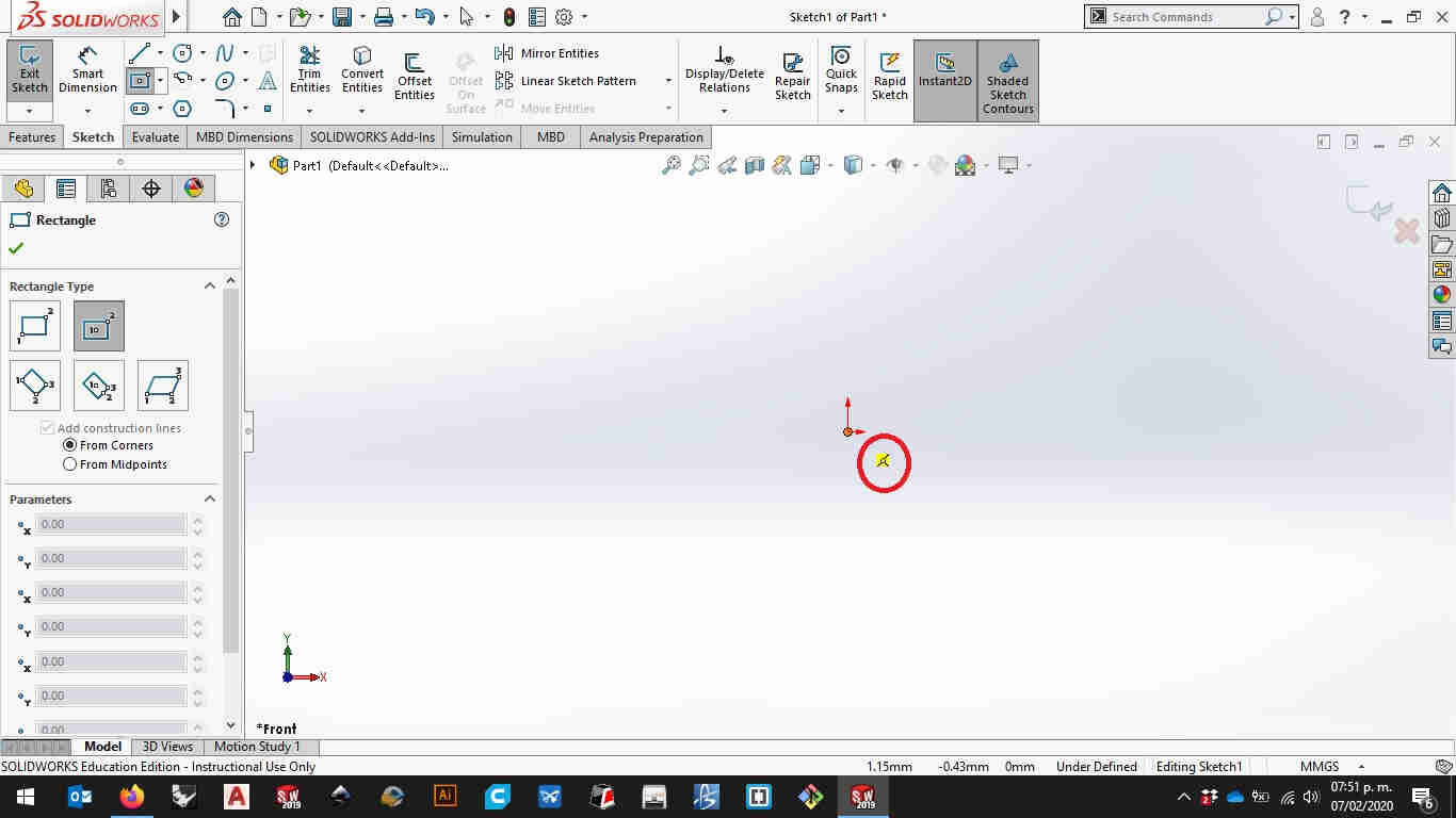
First click on the origin and second click anywhere you like.
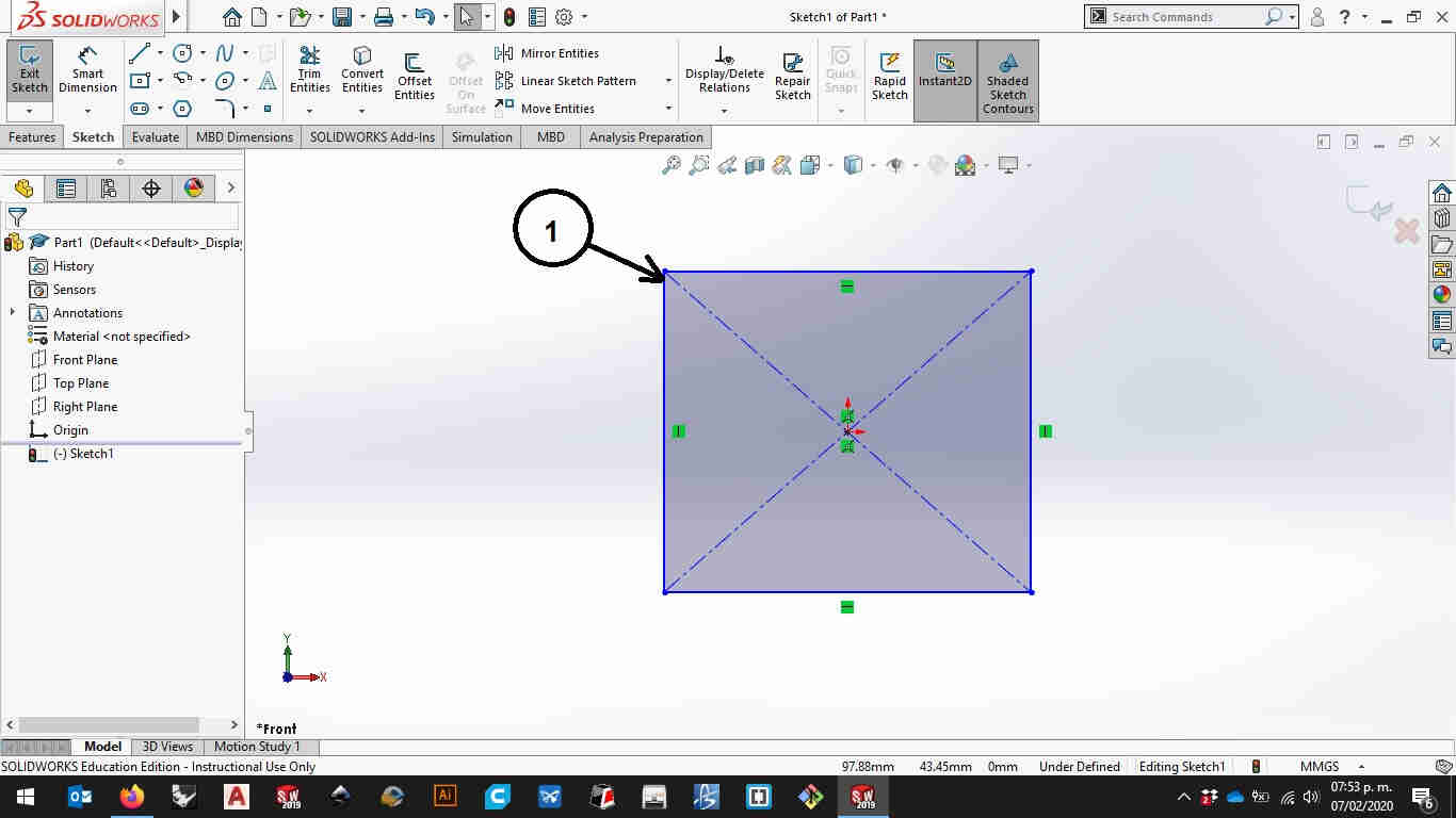
Here you will notice that your sketch look a Little odd. Don’t worry this is normal. The solid lines will make your figure and the dashed lines are just for reference this will not be of use when you créate solids.And your sketch looks blue?! Why is that? It’s because your sketch is underdefined…what’s that? Well solid Works uses geometrical constrains to define the geometry you’re creating. Like (parallel,perpendicular,equality,concentric,dimensional constraints, and a larger etc) Now let’s put some numbers on the figure.
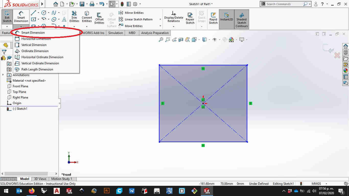
Using the Smart dimensión tool on the sketch tab you can put numeric values to lengths and angles. Jus click on the line you like to set the dimensión.
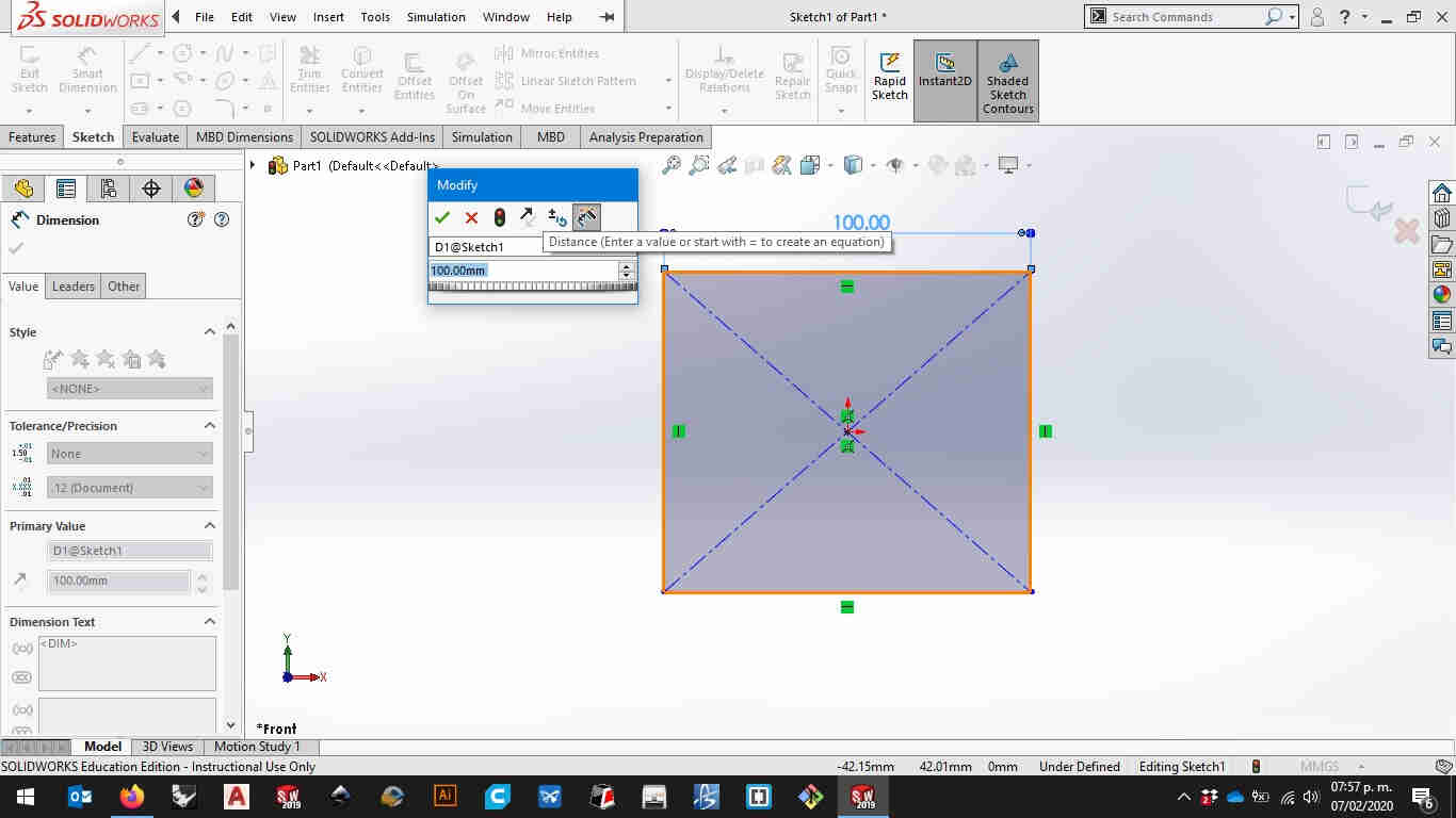
On the modify window you can set a name vor your variable and a value.
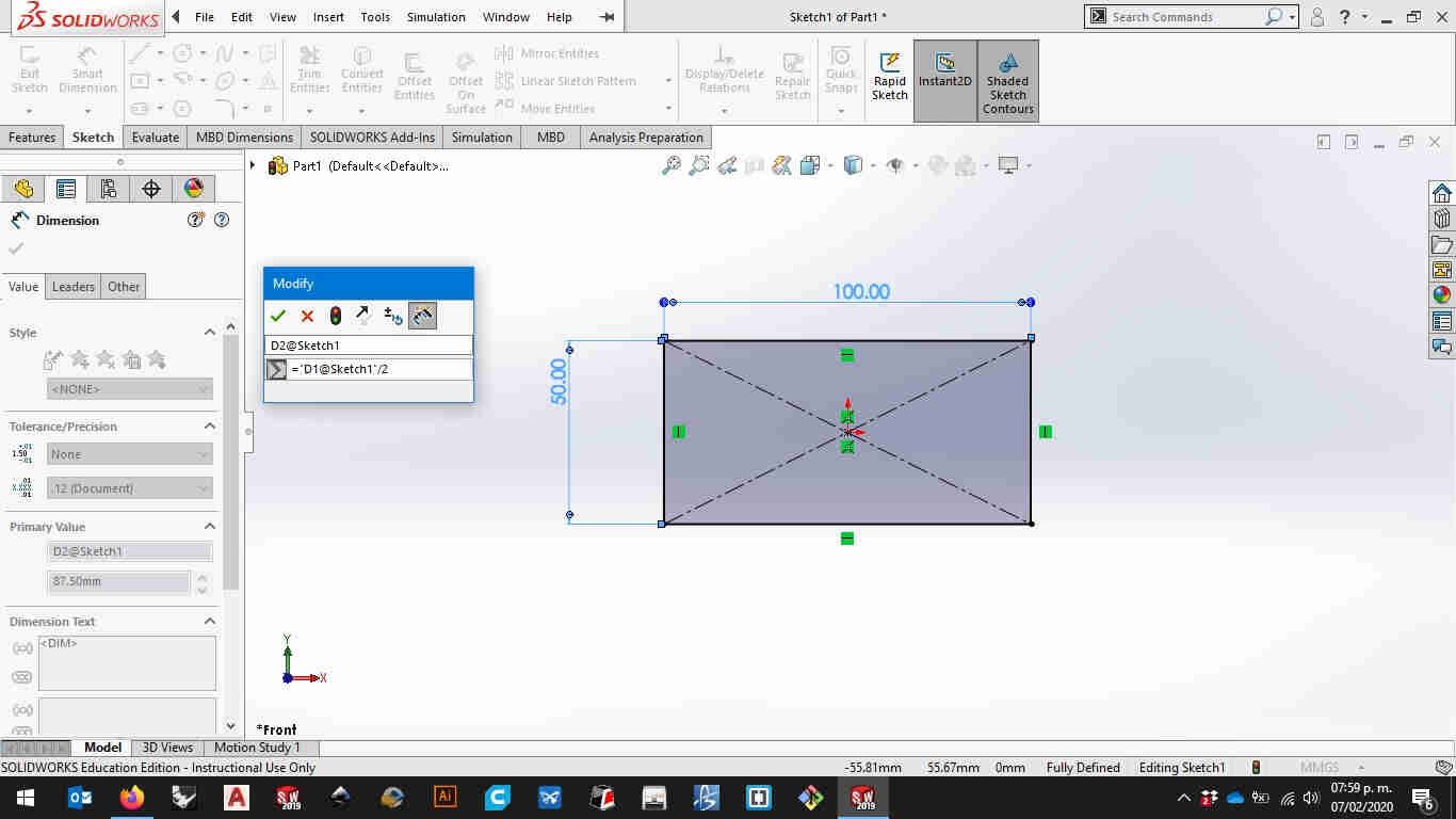
It could be a numeric value (6), an arithmetic operation, (3+3) or a mathemathical expression setting “=” before the sentence like in an Excel spread sheet (=pi*(variablename@sketchyoureon))
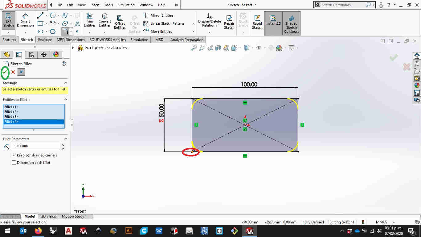
Lets make some fillets using the fillet tool and defining the radius of it in the left side panel on the window and press enter or click on the ok button.
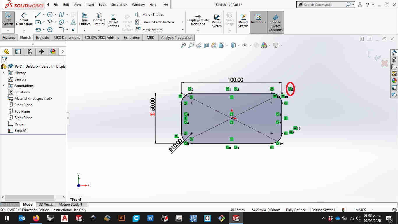
As your figure get’s more complex you will need more constraints to define it solidworks will create some for you. But you have to make sure you don’t over define by putting to many constraints on the sketch.Now we’re ready to set a thickness and make your 3D model
Go to the fetures tabo n the upper left ribbon menú and select extrude boss/base
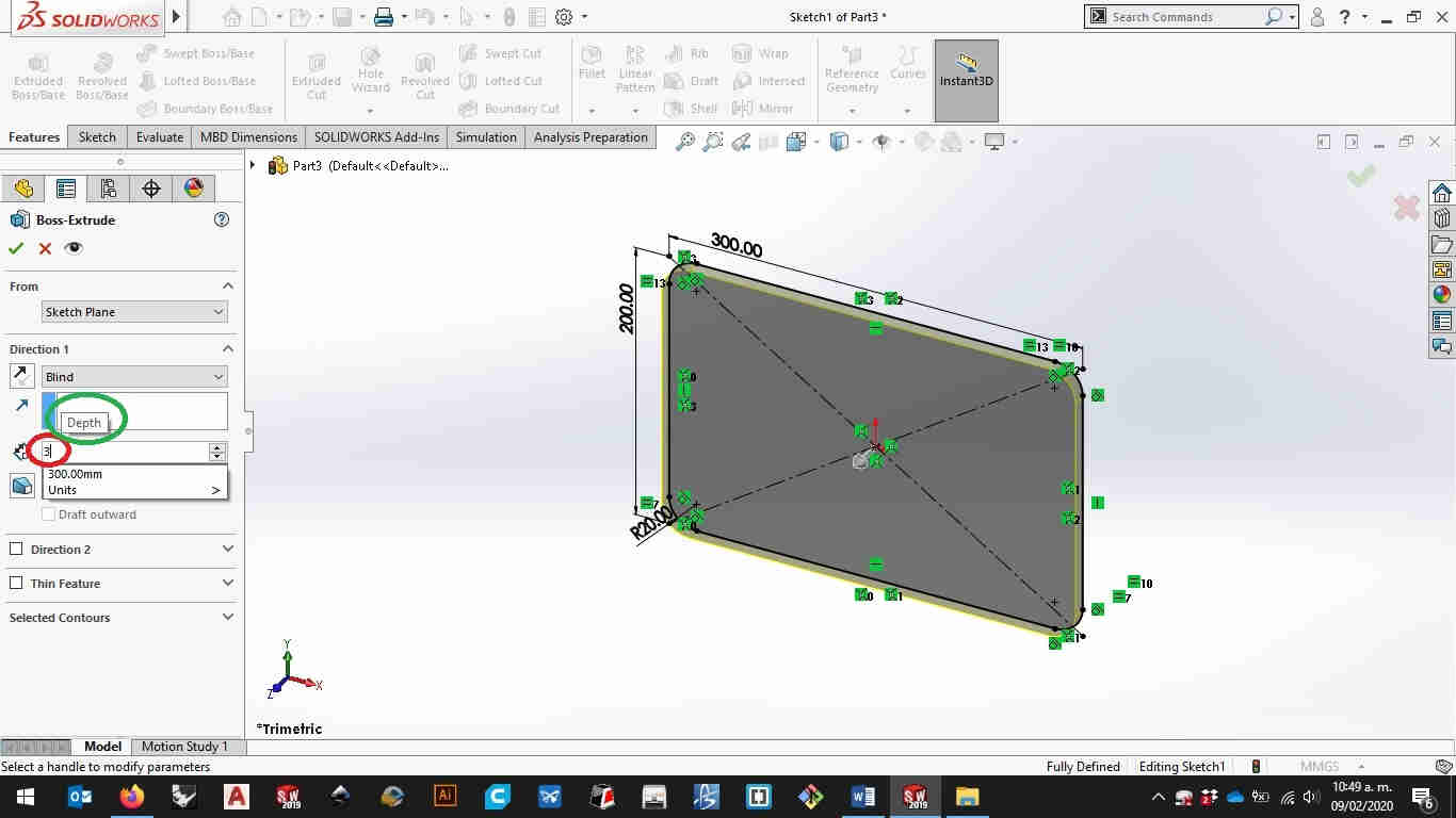
Here you can set a value on blind or you can set another mathemathical expresión then hit enter or click on the ok button
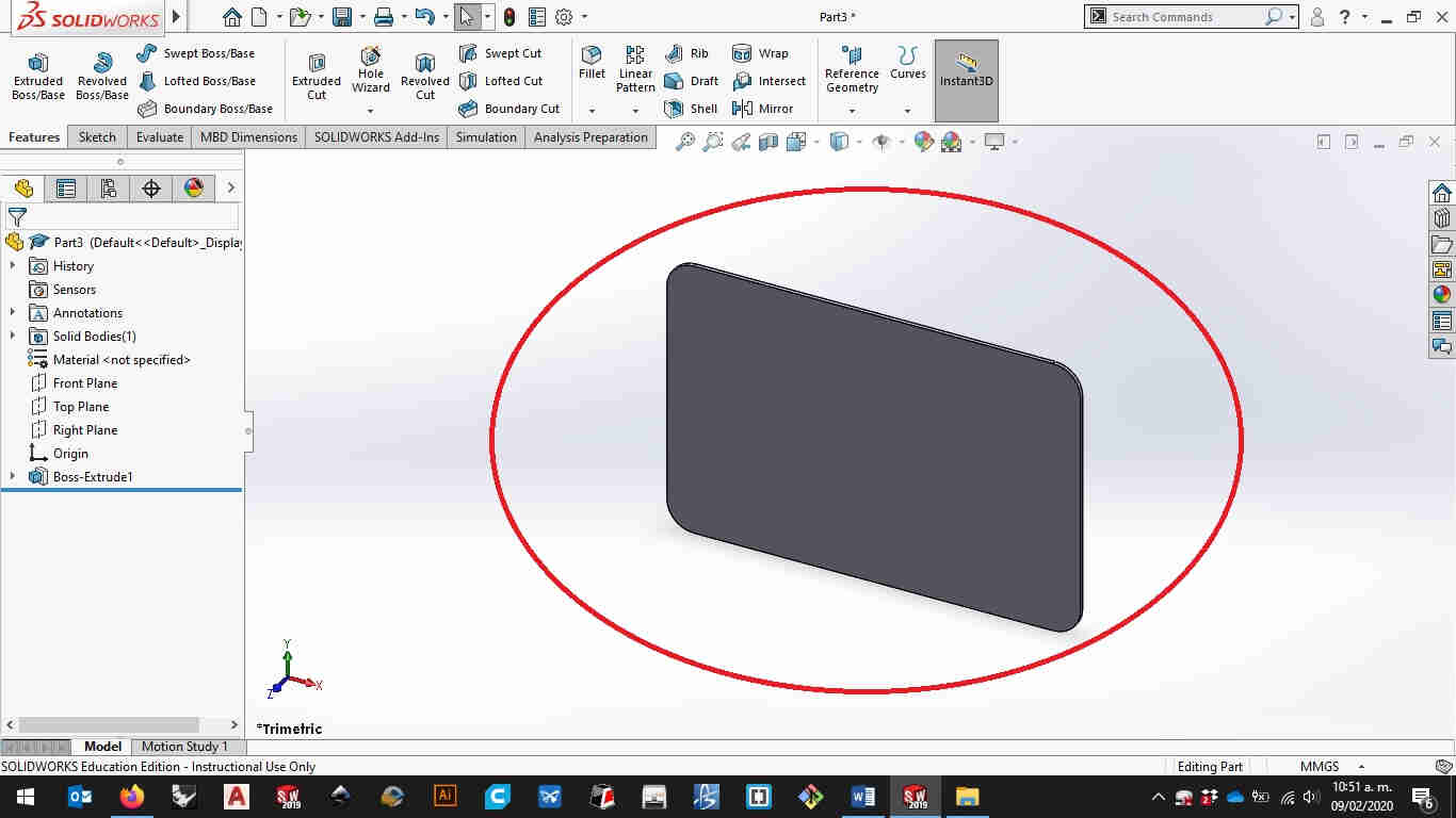
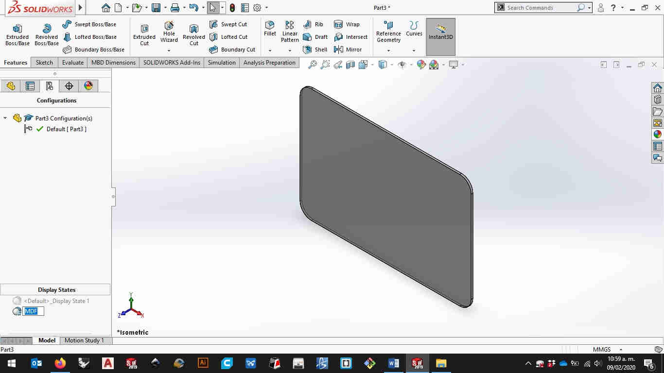
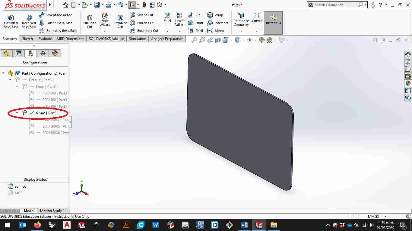
Now you have your first solid by default solidworks gives you a gray visualisation.
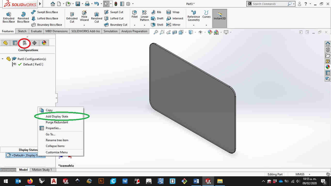
You can change it by clicking on the configuration manager on the left side panel and right click on the default display setting to add a new display state.
You can rename it by pressing the F2 button on the keyboard i ussualy name it like the material i’m using.
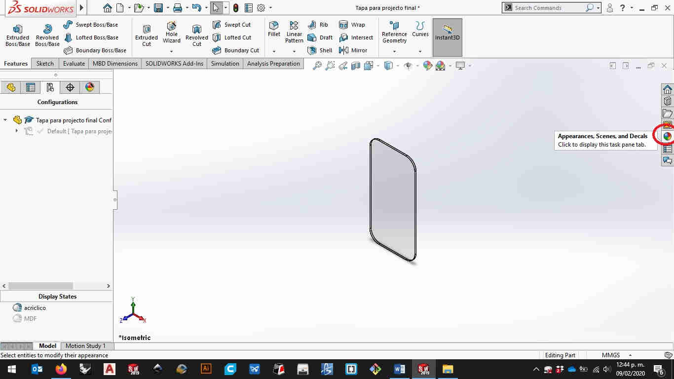
On the right side of the window you’ll find the apareances tab clic kit and it will open a menú were you can drag a texture over your solid.
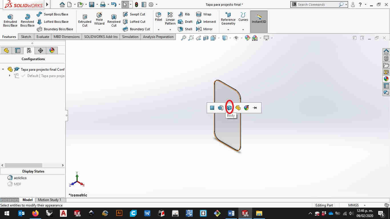
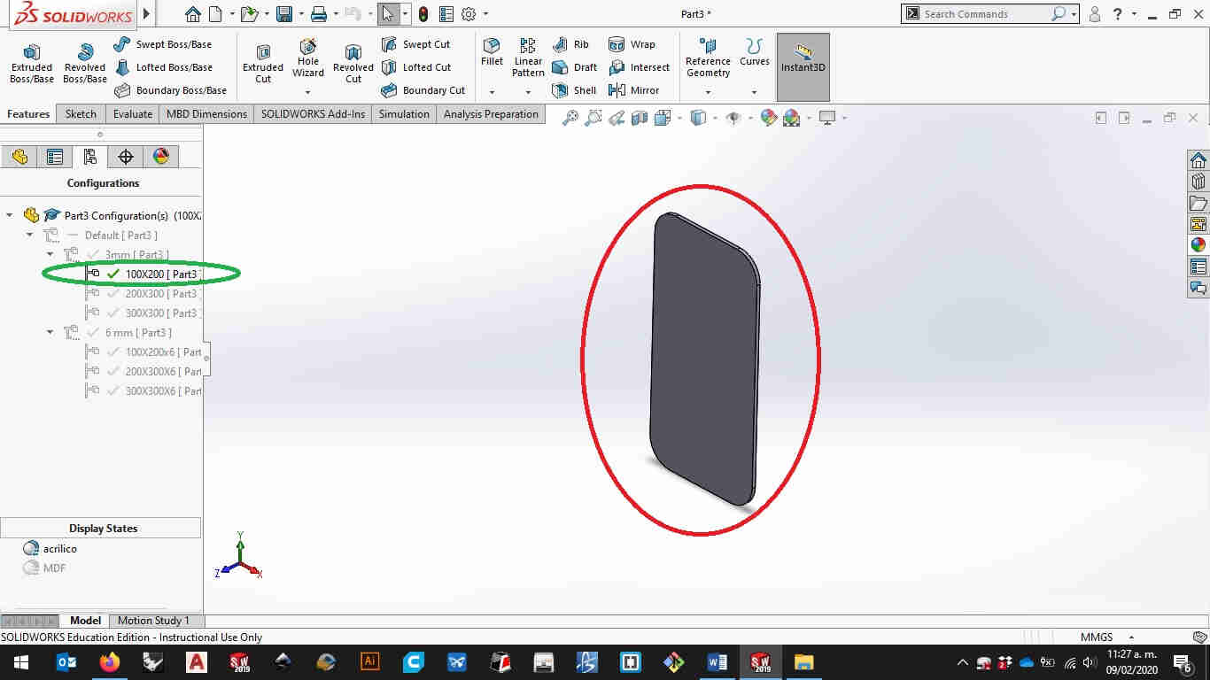
Then select the body option to place your texture on the solid you’re working on. Now let’s make some configurations to the dimensions you just créate to make diferent versions of the piece youre working on.
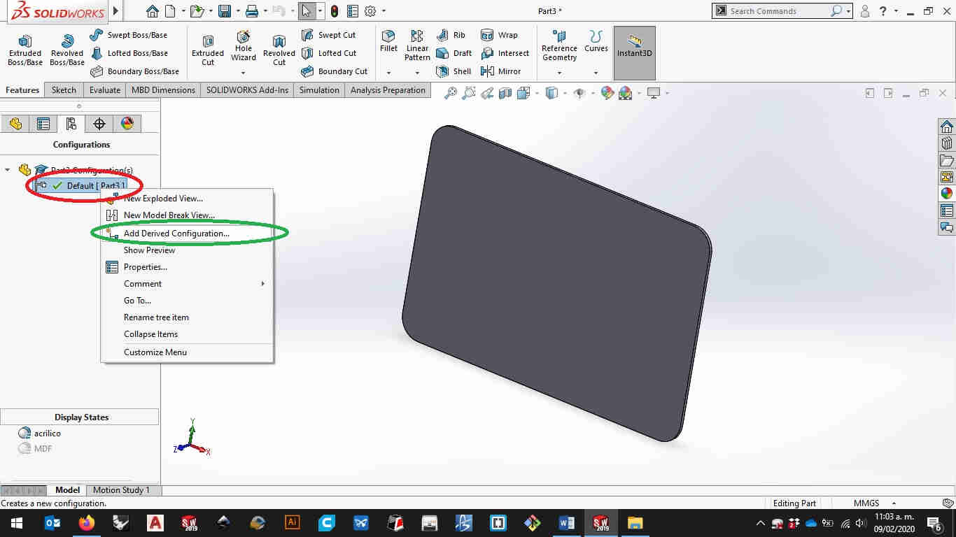
In the configurations manager right click on the default setting to add a derived configuration.
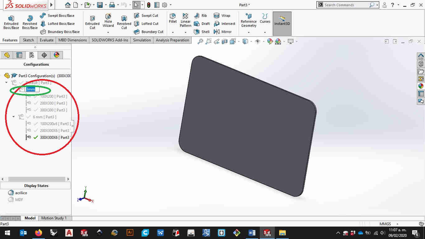
Will recomend you to keep it clear and tiddy because it could get a little bit confusing wwhen working with bigger pieces. I créate a master configuration for each thicknes i will be working and then individual confirations for each thickness.
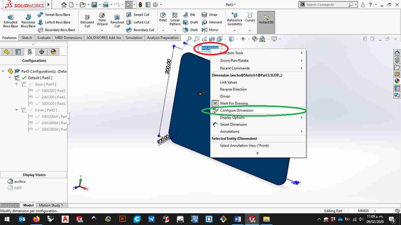
Then let’s click on the solid and right click on the dimensión to enter “configure dimensions” option.
Here you can caracterize your the dimensions on the sketch you’ve just made. Once you’re finished press enter or hit the ok button.
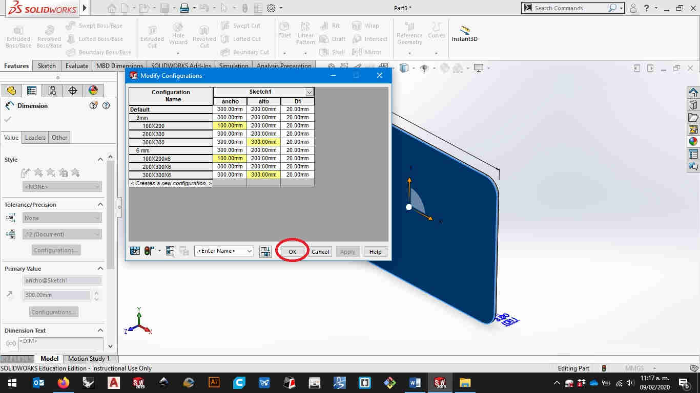
Here comes the trickier part. Let’s make the extrusión part of the configuration. For this you hav to go to the thickness you want to modify.
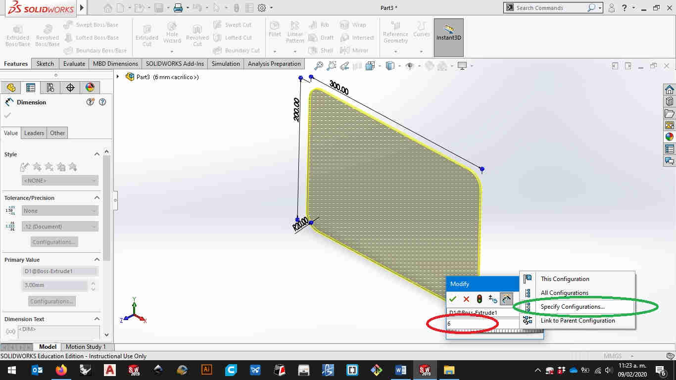
Then click on the solid part and double click on the dimensión. Modify it but before you hit enter make sure you click on the “especify configurations” option.
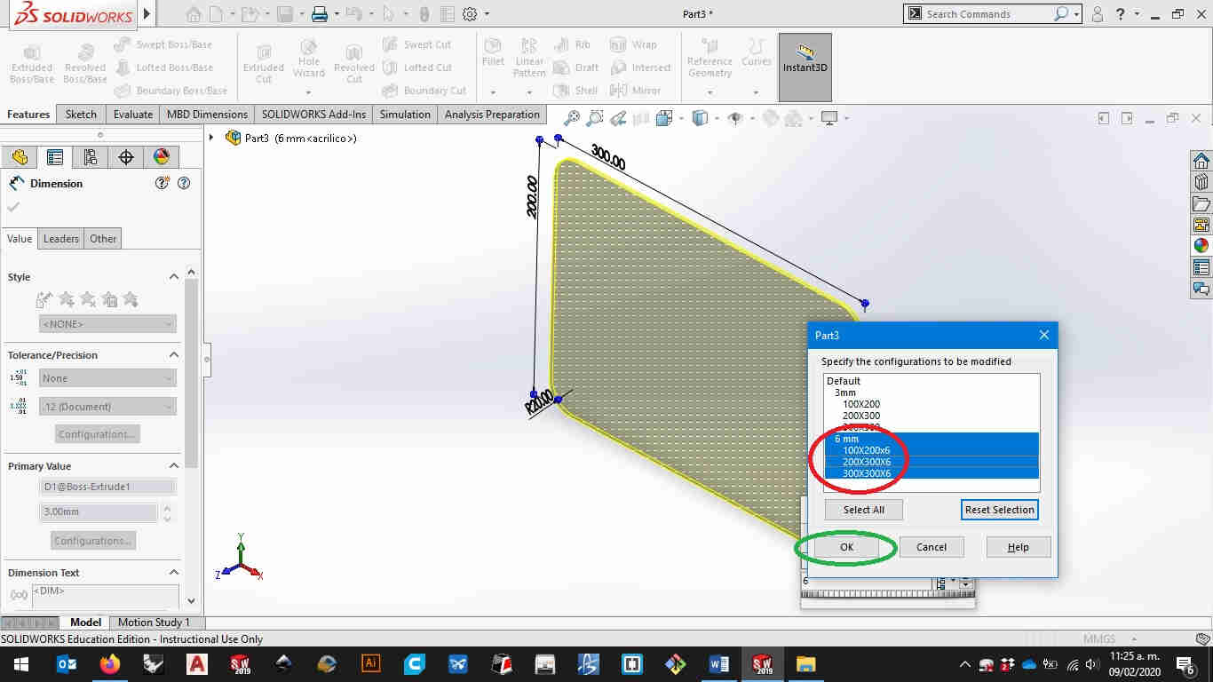
From here you can select the configurations you want to have this thicknes and when youre done click ok to set it.
here i will let a video tutorial following all the steps so you can make it yourself.
from HERE you can download the file of this tutorial
video tutorial for computer controlled design
in this short video i demostrate how you can use the same file to store diferent versions of the same model. in my final project i used 2 "types" of hinges one left sided and the other right sided.HERE you can follow what i did with those files for my final project
from HERE you can download the hinges from this tutorial
Update 25/02/21
video tutorial for computer controlled design
sketch a potential final project
this is acctually the first version on my final project the final version and fabrication files are on HERE.
from HEREe you can download the files for this assembly.
Links and references
HERE you can download the tutorial on the configurable rectangle
HERE you can download the configurable hinge
HERE you can download the files of the solidworks assembly on the final project