group assignment:
measure the power consumption of an output device
individual assignment:
add an output device to a microcontroller board you've designed,
and program it to do something
For this work, the Eagle software was used to design the board and the Josanino board was used as a base (see additional information at the end), but several components were added that will be useful for the Final Project. The components that were added were:
HiLetgo A4988 Stepper Motor Driver Module with Heat Sink
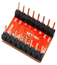
- Pololu
- Headers for connecting phototransistor sensor boards
- Resistor 0 OHMS
- DC Jack for power
Pololu are stepper motor drivers that are specifically designed to drive stepper motors, which are capable of continuous rotation with precise position control.
Model: A4988
Logic supply voltage: 3V to 5.5V DC
Output voltage (max): 35VDC
Number of pins: 16
Short circuit protection.
It has a heatsink
Size: 15.2mm x 20.3mm
Weight: 1.5 g (without connectors)
Output current: 1A per coil (max 2A with fan)
Five step resolutions: full-step, half-step, 1/4, 1/8 and 1/16
Outputs : Low RDS (ON)
Automatic current drop detection
Synchronous rectification for low power dissipation
Internal UVLO
current-crossover protection
Internal thermal protection circuit
Ground Fault Circuit
short circuit protection
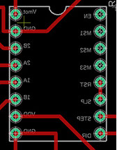
12V
- Pololu pins
GND
With the DIR and STEP pins we control the direction of rotation using the instruction:
1 (one) clockwise
0 (zero) counterclockwise
pins where the motor connects
GND
GND
12V
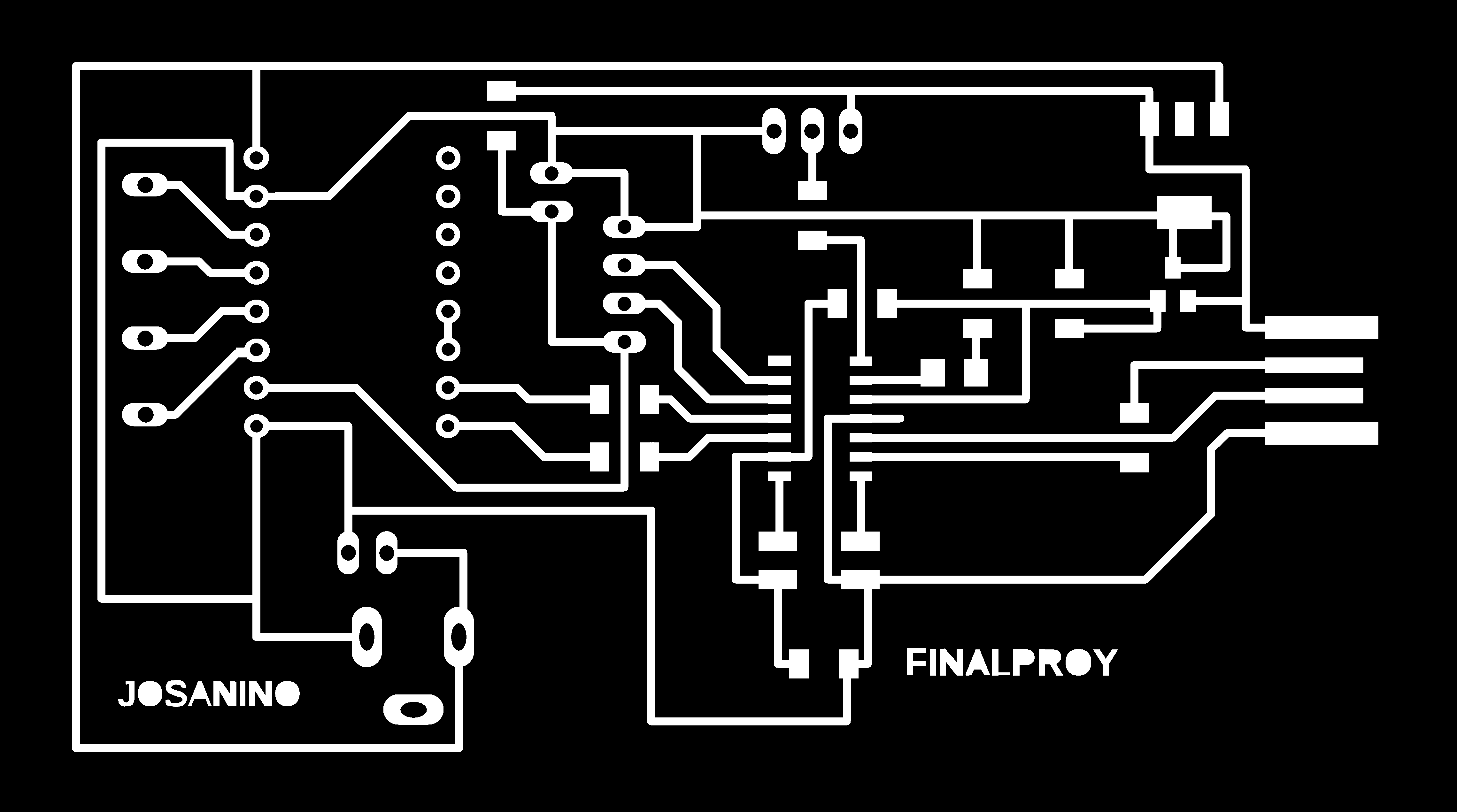
This board called Josanino Final Project will help us to control the bipolar stepper motor that will take the machine of our final project.
Bipolar stepper motors have two coils with no midpoint where a wire exits, so there are four wires and each pair corresponds to the terminals of a coil. Given the configuration of the coil, current can flow in two directions, necessitating bidirectional or bipolar control. The direction of rotation of bipolar stepper motors depends on the direction of current flow through the coils, since this induces a magnetic field in the winding that generates a north and south magnetic pole, hence the rotor moves so that one of the poles of the rotor is opposite to that of the coil

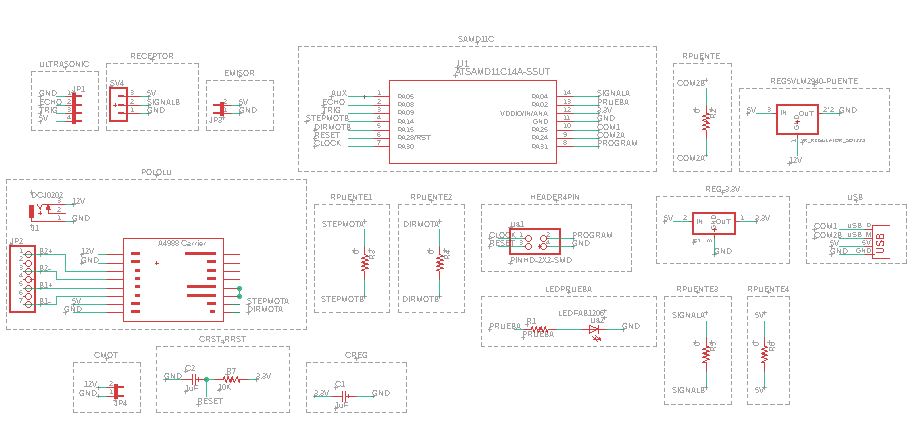
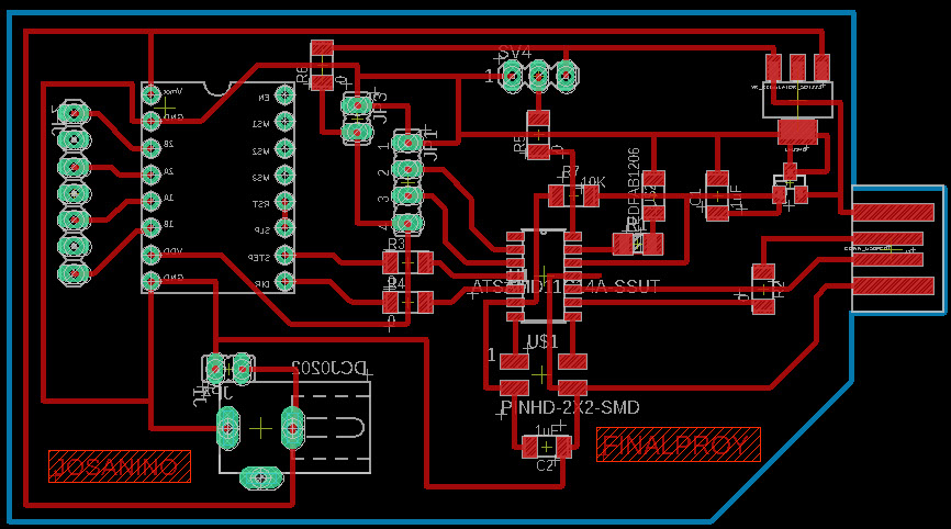
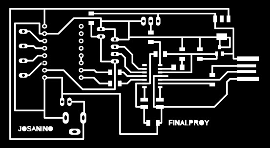
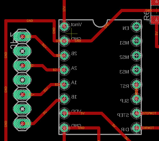
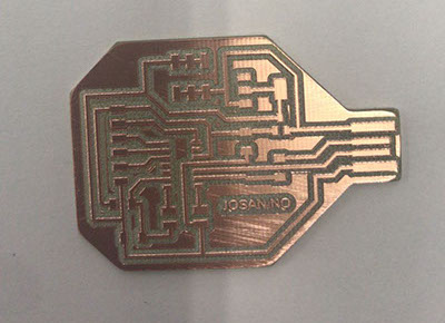
Image exported from Eagle software at 1200 dpi to be machined in Roland MDX 20 from mods software
Image exported from Eagle software at 1200 dpi to be machined in Roland MDX 20 from mods software

-crop-u44121.jpg?crc=362775821)
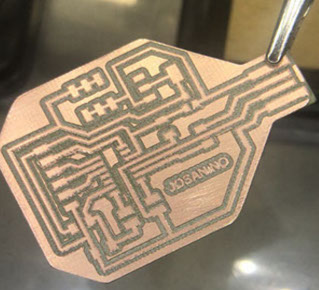
PCB Final Project sanded and ready to solder the electronic components
-crop-u44113.jpg?crc=4191215244)
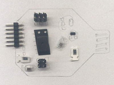
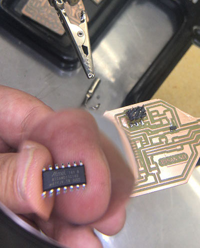
We present all the components before welding to verify that none are missing
-crop-u44128.jpg?crc=474898046)
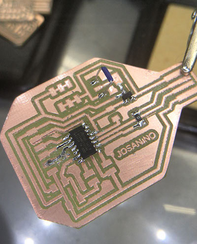
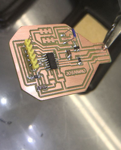
We started to weld with the microchip since it is the most delicate and difficult to weld in my opinion.
-crop-u44142.jpg?crc=330067559)
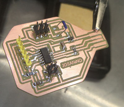
PCB front view with all soldered components
-crop-u44135.jpg?crc=3915716127)
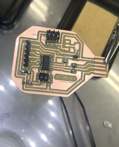
PCB seen from behind with all the components soldered and we decided to use some mounting brackets so that we can remove the pololu if we have to replace it in the future.
-crop-u44149.jpg?crc=490436429)
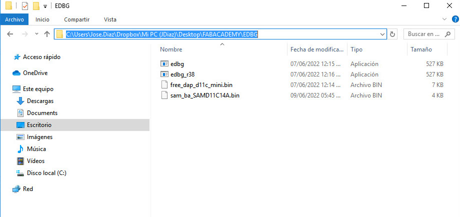
Once the pcb is ready with all the components, we program it with the help of another board and the Command Prompt program (Símbolo del sistema)
We locate in our system the EDBG folder
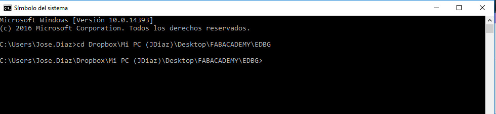
We change directory using cd space and then paste the address of the folder:
Dropbox\Mi PC (JDiaz)\Desktop\FABACADEMY\EDBG
We add the code we got from Adrian Torres' page at FAbLab Leon:
https://fabacademy.org/2020/labs/leon/students/adrian-torres/samdino.html#swd
Comando: edbg -ebpv -t samd11 -f sam_ba_SAMD11C14A.bin
NOTE: edbg It has to be the name of the program as it is in the folder (*.exe)
C:\Users\Jose.Diaz\Dropbox\Mi PC (JDiaz)\Desktop\FABACADEMY\EDBG>edbg -ebpv -t samd11 -f sam_ba_SAMD11C14A.bin
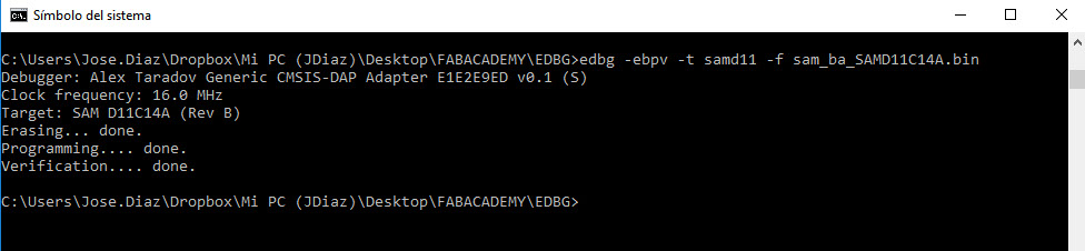
And everything is correct both programming and verification
Since we have it verified, we program it to start our engine. But before we check this programming guide with some important details to consider
====================================== ATsamD11C14A =====================================
Other COM PWM Analog INT Arduino* Arduino* INT Analog PWM COM Other
=========================================================================================
1-------------------
SCK*/RX2 TCC01 * * 5 | A5 A4 | 4 * * TCC00 MOSI*/TX2 REF
MOSI* TCC02 * 8 | A8 (XIN) A2 | 2 * * DAC
SCK* TCC03 * 9 | A9 (XOUT) Vdd |
SDA/MISO* TC10 * NMI 14 | A14 Gnd |
SCL/SS* TC11 * * 15 | A15 A25 | 25 USB/DP
BOOT 28 | A28/RST A24 | 24 USB/DM
SWDCLK TX1/MISO* 30 | A30 A31 | 31 * RX1/SS* SWDIO
-------------------
* Most pins can be used for more than one function. When using PIN_MAP_STANDARD, the port
pin number printed on the chip above is also used in Arduino (but without the 'A') for
all of the supported functions (ie: digitalRead(), analogRead(), analogWrite(), etc.).
When using PIN_MAP_COMPACT, the Arduino numbering is sequential starting from 0 at the
top left pin (A5). PIN_MAP_COMPACT uses less FLASH.
* When USB CDC is enabled, Serial refers to SerialUSB, otherwise it refers to Serial1.
* When using ONE_UART_NO_WIRE_ONE_SPI, use SPI on pins 4, 5, 14, and 15.
When using NO_UART_ONE_WIRE_ONE_SPI, use SPI on pins 8, 9, 30, and 31.
* Tone available on TC2. TC2 is not routed to pins in the D11C14A.
* Leave pin A30 floating (or use external pullup) during reset.
* DO NOT connect voltages higher than 3.3V!
We open the arduino software and in the tools menu we select the port with which it recognized our card COM13 (MattaiTech Xeno Mini)
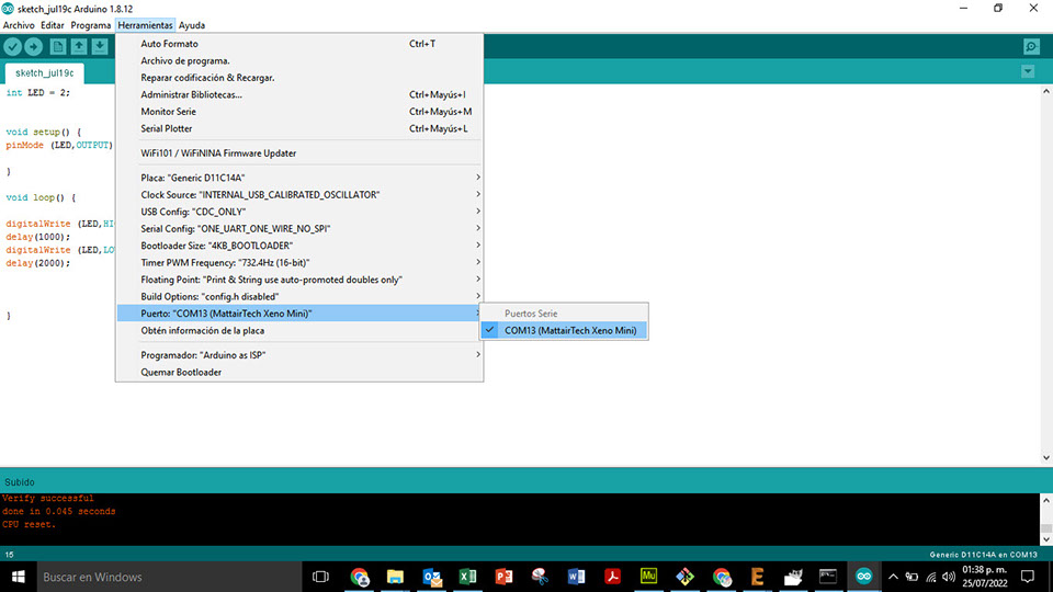
We load the code to the card from the Arduino software
const int dirPin = 15; //direction pin
const int stepPin = 14; //pwm pin
const int ledpin = 2; //led probe
int stepDelay = 750; // vel motor
void setup() // configuration global
{
pinMode(dirPin, OUTPUT); //output direction pin
pinMode(stepPin, OUTPUT); // outpur pwm pin
pinMode(ledpin, OUTPUT); // output led probe
}
void loop()
{
digitalWrite(ledpin,HIGH); //turn on led probe
digitalWrite(dirPin, LOW); //direction mot (HIGH spin left and LOW spin right)
digitalWrite(stepPin, HIGH); //four lines generate pwm
delayMicroseconds(stepDelay);
digitalWrite(stepPin, LOW);
delayMicroseconds(stepDelay);
}

Ready loaded and working
Additional Information
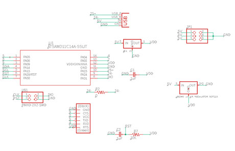
For this assignment, the first and necessary thing was to design the card to program. The samdino card was taken as a base and a new option called Josanino was developed.
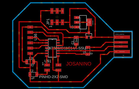
Redesigned in eagle software
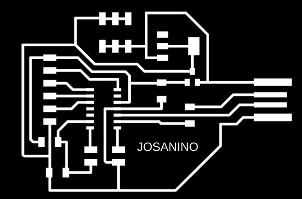
It is saved in two images to be able to machine it, one is to make the traces and the other is to cut the contour of the plate.

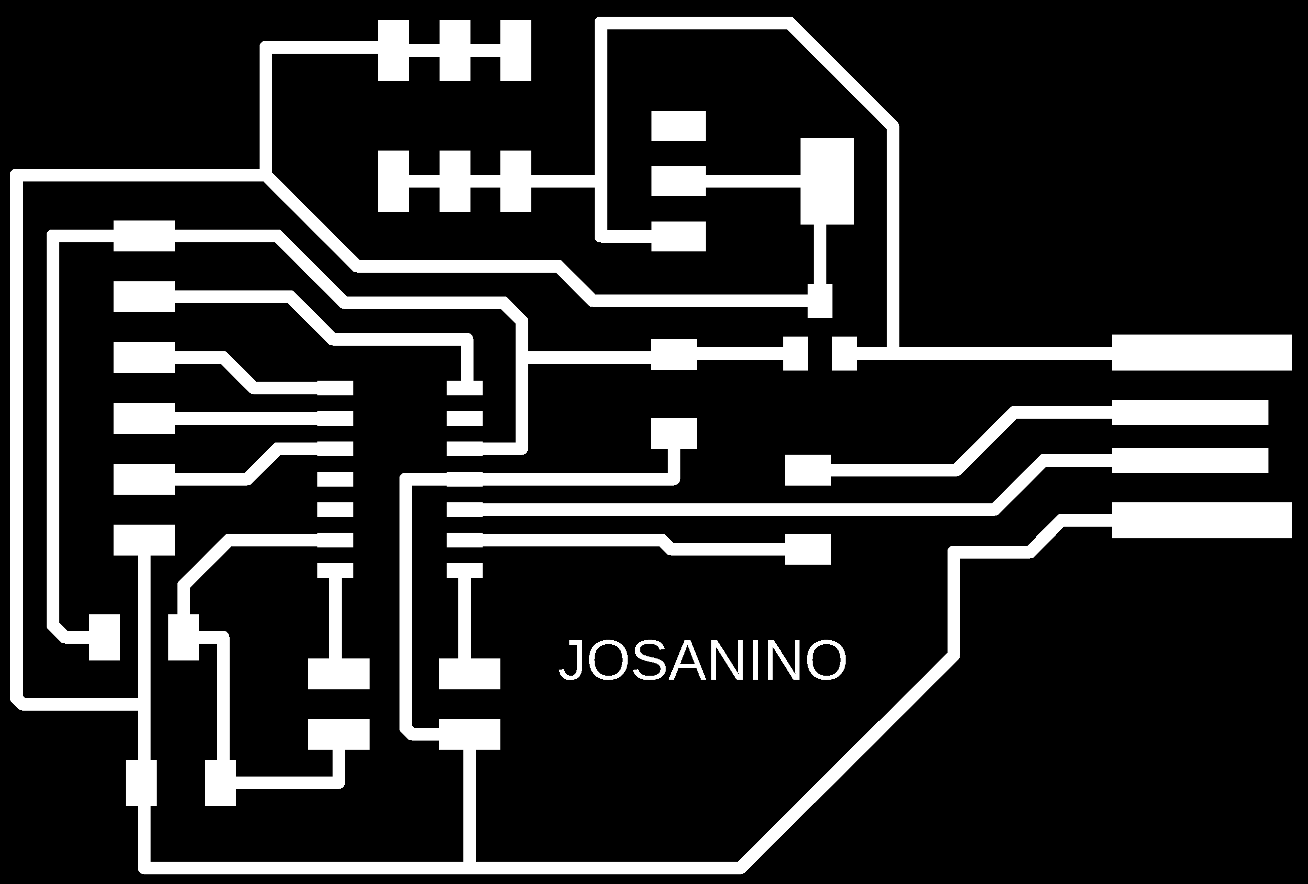
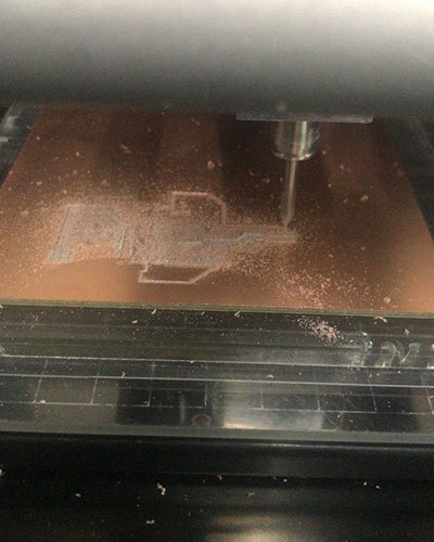

Milling is sent to the roland MDX 20 opareda from the mods software. To know step by step of this operation you can consult the assignmnet Electronics Production where it is explained in detail.

Sanded and ready to start welding the components
Capacitor 10 uF
Regulador 3.3 -0.1 A
AT SAMD IIC
Programmable header for our card
Header
Capacitor 10 uF
Resistor 0 OHMS
Resistor 10k OHMS
Jumper