group assignment:
probe an input device's analog levels and digital signals
https://fabacademy.org/2022/labs/ciudadmexico/cdmx_input-devices.html
individual assignment:
measure something: add a sensor to a microcontroller board
that you have designed and read it
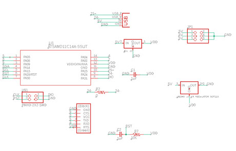
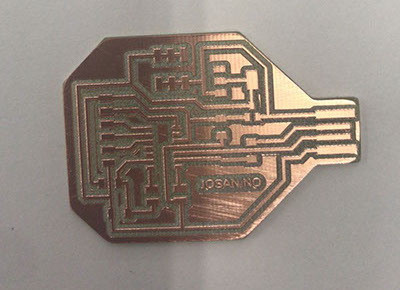
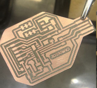
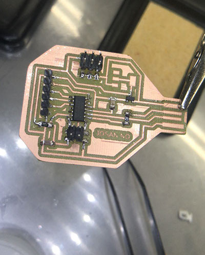
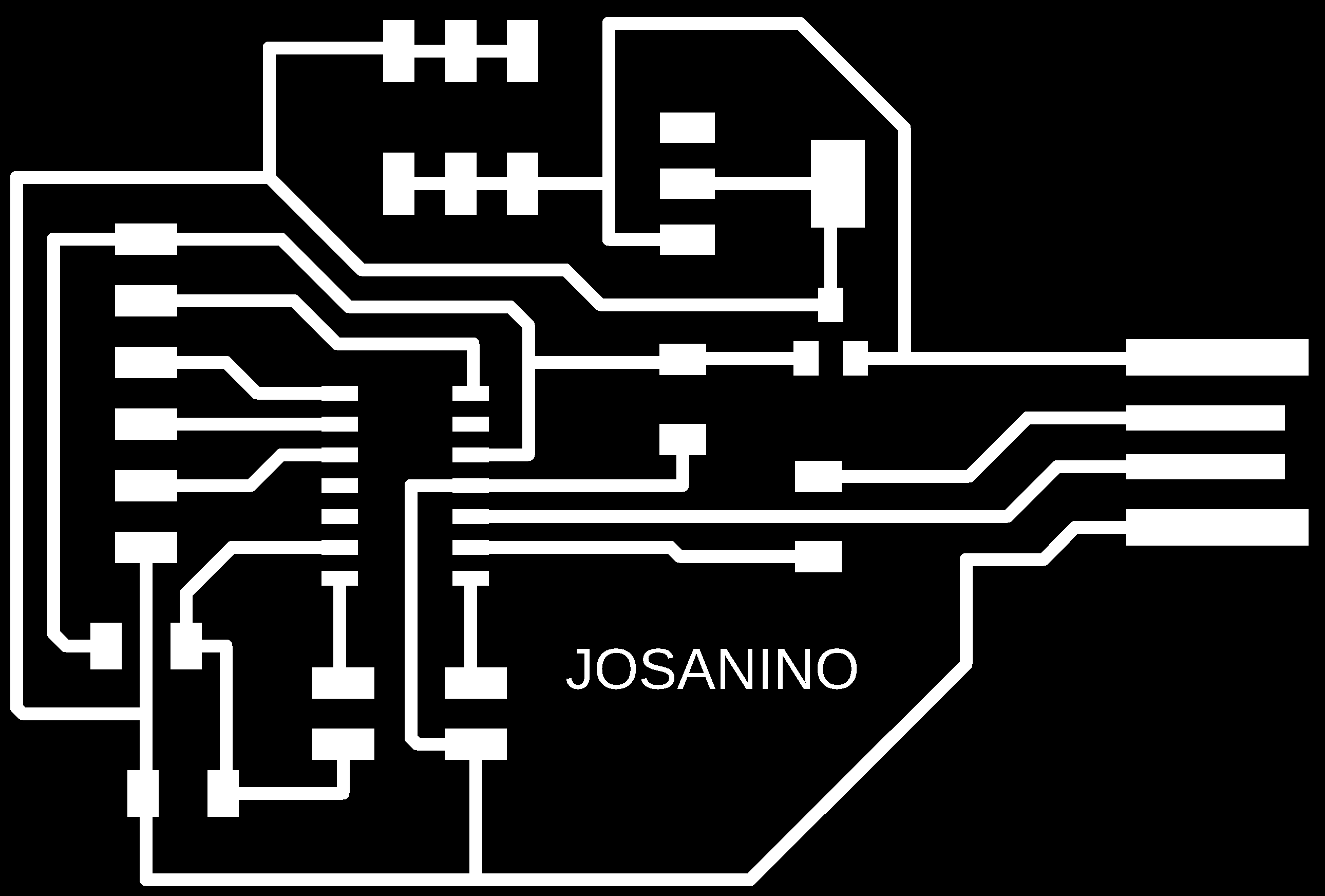
For this assignment, the first and necessary thing was to design the card to program. The samdino card was taken as a base and a new option called Josanino was developed.
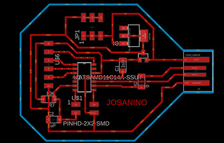
Redesigned in eagle software
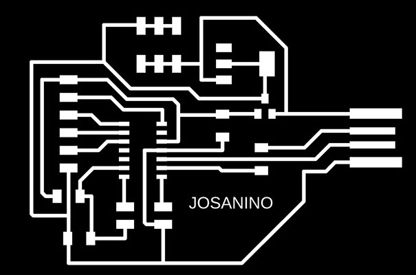
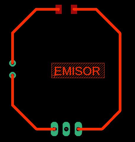
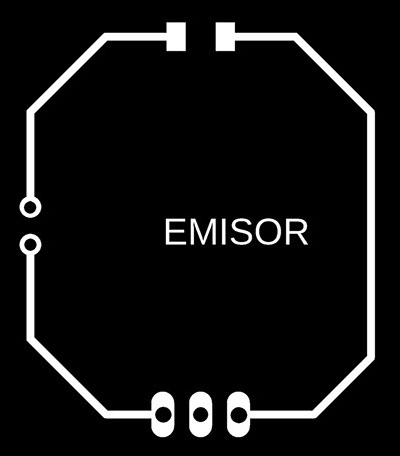
It is saved in two images to be able to machine it, one is to make the traces and the other is to cut the contour of the plate.

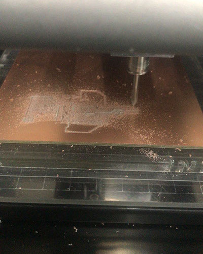
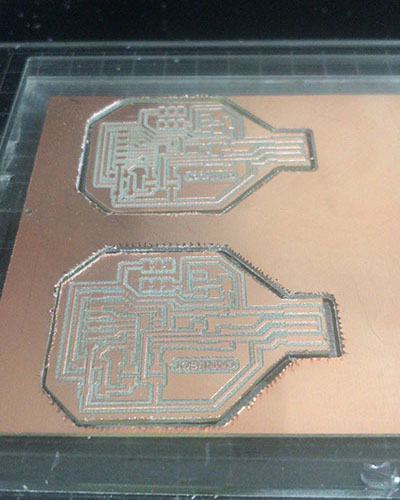
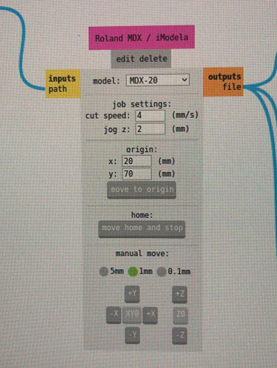
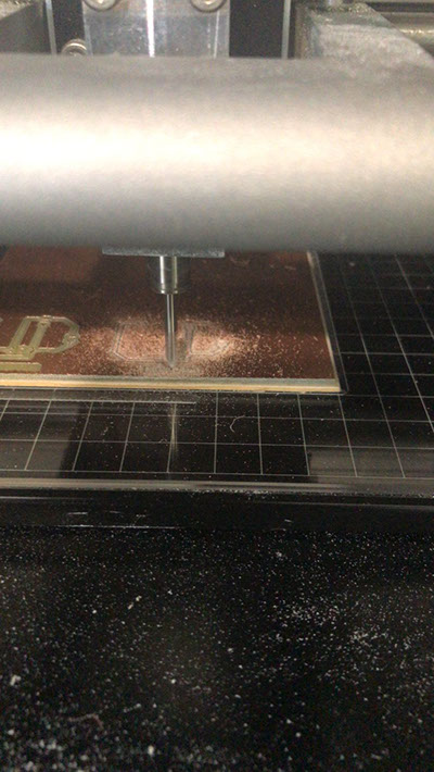
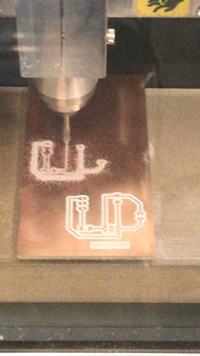
Milling is sent to the roland MDX 20 opareda from the mods software. To know step by step of this operation you can consult the assignmnet Electronics Production where it is explained in detail.
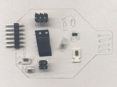

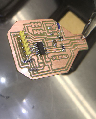
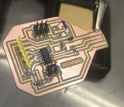
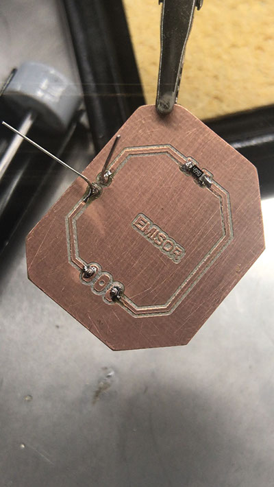
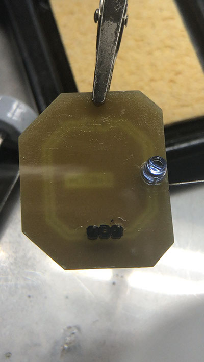
Sanded and ready to start welding the components
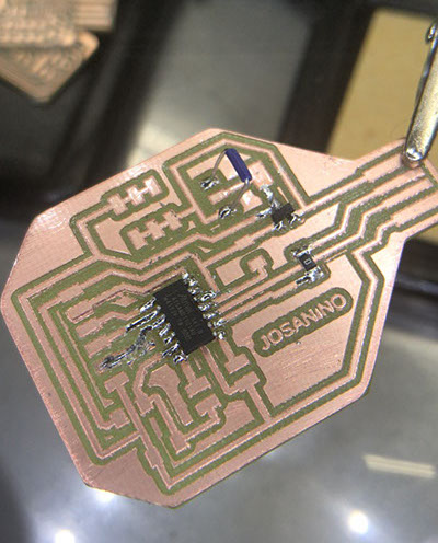
Capacitor 10 uF
Regulador 3.3 -0.1 A
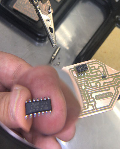
AT SAMD IIC
Programmable header for our card
Header
Capacitor 10 uF
Resistor 0 OHMS
Resistor 10k OHMS
Jumper
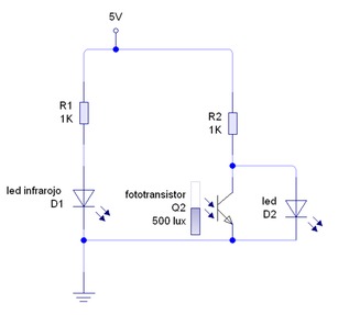
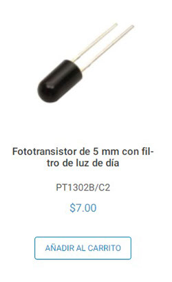
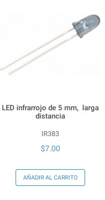
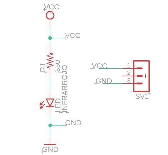
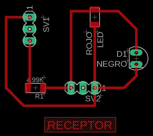
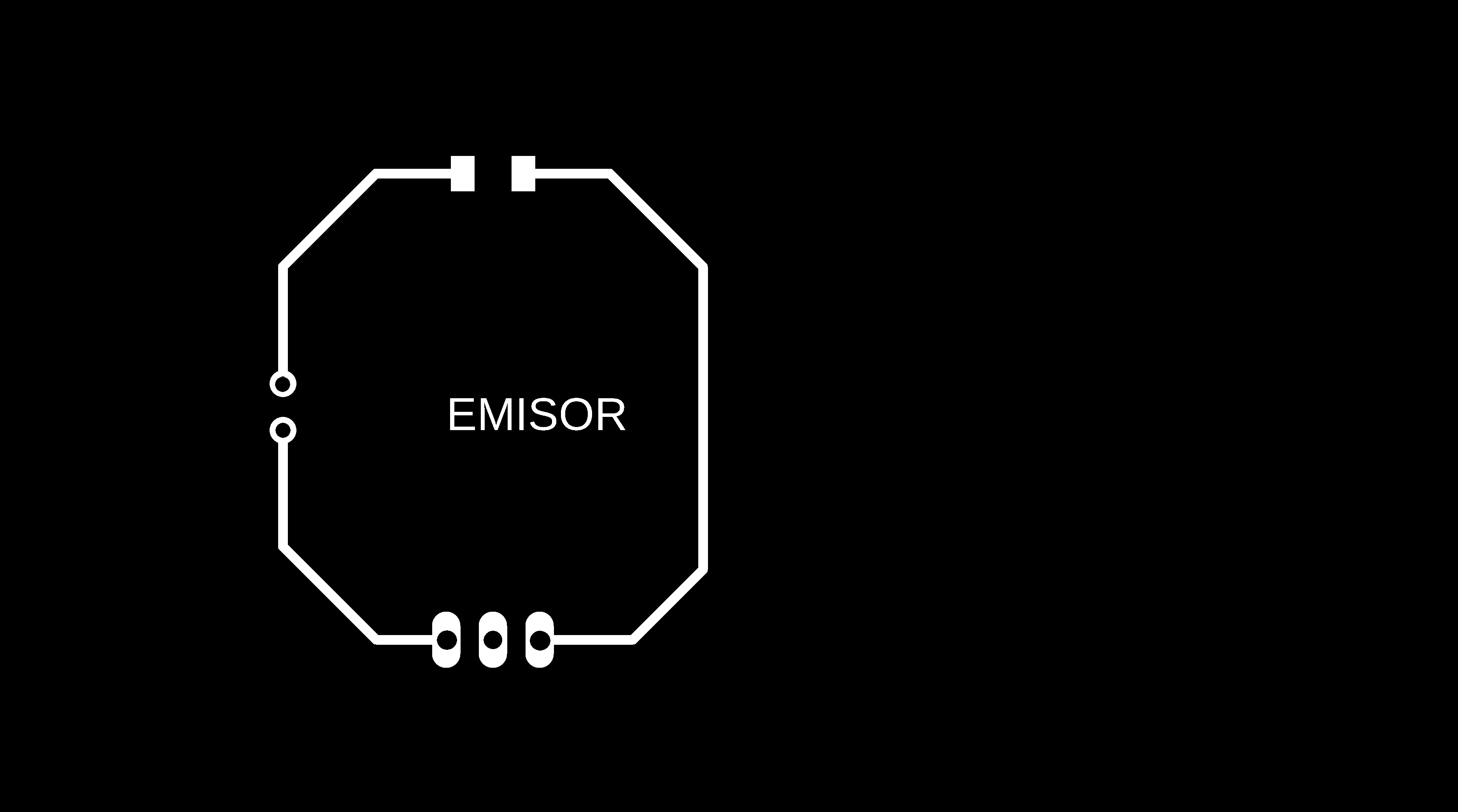
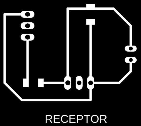
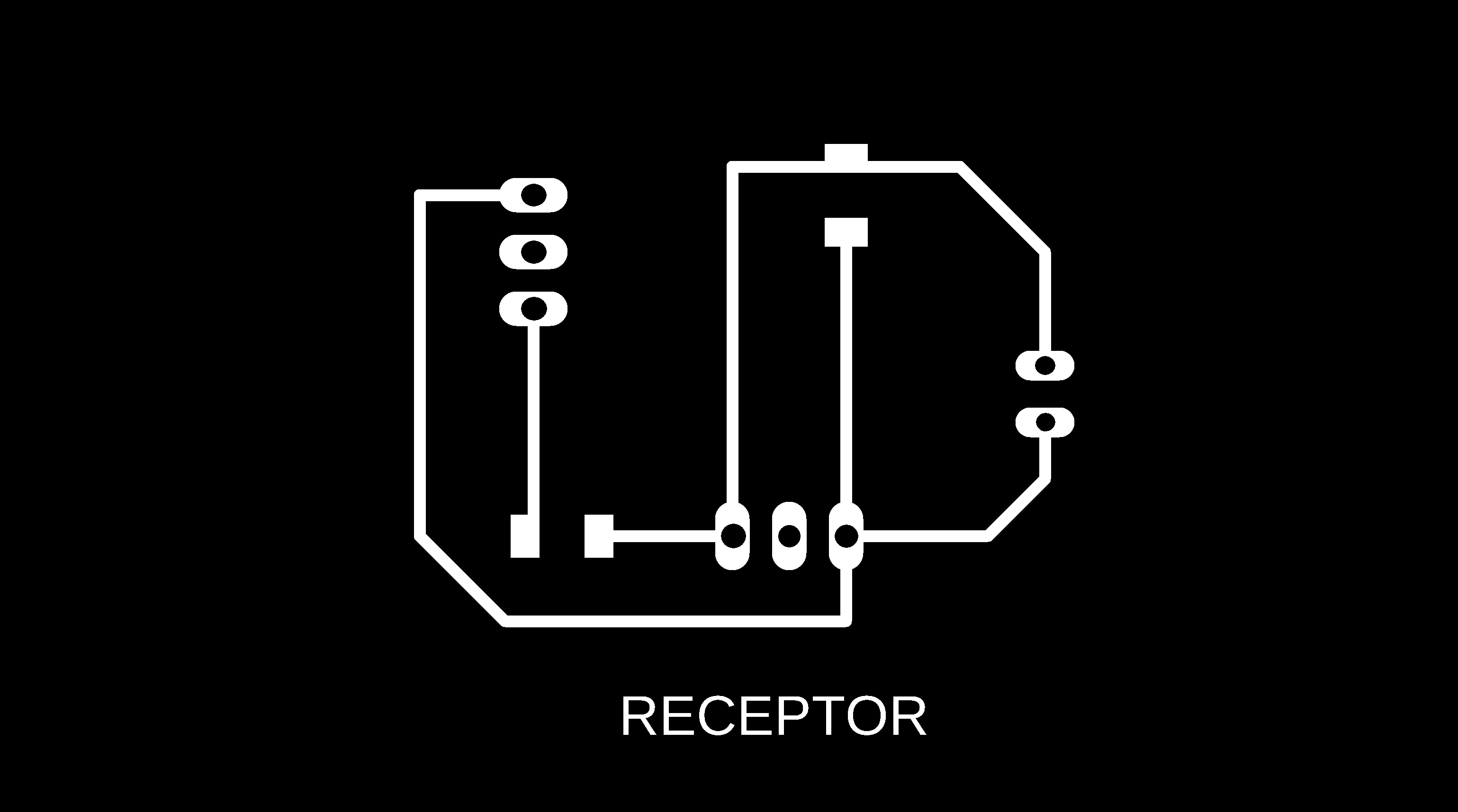
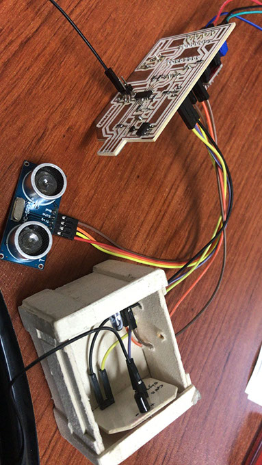
For this assignment I decided to use the phototransistor sensors that I will use later in my final project. We start based on this connection diagram, the plates for the phototransistor sensor were made, said sensor will be used to stop the servomotor that the machine to be designed will have.


Milling on the Roland MDX 20 machine from the mods software
-crop-u43071.jpg?crc=469191886)
-crop-u43079.jpg?crc=4004203679)
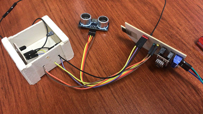
The sensor test was done to measure the necessary distance for the ball to fit in the final project and also to know if the type of ball material cut the sensor signal
-crop-u43086.jpg?crc=4000034583)
-crop-u43093.jpg?crc=209843423)
The test was also done with the ball covered with transparent PET to test if the signal passed through the PET and was interrupted when the ball was placed.
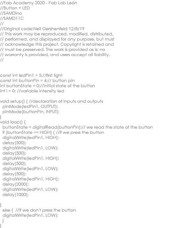
We use this code to program Josanino and connect the transmitter and receiver of the sensor already with the appropriate distance between them so that the ball would fit and cut the signal and turn on the LED
-crop-u43121.jpg?crc=193347659)
-crop-u43114.jpg?crc=528965583)
Without the ball the LED stays off
With the ball the LED lights up
.jpg?crc=3791796520)
const int dirPin = 15; //direction pin
const int stepPin = 14; //pwm pin
const int ledpin = 2; //led probe
int sensor = 4;
const int EchoPin = 9;
const int TriggerPin = 8;
int stepDelay = 12500; // vel motor
int signalsensor;
void setup() // configuration global
{
Serial.begin(115200);
pinMode(dirPin, OUTPUT); //output direction pin
pinMode(stepPin, OUTPUT); // outpur pwm pin
pinMode(ledpin, OUTPUT); // output led probe
pinMode(TriggerPin, OUTPUT);
pinMode(EchoPin, INPUT);
pinMode(sensor, INPUT); // input signal sensor
}
void loop()
{
digitalWrite(ledpin,HIGH); //turn on led probe
int cm = ping(TriggerPin, EchoPin);
Serial.print("");
Serial.println(cm);
if (cm >30 && cm<50)
{
//digitalWrite(ledpin,LOW);
digitalWrite(dirPin, LOW); //direction mot (HIGH spin left and LOW spin right)
digitalWrite(stepPin, HIGH); //four lines generate pwm
delayMicroseconds(stepDelay);
digitalWrite(stepPin, LOW);
delayMicroseconds(stepDelay);
signalsensor = digitalRead(sensor);
if (signalsensor = 1)
{
digitalWrite(ledpin,HIGH);
delay(1000);
digitalWrite(ledpin,LOW);
delay(1000);
digitalWrite(ledpin,HIGH);
delay(1000);
digitalWrite(ledpin,LOW);
}
}
}
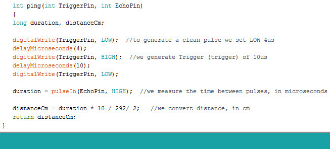
int ping(int TriggerPin, int EchoPin)
{
long duration, distanceCm;
digitalWrite(TriggerPin, LOW); //to generate a clean pulse we set LOW 4us
delayMicroseconds(4);
digitalWrite(TriggerPin, HIGH); //we generate Trigger (trigger) of 10us
delayMicroseconds(10);
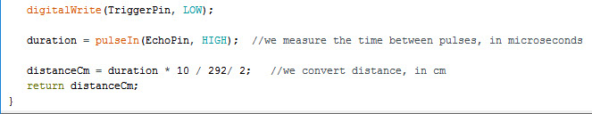
digitalWrite(TriggerPin, LOW);
duration = pulseIn(EchoPin, HIGH); //we measure the time between pulses, in microseconds
distanceCm = duration * 10 / 292/ 2; //we convert distance, in cm
return distanceCm;
}
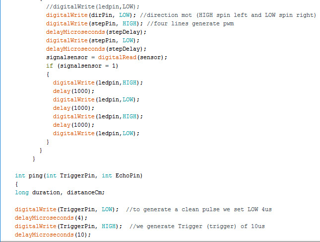
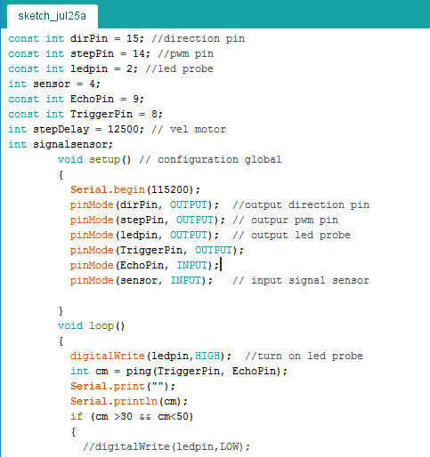
In this code I already used the final projet board where I will integrate a motor, an ultrasonic sensor and a phototransistor sensor. The motor already moves according to the characteristics that I need for the final project
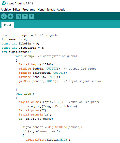
const int ledpin = 2; //led probe
int sensor = 4;
const int EchoPin = 9;
const int TriggerPin = 8;
int signalsensor;
void setup() // configuration global
{
Serial.begin(115200);
pinMode(ledpin, OUTPUT); // output led probe
pinMode(TriggerPin, OUTPUT);
pinMode(EchoPin, INPUT);
pinMode(sensor, INPUT); // input signal sensor
}
void loop()
{
digitalWrite(ledpin,HIGH); //turn on led probe
int cm = ping(TriggerPin, EchoPin);
Serial.print("");
Serial.println(cm);
if (cm >30 && cm<50)
{
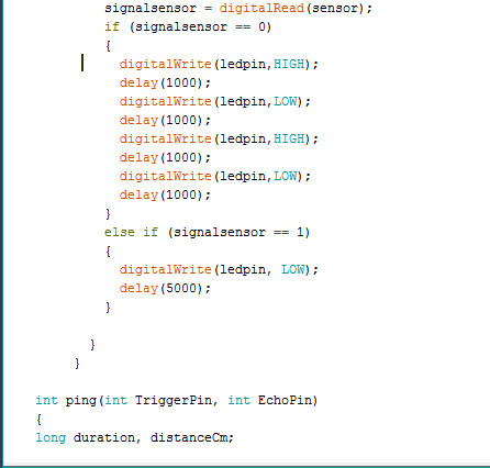
signalsensor = digitalRead(sensor);
if (signalsensor == 0)
{
digitalWrite(ledpin,HIGH);
delay(1000);
digitalWrite(ledpin,LOW);
delay(1000);
digitalWrite(ledpin,HIGH);
delay(1000);
digitalWrite(ledpin,LOW);
delay(1000);
}
else if (signalsensor == 1)
{
digitalWrite(ledpin, LOW);
delay(5000);
}
}
}
int ping(int TriggerPin, int EchoPin)
{
long duration, distanceCm;
digitalWrite(TriggerPin, LOW); //to generate a clean pulse we set LOW 4us
delayMicroseconds(4);
digitalWrite(TriggerPin, HIGH); //we generate Trigger (trigger) of 10us
delayMicroseconds(10);
digitalWrite(TriggerPin, LOW);
duration = pulseIn(EchoPin, HIGH); //we measure the time between pulses, in microseconds
distanceCm = duration * 10 / 292/ 2; //we convert distance, in cm
return distanceCm;
}
With this code the connection of the ultrasonic sensor that measures the distance at which an object is located was made, it was programmed to be in a range of 30 cm to 50 cm when the object is outside this range the sensor sends the distance and The Led on the board stays on, as the object falls within the programmed range (here it was set at approximately 40 cm), the Led changes and starts blinking and the ultrasonic sensor marks the distance. The phototransistor sensor is at the right distance for the ball to cut the transmission and thus brake the motor; We will see this on the final project page
Final PCB project was developed in output device
Phototransistor sensor emitter and receiver boards developed in this assignment whose function will be to stop the motor when the ball falls for the final project