Assignment 3
Computer -
Controlled Cutting
group assignment:
characterize your lasercutter's focus, power, speed, rate,
kerf, and joint clearance and types
https://fabacademy.org/2022/labs/ciudadmexico/cdmx_cutting.html
individual assignment:
cut something on the vinylcutter
design, lasercut, and document a parametric construction kit,
accounting for the lasercutter kerf,
which can be assembled in multiple ways,
and for extra credit include elements that aren't flat
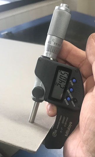
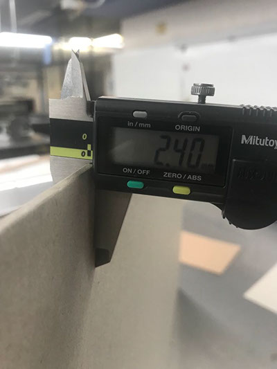
The measurement of the thickness of the material to be cut was taken, which in this case was gray cardboard.
.jpg?crc=90369217)
-crop-u35146.jpg?crc=3983151819)
Calculate the distance from the lens to the material to be cut
.jpg?crc=501205879)
.jpg?crc=4281094894)
The test was made varying both the speed and the power of the laser.
.jpg?crc=67336013)
.jpg?crc=4144246901)
.jpg?crc=3911150249)
The test was carried out varying both the speed and the power of the laser, concluding that for engraving on gray cardboard the ideal is speed 4 power 40 and for cutting speed 4 power 70.
.jpg?crc=43299999)
.jpg?crc=4028002646)
The Kerf test gave us the result that the cut is 1 mm per side, which in this case results in 2 mm of perforation in relation to what was traced in the digital file.
.jpg?crc=3986457984)
.jpg?crc=3772096801)
lasercut

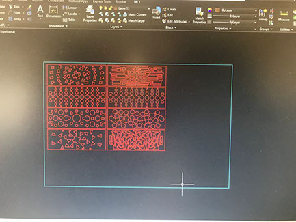
Pattern plotting in Rhino software and exported as DXF for machining from autocad software
.jpg?crc=50145642)
.jpg?crc=4088461538)
With the power 95% and speed 1.8% parameters, the 3 mm thick mdf is cut
.jpg?crc=3896382311)
With an approximate time of 3 minutes of cutting for each patternr
.jpg?crc=279318599)
.jpg?crc=3798309393)
8 different patterns were cut in a total of approximately 25 minutes
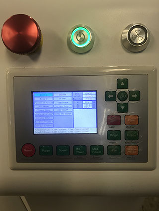
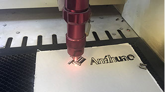
For this assignment I also used another laser machine that we have at the university. The brand is Bodor the size of the work area is 90 cm x 120 cm

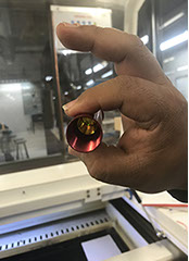

Checking the type of mirror and lens measurement to calibrate the focal length between the lens and the material, which in this case is 2.5 cm
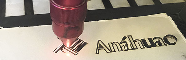
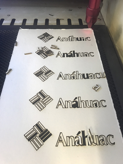
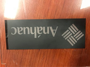
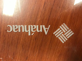
The Anahuac University logo was tracing to do the cutting tests measuring power and speed

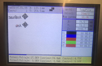


Several tests were made combining the power of the laser with the speed or velocity of movement.
Velocity .............................................. % of Power
20 mm/s .............................................. 98 %
40 mm/s .............................................. 80 %
60 mm/s .............................................. 70 %
80 mm/s .............................................. 70 %
100 mm/s ............................................ 50 %
Several tests were made combining the power of the laser with the speed or velocity of movement.
Velocity .............................................. % of Power
20 mm/s .............................................. 40 %
40 mm/s .............................................. 30 %
60 mm/s .............................................. 20 %
80 mm/s .............................................. 10 %
100 mm/s ............................................ 0.5 %
Finally the best velocity and % power:
for cutting: vel. 80 mm/s & 70 % power
for ingraving: vel. 40 mm/s & 30 % power
For this exercise cardboard for models was used 2mm width


vinylcutter

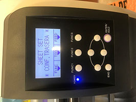
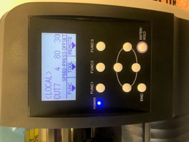
The plotter used to cut vinyl is a brand Mimaki 120 cm in lenght. The material is loaded from the back aligned with the guide lines so that it is straight.
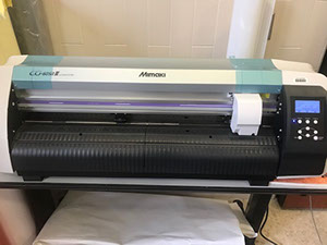
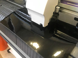


Once the material is loaded, the pressure of the blade is adjusted locally and later the cut is sent from the computer via remote

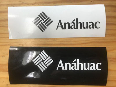
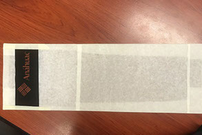

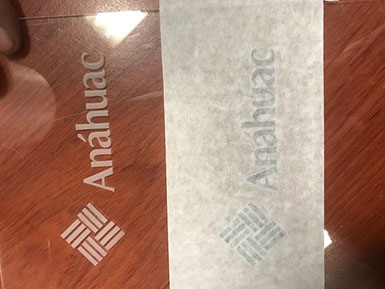
Logo cut in positive and negative
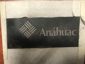
Negative logo glued on acrylic to be sandblasted
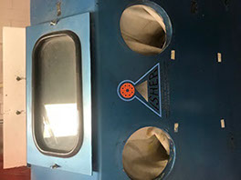
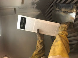
Once the logo was cut, it was glued to a transparent acrylic to be subjected to the sandblast machine and make a frosted effect
logo sandblasted with transfer paper
logo sandblasted without transfer paper
logo sandblast effect final result
logo sandblast effect final result and positive effect logo vinyl cutting
finally the result was a logo in positive another in negative and the acrylic sandblasted
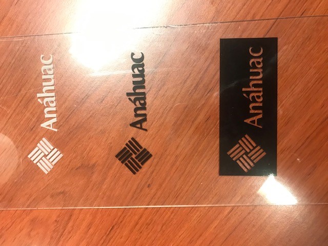
draft effect
positive effect
sandblast efect
For this exercise, it was modeled in Rhino grasshopper to parameterize the figure and it can be manipulated, adapting it to the thickness of the required material and assemble perfectly, always considering the kerf of the machine, which was 0.5 mm to form the sculpture.

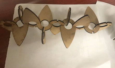

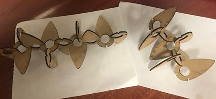
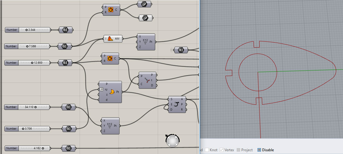
The part was parameterized in rhino grasshopper and we can control the inner radii, upper outer radius, lower outer radius, the tip, and the notches where the part is assembled and we can adjust according to the thickness required by the material

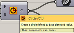
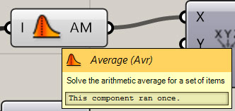
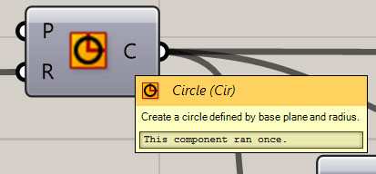
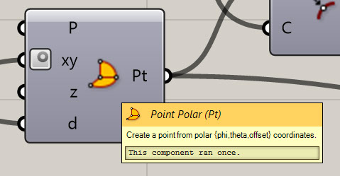
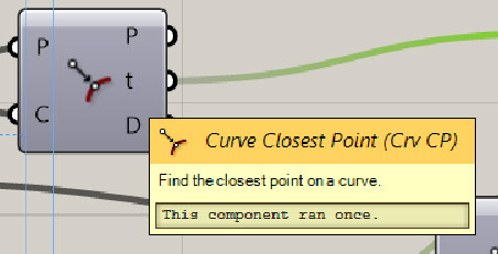
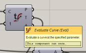
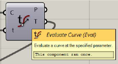
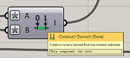
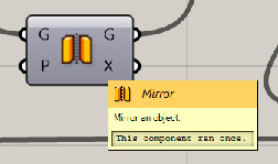
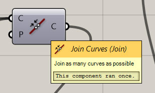
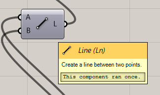
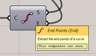
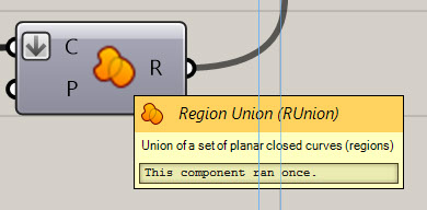
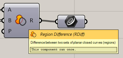
Here we see the rhino grasshopper interface and all the and the connection network of the components to form the part and make it parametric. I describe below the name of each component used within the programming
controls the thickness of the material
control the inner radius
controls the top outer radius of the part

controls the length of the piece
controls the bottom radius of the part
controls the radius of the nose of the part