Group Assignment – Computer controlled cutting - CDMX
General objective (group assignment):
- Characterize your lasercutter's focus, power, speed, rate, kerf, and joint clearance
- Document your work to the group work page and reflect on your individual page what you learned.
GCC LaserPro Spirit GLS
Technical characteristics
- Work area: 860 x 610 mm
- Table Size: 1025 x 705 mm
- Maximum Speed: 80 IPS
- Focus Lens: 2 in.
- Resolution: 125 – 1500 DPI
- Laser 30 to 100 W 10.6 µm
- Voltage:
-
- 100-240 V Under 80 W
- 240 V Above 80 W
Development
Cardboard
To characterize the laser cutter, we made a test with different speeds and power for both, cutting and engraving.
To set a starting point, we used the actual speeds and power that our fablab uses for each of the materials being tested, moving from there in different directions to get the most efficient setting for that material.
For the corrugated cardboard, those initial settings were as follows:

From there, we made tests, changing the parameters in different directions to find an optimum setting:

The results were as follows:

The steps we followed were:
1. Our partners in Fablab Queretaro made a vectorized image of the Fablab logo. They are using it to make the same tests for their machines.

2. Using these images, we made our own test sheet, standardizing the tests that were going to be made in Fablab Mexico City.

3. To adjust the parameters into the plotting software, we needed to establish different colors for the different speed and power settings, our machine has the ability to use as many as 16 colors with different settings for each color. But to make the test easier, we only used the first 7 colors, repeating the process for the next batch of parameters.
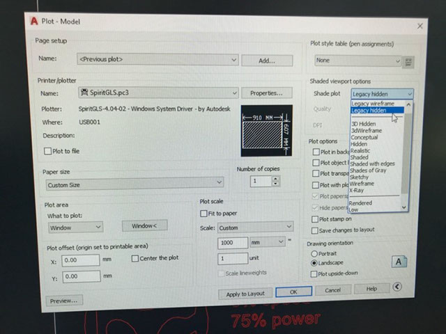
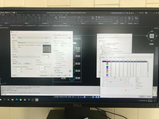
4. The software is embedded into Autocad’s plotting menu, and to get there you must go through the following windows:
a. Plot menu:

b. Then, in the Printer/Plotter area, choose our machine (Spirit GLS) and click on Properties which will open the Plotter Configuration Editor (middle window). Then, you should click on custom properties, which will prompt the Properties window (front window):

c. Inside the Properties window, you can change the parameters as needed, the columns’ functions are:

5. Once the parameters were set, you can proceed to your cutting job.

Kerf
To parametrize the Kerf, we started by measuring the cardboard to be used to define where our test should start. The average thickness was around 4 mm (3.96 mm). So, the test would take this into account and revolve around this number.

We prepared a test sheet for numbers around the measured thickness:

And continued with the cutting process:

Getting to the conclusion that our machine has a kerf of 0.05 mm on each side. So, if we need something to have a perfect press-fit we need to adjust for the lasercutter kerf in 0.1 mm.
Gray cardboard
To parametrize the Kerf, we started by measuring the cardboard to be used to define where our test should start. The thickness was around 2.40 .So, the test would take this into account and revolve around this number.
We prepared a test sheet for numbers around the measured thickness:

We prepared a test sheet for numbers around the measured thickness:
.jpg?crc=3963683250)
And continued with the cutting process:
.jpg?crc=3856183651)
Getting to the conclusion that our machine has a kerf of 0.05 mm on each side. So, if we need something to have a perfect press-fit we need to adjust for the lasercutter kerf in 0.1 mm. As the images shown.
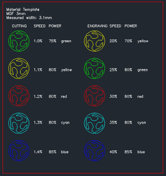
MDF 3 mm
To parametrize the Kerf, we started by measuring the cardboard to be used to define where our test should start. The thickness was around 2.40 .So, the test would take this into account and revolve around this number.
For cutting 3mm MDF the optimum parameters are:
• Speed: 1.2%
• Power: 80%
• PPI:400
For Engraving, the optimum parameters are:
• Speed: 30%
• Power: 80%
• PPI:400
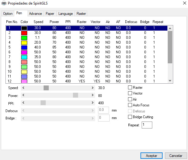
This the graphic interface for the machine. You have to check “vector” in order to cut.
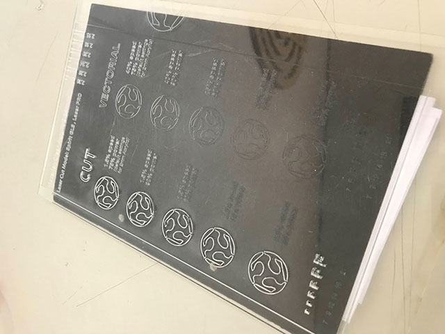
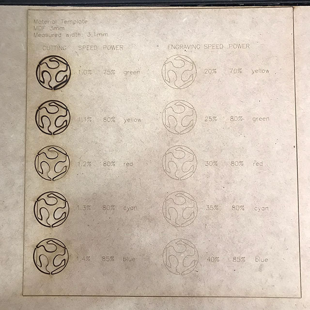
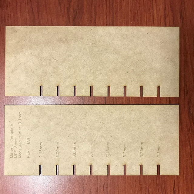
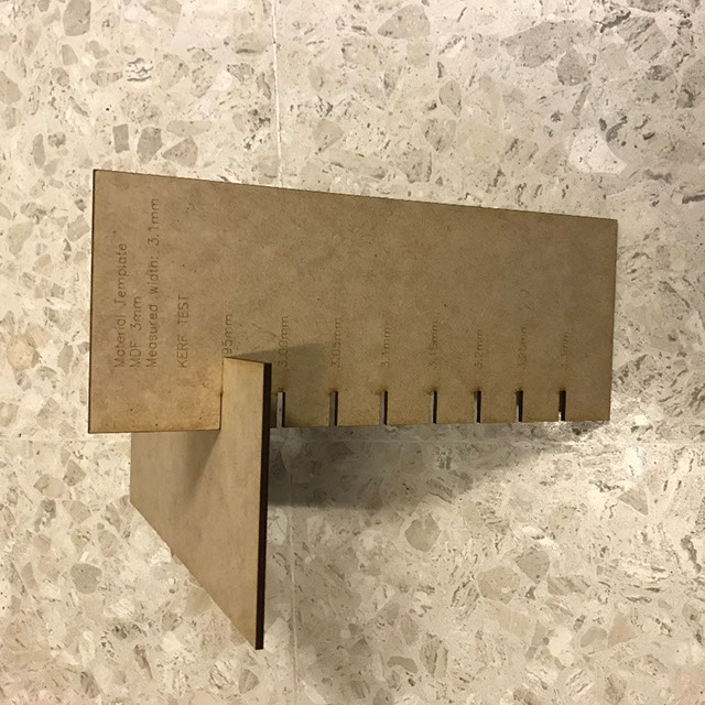
This is the cut template.
MDF Kerf test
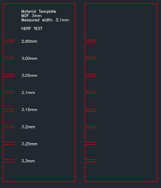
I measured the material and it is 3.1mm Therefore, I cut increments of 0.05mm up and down. It turned out that the best fit was 2.95mm. I think that when I initially measured it, the material had a small burr, that made it look like it was 3.1, because after laser cutting the measure was 2.9. In any case, for this material, the ideal kerf is 2.95.
Crystal Clear Acrylic 2mm thickness
Cut and engrave
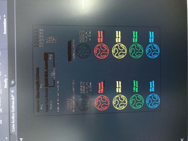
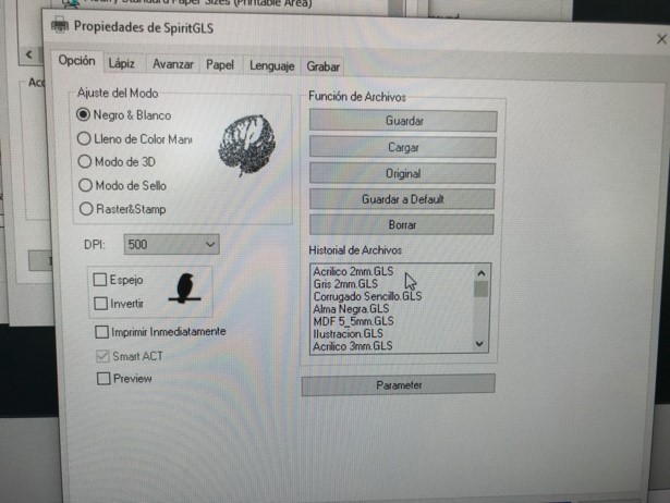
In the plot window, go over the “properties” button, there choose the material, in this case was Acrylic 2mm GLS.Each color layer has a different setup of speed and power so, in your drawing, you need to choose the layer/color for each drawing or text if you want it to be cut or just engrave, here we use a different layers to see the differences between each setup but the default settings are: CUT1.5speed75% power ENGRAVE (vectorial)40% speed75% power