Jose Alegria - Fab Academy
![]()
![]()
![]()
![]()
Output
Devices
Assignment
wHAT iS THE ASSIGNMENT ABOUT?
Add an output
device to a microcontroller board you ve designed and
program it to do something.
Group
Assignment:
Measure
the power consumption of an output device
1st Step.
Electronics design
Using the same board I designed
for electronics design, I made a few changes:
-
Removed the extra button and LED
-
Added input and output pins to be able to connect and
disconnect several peripherals to the board.
-
Added 5V, 3.3 V and GND pins to be able to send
signals to peripherals.
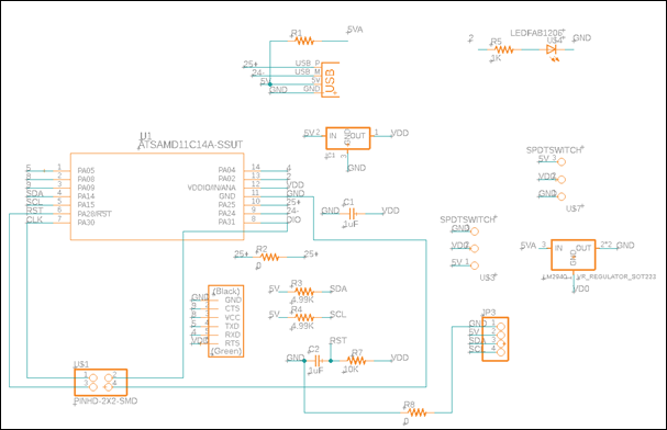
For this assignment, I
attached a photo interrupter to get an input device and a buzzer as an output
device. The photo interrupter is going to be connected to the 3.3V, GND and Pin
4. The buzzer will be connected to the pin 4 and GND.
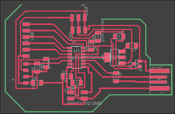
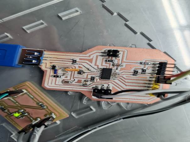
Here is the final board:
2nd Step.
Electronics production
The process to make the electronics
board is explained in this assignment:
3rd Step. Code and
programming
The process to program a board is explained in this
assignment:
To operate the output device, I had to tell the
microprocessor where the input and output devices are going to be installed,
that is the first part of the code I am going to use:
const int ledPin1 = 2;
const int buzzer = 9;
const int buttonPin
= 4;
Then I had to tell it the function that they will be
doing:
void setup() {
pinMode(ledPin1,
OUTPUT);
pinMode(buzzer,
OUTPUT);
pinMode(buttonPin, INPUT);
When that setup is done, then you can start telling
the microprocessor what you want to be done and when:
void loop() {
pos = digitalRead(buttonPin);
if (pos != pos_guardada)
{
pos_guardada
= pos;
cambio++;
Serial.print("Numero de cambios: ");
Serial.println(cambio);
t1 = millis();
}
if (millis()-t1>tiempo_lluvia) { cambio = 0;
}
if (cambio>2) {
lluvia = 1;
t2 = millis();
}
else { lluvia
= 0;
}
if (lluvia==1)
{
digitalWrite(ledPin1,
HIGH);
i =
0;
do
{
digitalWrite(buzzer,
HIGH);
delay(500);
digitalWrite(buzzer,
LOW);
delay(500);
i++;
} while (i
< 10);
}
else {
digitalWrite(ledPin1,
LOW);
digitalWrite(buzzer,
LOW);
}
}
Here, I am telling the microprocessor when I want the
buzzer to start working (HIGH) and when to stop (LOW). I also wrote that the
LED should turn on when the buzzer is working, but that is an extra that does
not count toward this assignment.
This is a video of the board working as intended.
Conclussions
This assignment is the first one to
show us how to tell the microprocessor what to do and when, the most difficult
part was writing the code and there were most of the problems that emerged,
they were solved by making small changes in the code to translate from the
logic we are used to think with and the logic needed to program a processor.
Original
Files
1.
Code File
Nueval
Checklist
-
Linked to the group
assignment page
-
Documented how you determined power
consumption of an output device with your group
-
Documented what you learned from
interfacing output devices to microcontroller and controlling the devices.
-
Described your design and fabrication
process o r linked to previous examples.
-
Explained the programming processes
you used.
-
Outlined problems and how you fixed
them.
-
Included original design files and
code.
-
Included a hero shot or video of your
board.
2022