Workflow of assignment
Electronics Design
To design any electronic circuit, either analog or digital, we need to be able to predict the voltages and currents at all the places within the circuit.
Simple circuits may be designed by connecting a number elements or functional blocks such as intrgrated circuits. But more complex digitals circuits(with SMD component) are typically designed with the aid of computer software.
PCB Design (Eagle)
I used to Eagle to design the board, the software was easy to use and look really neat. It wasn't my first time with design PCB, but earlier I had designed PCB for though-hole components and never checked my circuit by the Design rules.
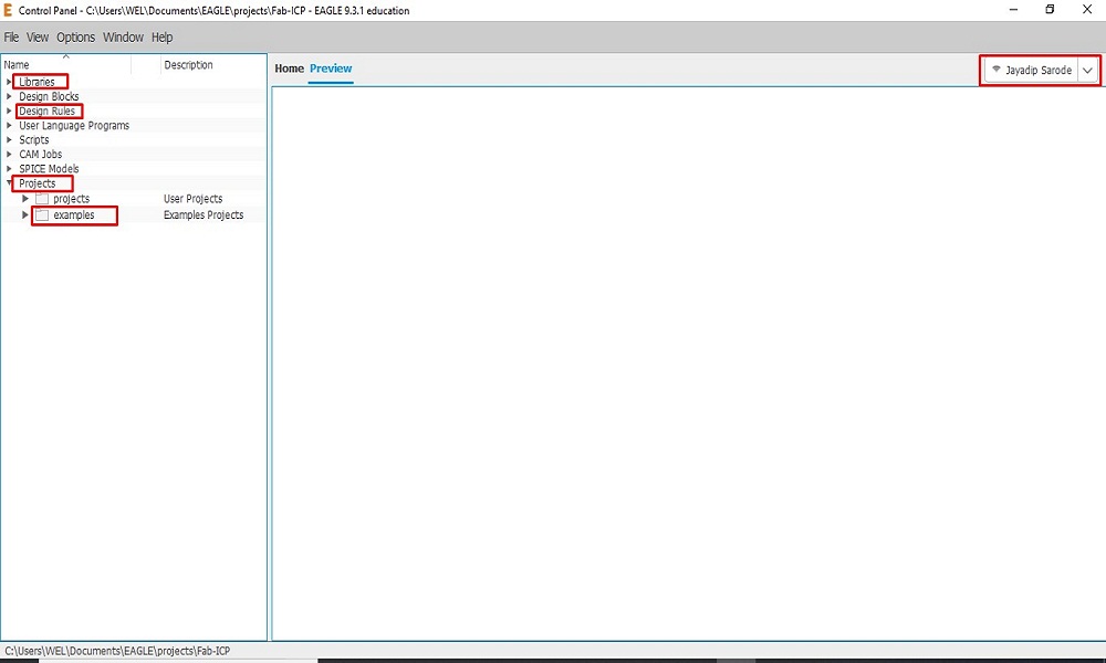
I download the Autodesk_Eagle_Student_Version. This is control panel of Eagle. here is a various control parameters like Libraries, Design rules, Projects, Examples etc.
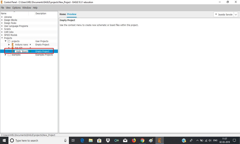
Created a new project "Hello-Board".
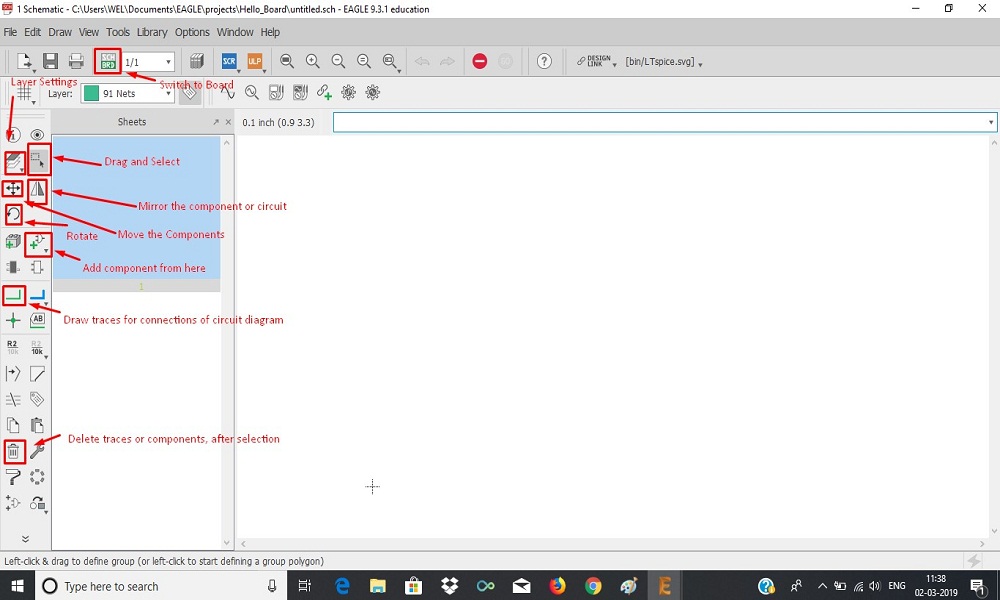
Most common uses feature functions in Eagle for design.
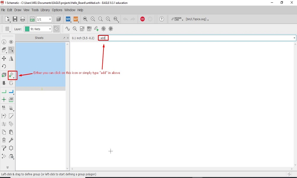
We can add component both ways in Eagle from library.
Fab_Academy Library Installation (Eagle)
First thing I did was to go and download the fabacademy libraary (fab.lbr). Once the library was downloaded I add it to my Eagle library.
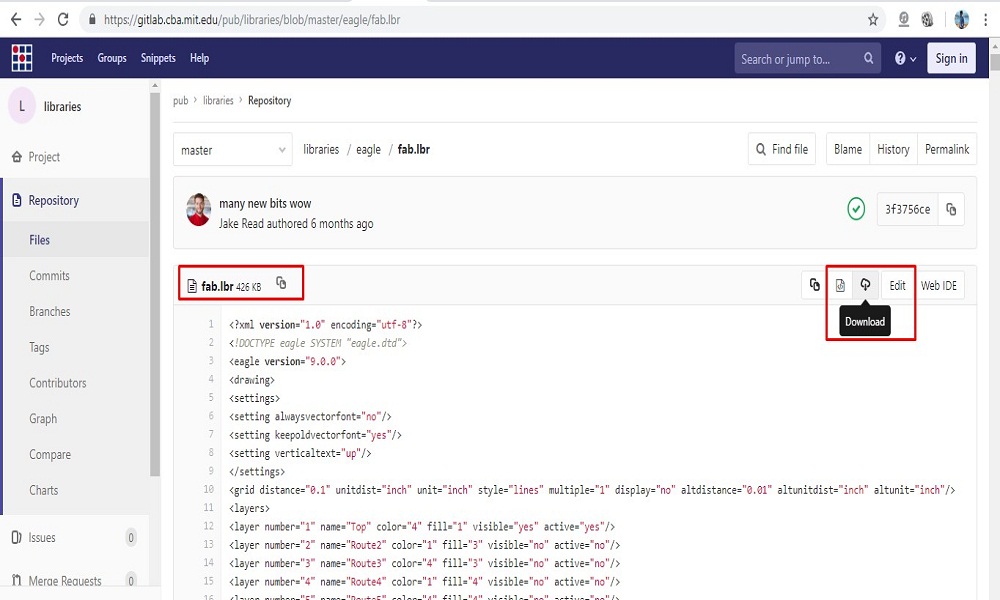
fabacademy libraary (fab.lbr) downloaded from Github
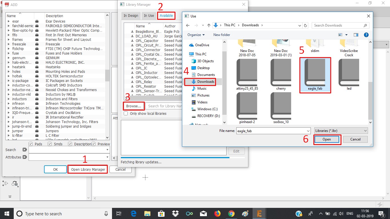
Installation Procedure
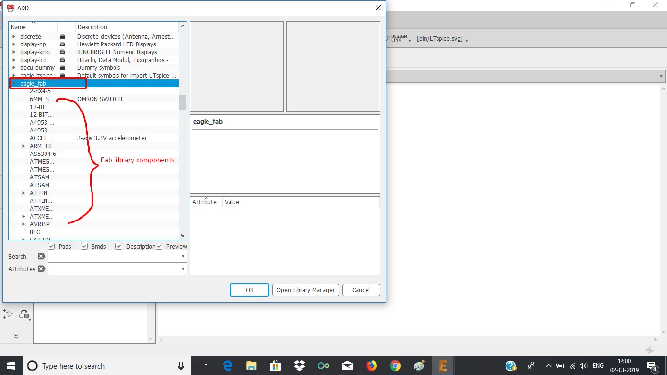
Checked in Eagle library after completing installation procedure.
Design Process
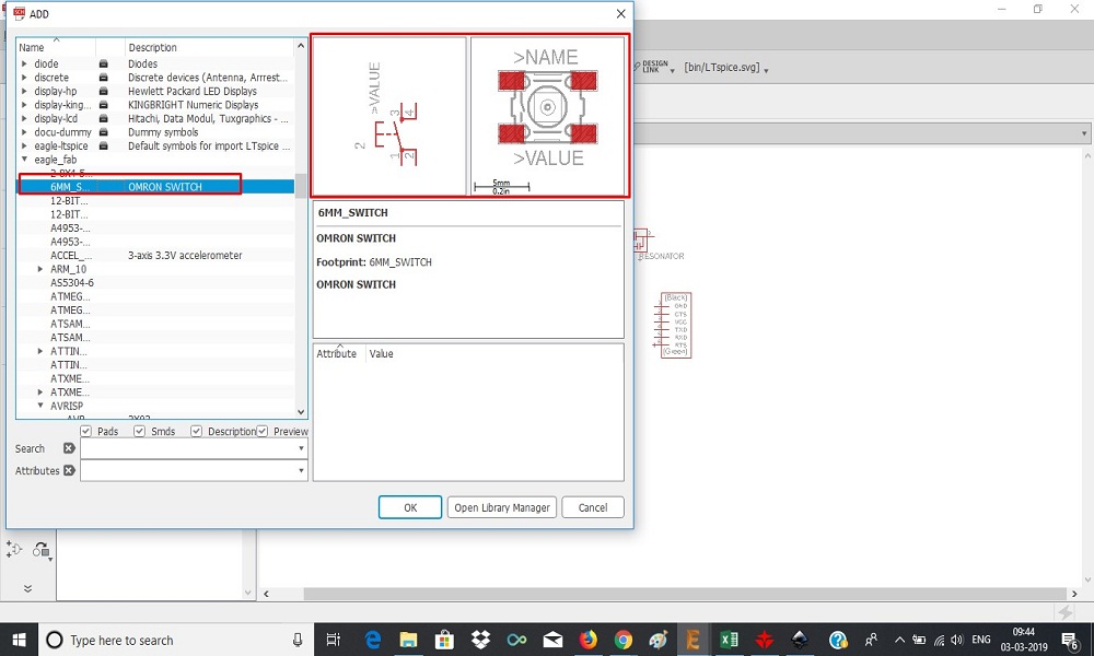
After loading the library I went inside it using the add command and import every component I needed for my board. I add 2 led and 2 switches extra. Resonator and button from the basic components of the helloboard as shown below:
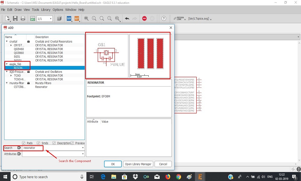
Resonator
After adding all components, I connected components in schematic as per circuit diagram.
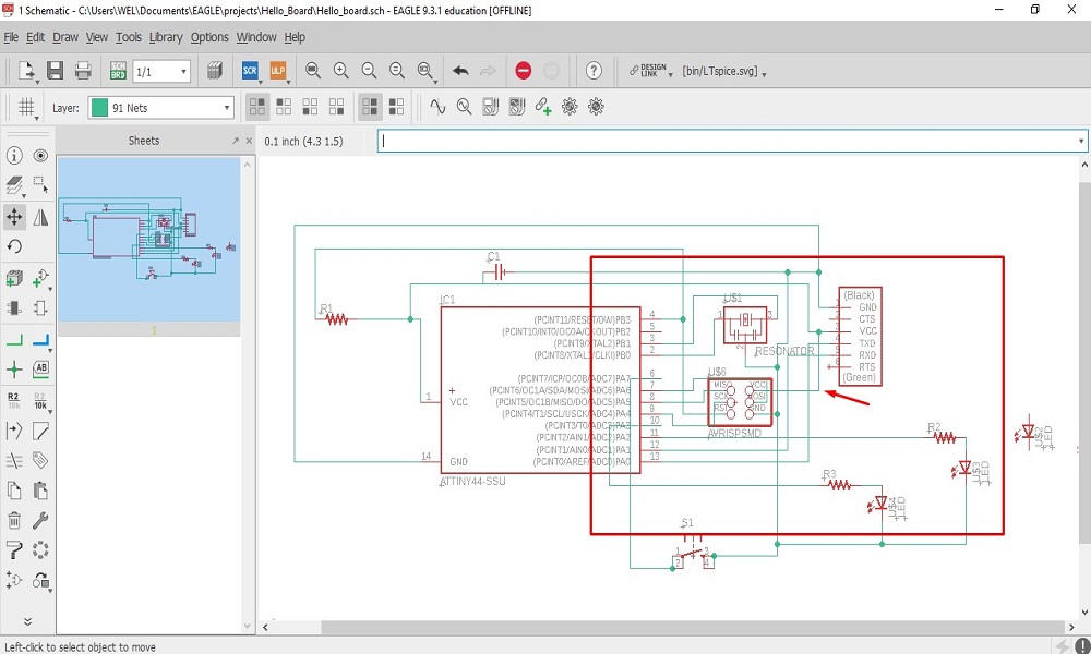
After connection, some tacks cross-over, it is not problem to create board. But it not looks good to see. So I choose another features for connections i.e. Lebel
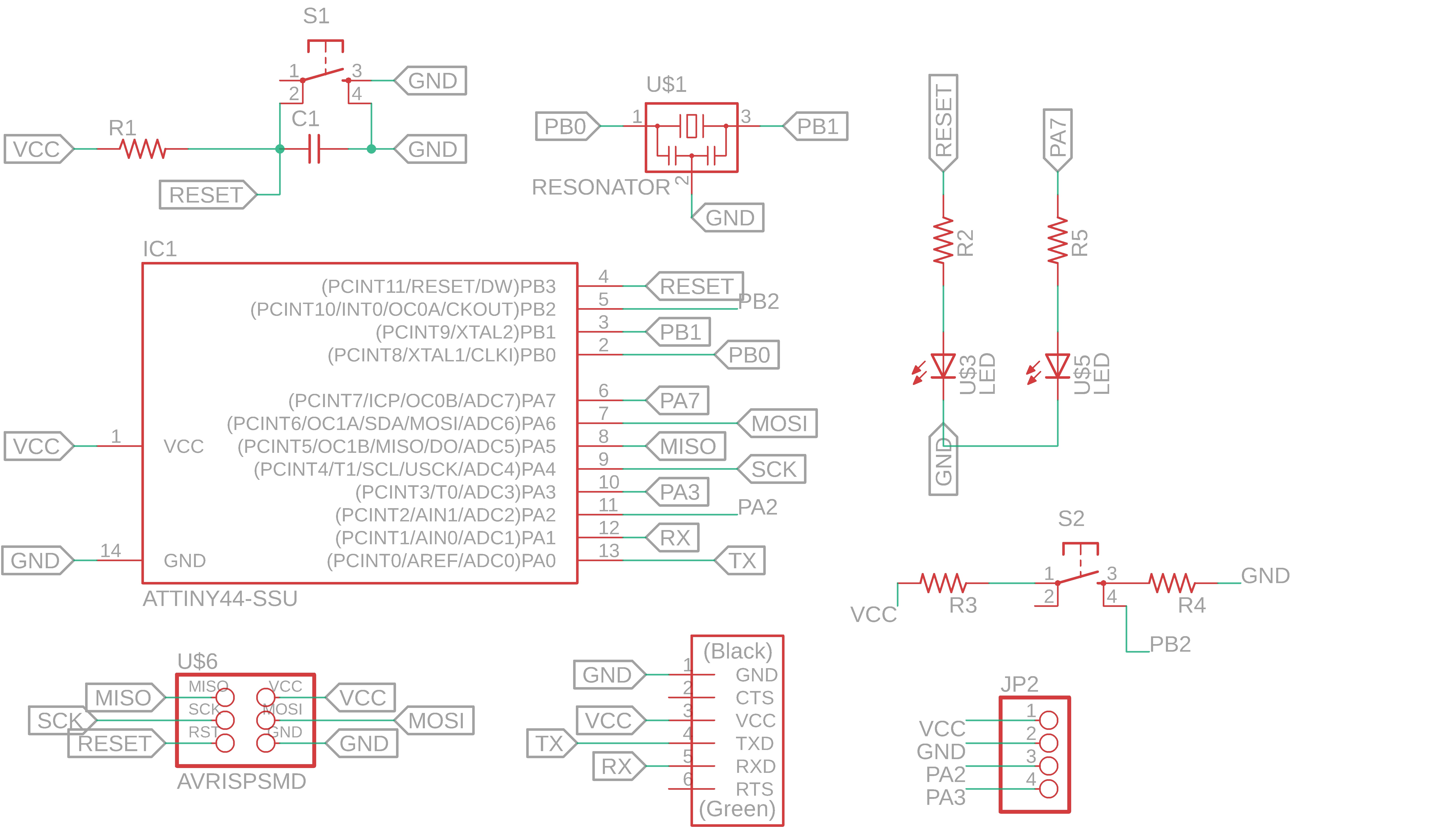
I also added 4-pin connector for VCC,GND and 2 pins of controller. It will be helps in "input and output devices" week. Finally at this stage Circuit Diagram is completed.
Open the DRC check from the file menu .
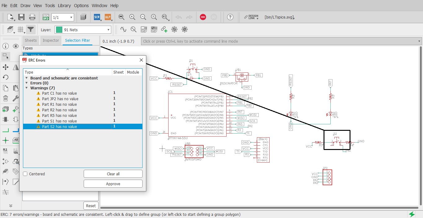
After running the DRC check. It generates either warnings, errors and some errors which can be approved are also. In my hello world board there were some warnings, I approved them. There were no any error in board.
Once completed circuit diagram connections, I choose "Switch to Board" option shown below:
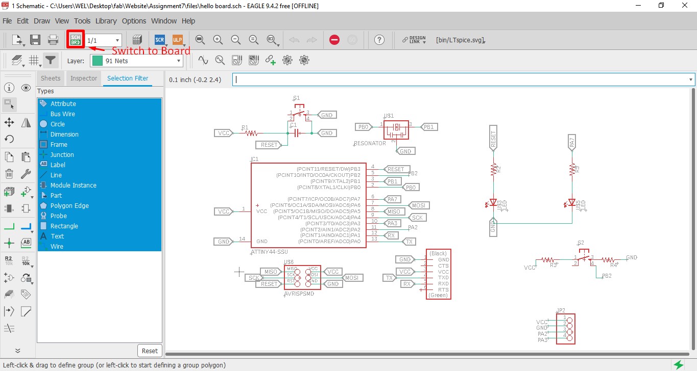
Everything was messed up after choosing "Switch to Board" option, but it was all there.
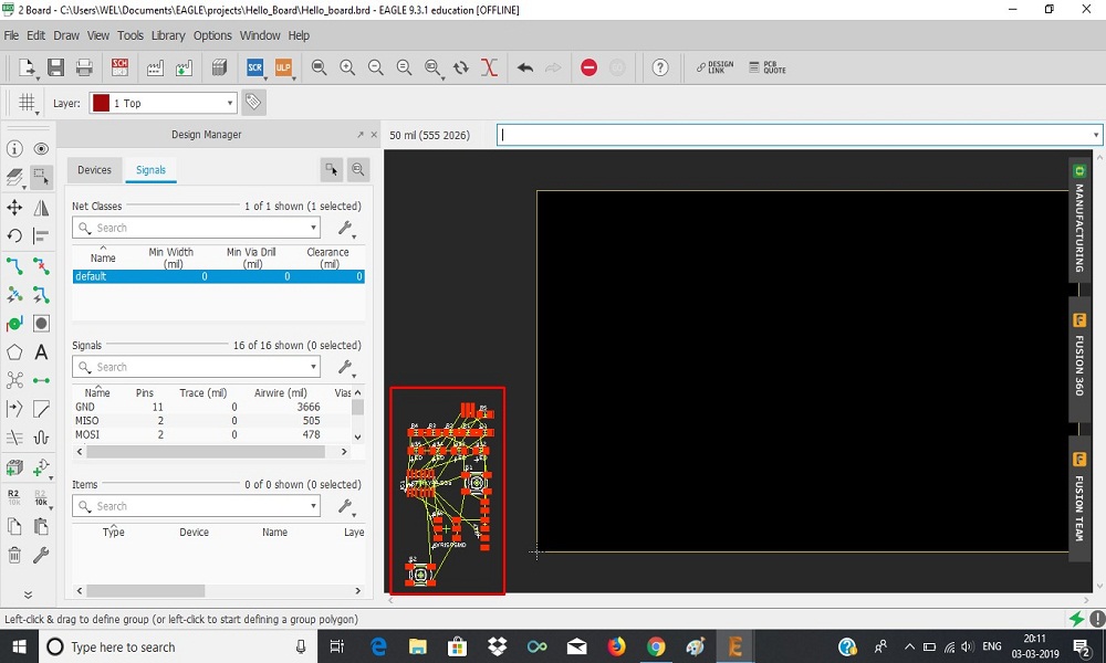
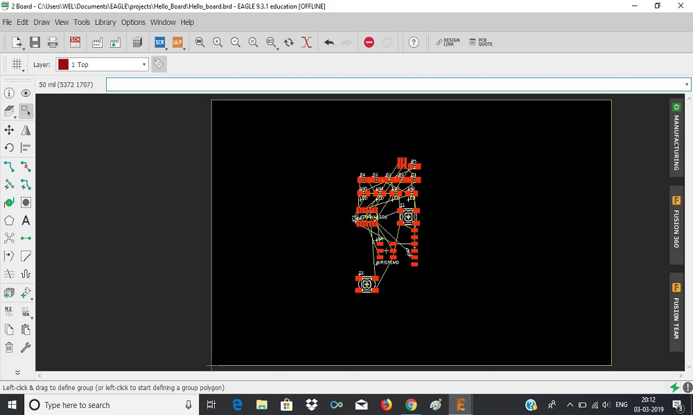
Select all components drang in the box.
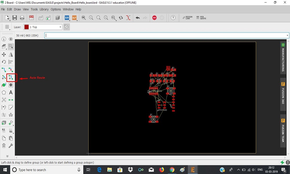
Then first I select the "Auto Route" option, but some some tracks were still blue. That mean I needed to make double-sided pcb, that's why I decided to make manual routing.
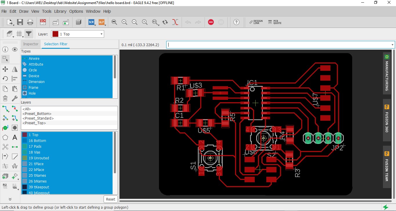
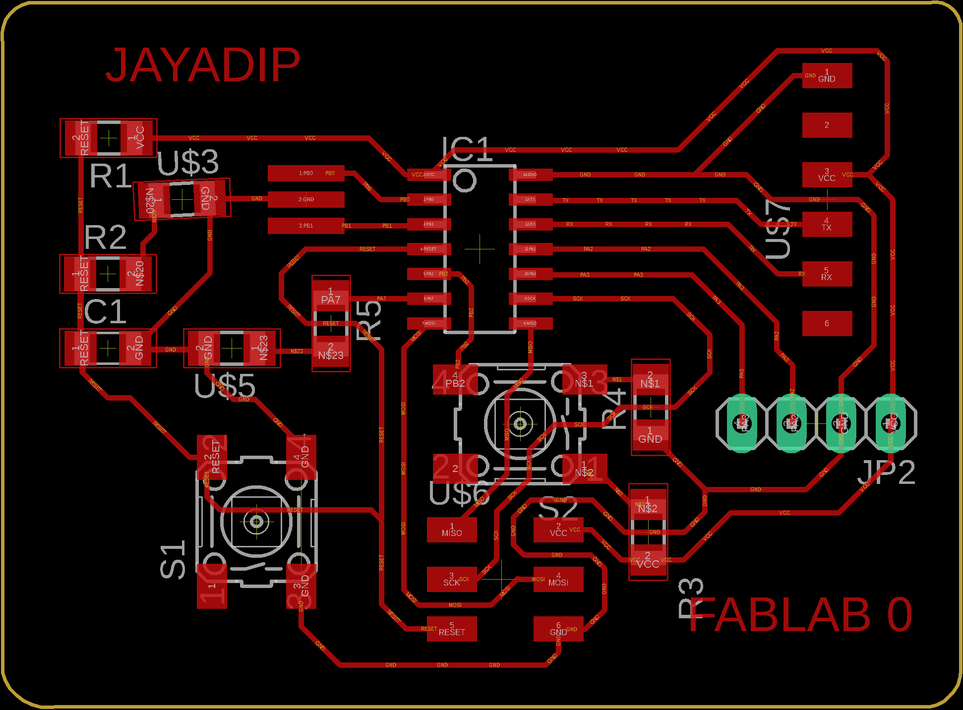
I Choose traces width "6". Completed all routes. I also added some text in my board.
Then, first I export the my board as a color PNG image.
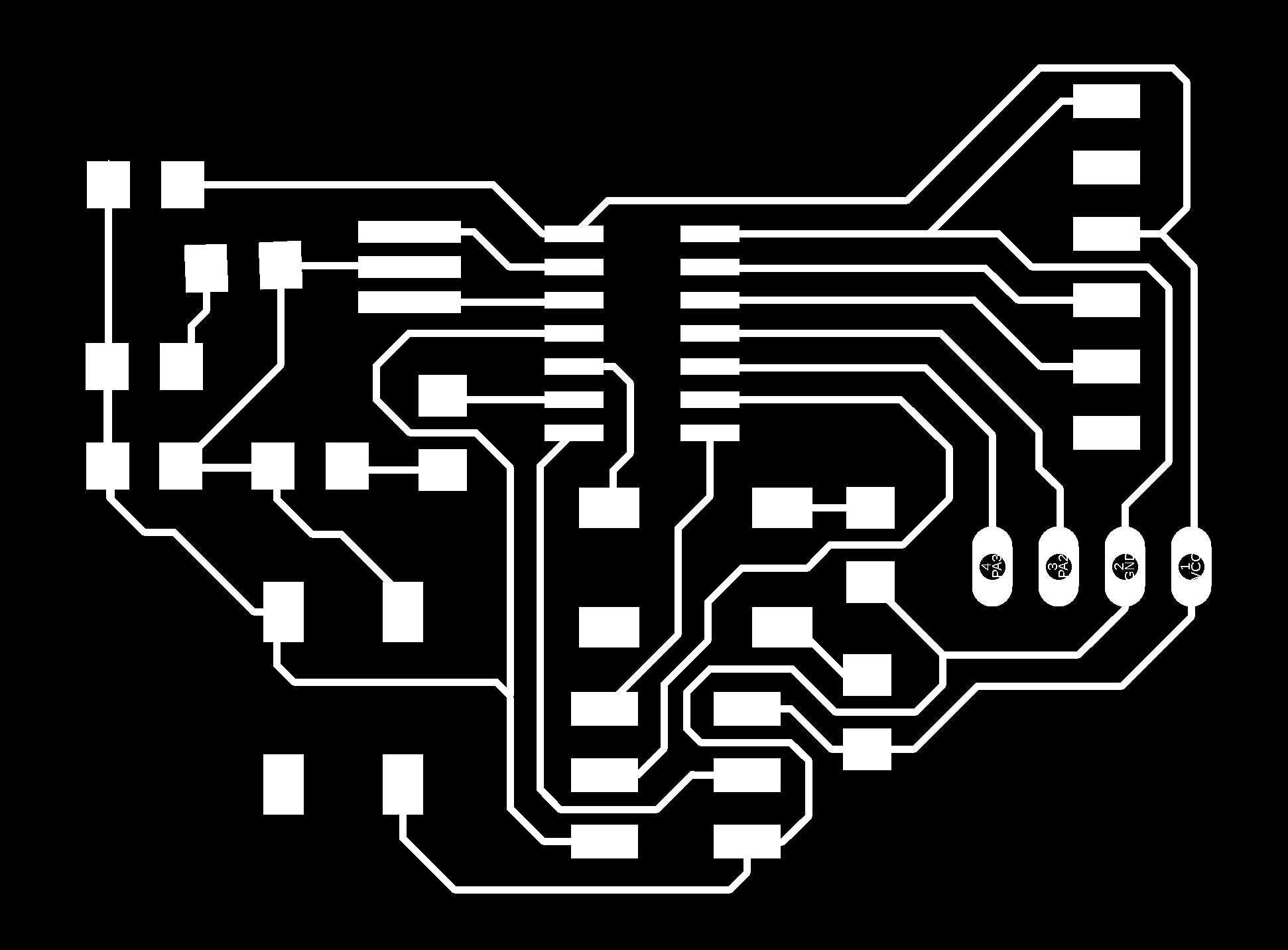
I export the board as a PNG image with 1000 dpi resolution and monochrome image for milling the traces on SRM-20 milling machoine.
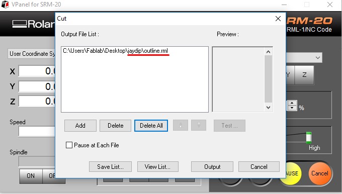
Also export the board outline as a color PNG image for cutting outline after milling traces of board.
milling:
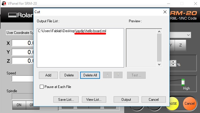
After completing exporting monochrome images, then I make ".rml" unsing 'fab modules'. Next step is milling the board.
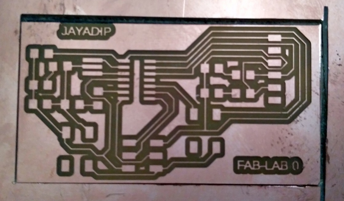
After Milling, my helloworld board looks like below. Now soldering and testing is remaining.
Soldering:
Soldering is a process in which two or more metal items are joined together by melting and then flowing a filler metal into the joint—the filler metal having a relatively low melting point. Soldering is used to form a permanent connection between electronic components.
Testing:
a
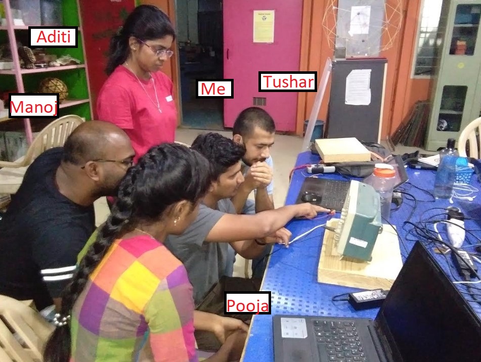
Group Assignment:
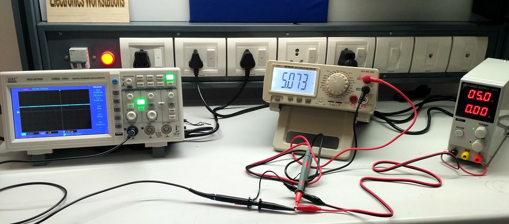
Me and Tushar Kukreja teamed up to observe PCB on oscilloscope and multimeter.
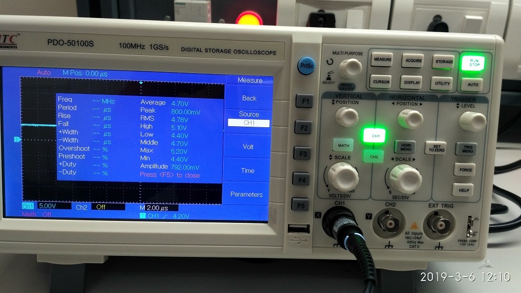
First, we took small trial with DSO(Digital Storage Oscilloscope), DMM(Digital Multimeter) and DC(Direct Current) power supply. We set DC power supply to 5V DC and check voltage on DMM and DSO, As shown in below:
Digital Storage Oscilloscope:
An oscilloscope is commonly used to:
1. Display and analyze the waveform of electronic signals.
2. The digital storage oscilloscope is defined as the oscilloscope which stores and analysis the signal digitally. i.e. In the form of 1 or 0 preferably storing them as analogue signals.
3.The digital oscilloscope takes an input signal, store them and then display it on the screen.
We can see behaviour of any electronic component and also check various parameter using DSO, as shown in below:
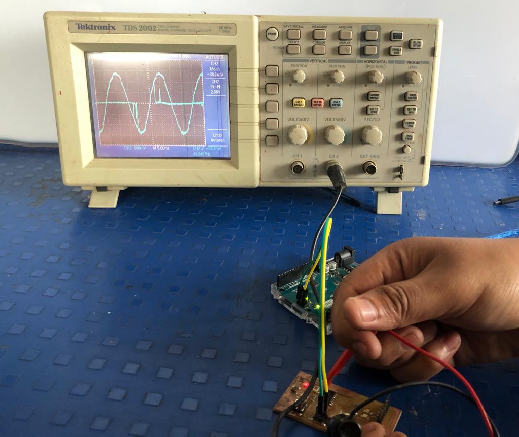
Volatge wavefrom across Oscillator: Observing the volatge wavefrom across on 'helloworld board' oscillator. Good soldering should give rectangular wave, but the board had wavy lines instead. It could be because of some problem in soldering.
Learning Outcomes:
1. Learned PCB design in Eagle software.
2. Explored more knowledge about DSO and circuit testing.