Workflow of assignment
About 3D Printer
3D printing is any of various processes in which material is joined or solidified under computer control to create a three-dimensional object.
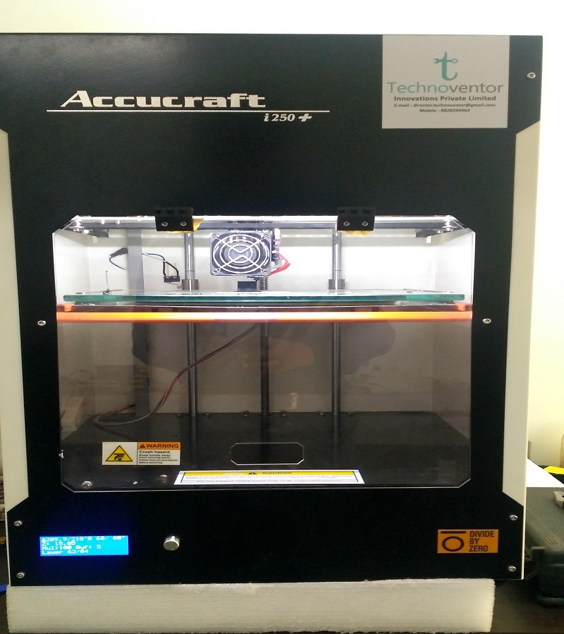
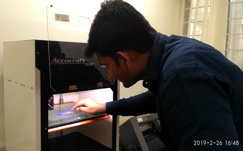
In our fablab have "Accucraft 250i+" 3D Printer. Our printer have Wi-Fi connectivity and easy to operate. Now I am going to my 3D design object to print and make the some test parts for group assignment.
Group Assignment:
To test the design rules for the 3D printer at Vigyan Ashram.
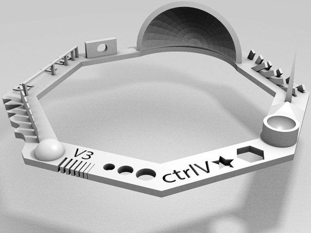
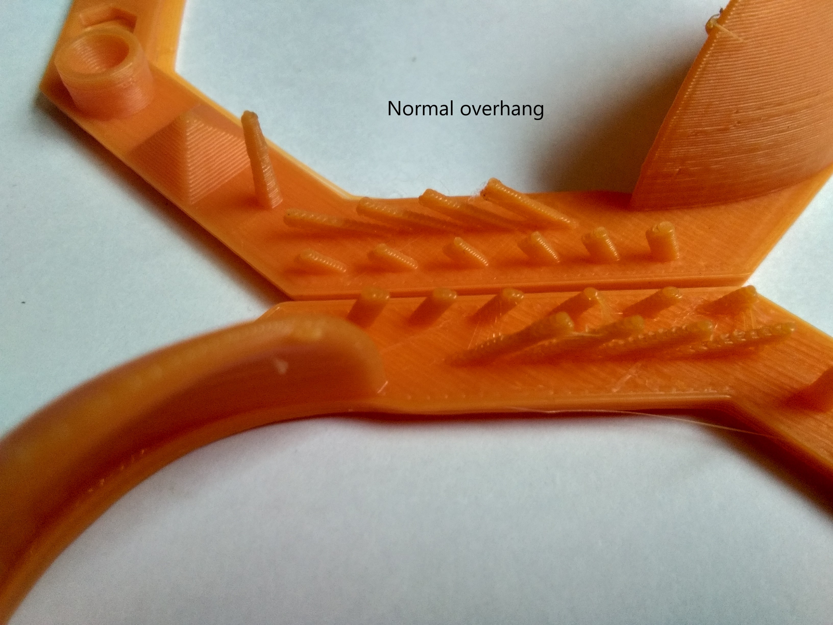
Test 1: For this test we used a Thingiverse file suggested by our instrcutor. The design file looks like-
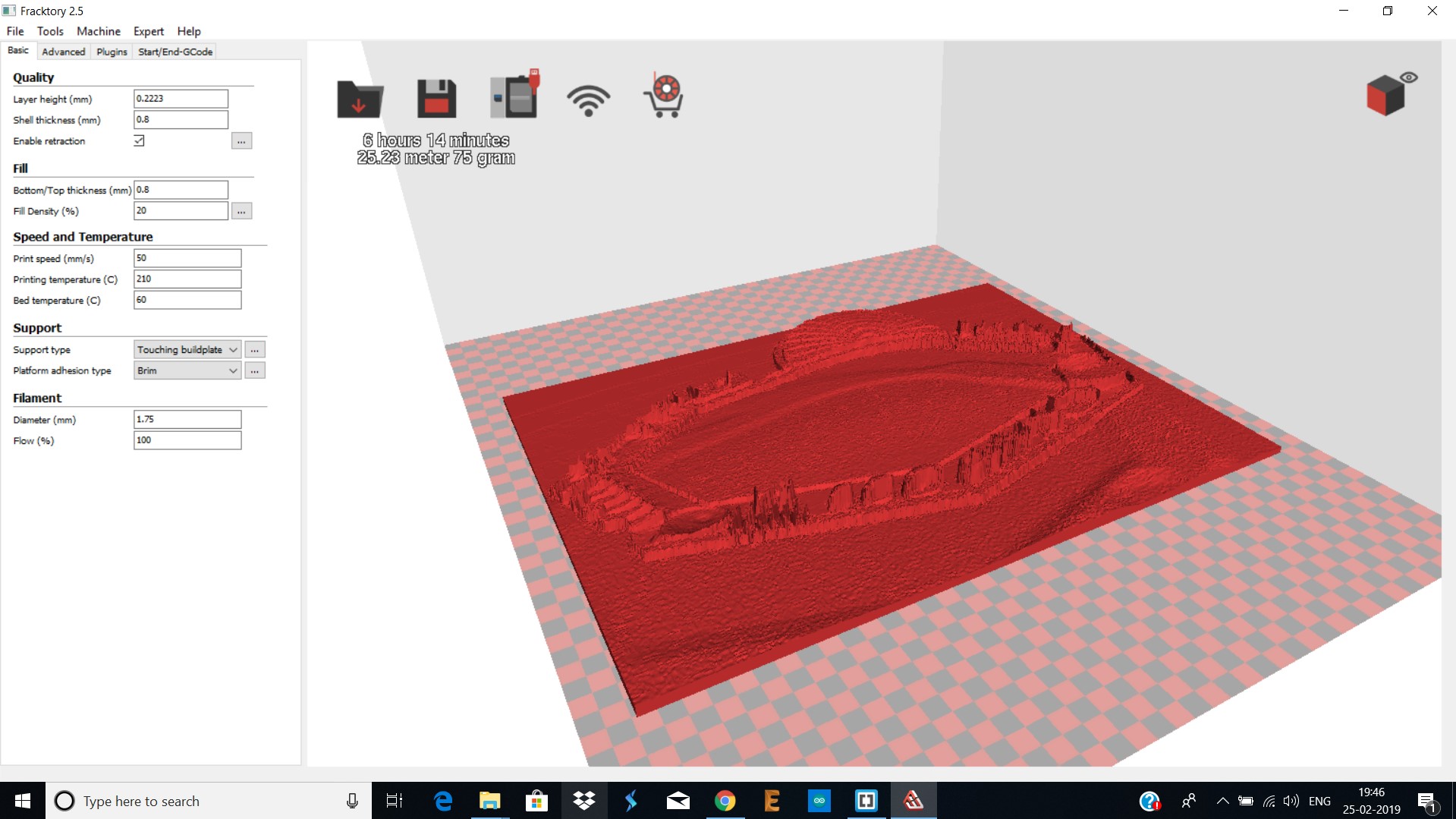
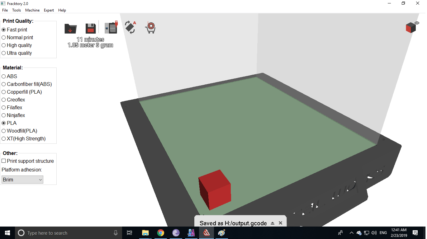
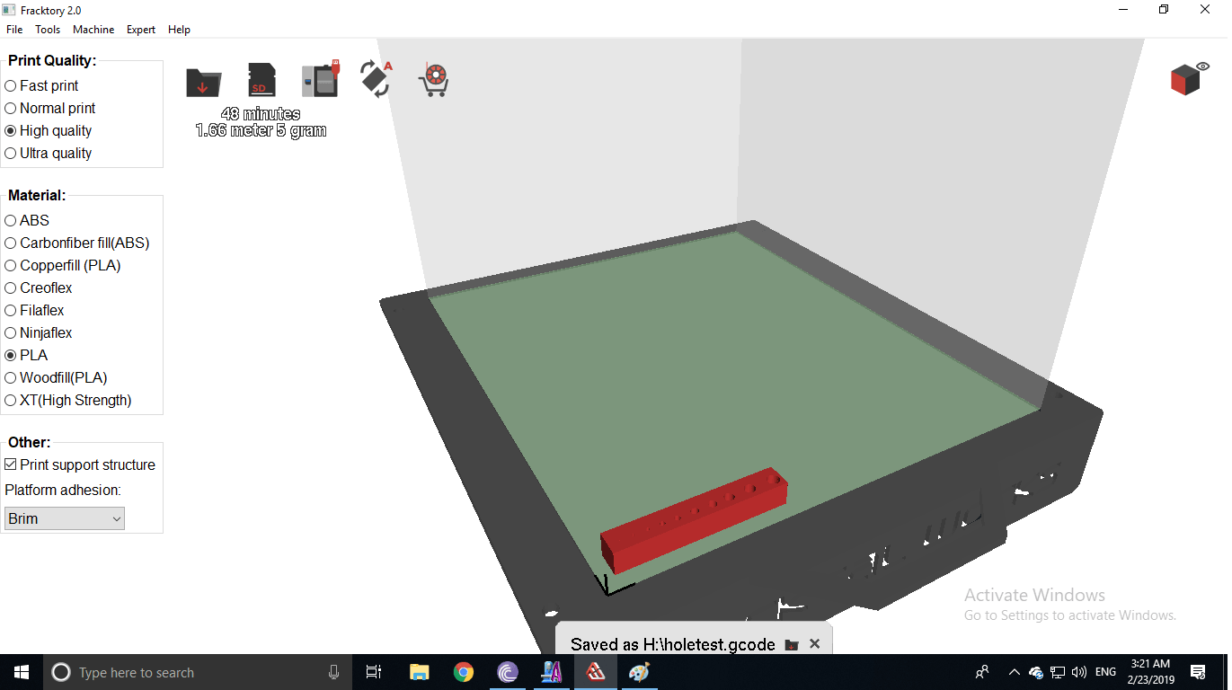
A. Converted '.stl' file to 'G-Code' file:Used Fracktral software, changed setting fill density to 20% and bed temperature to 60 degree Celcius saved the file in GCode.
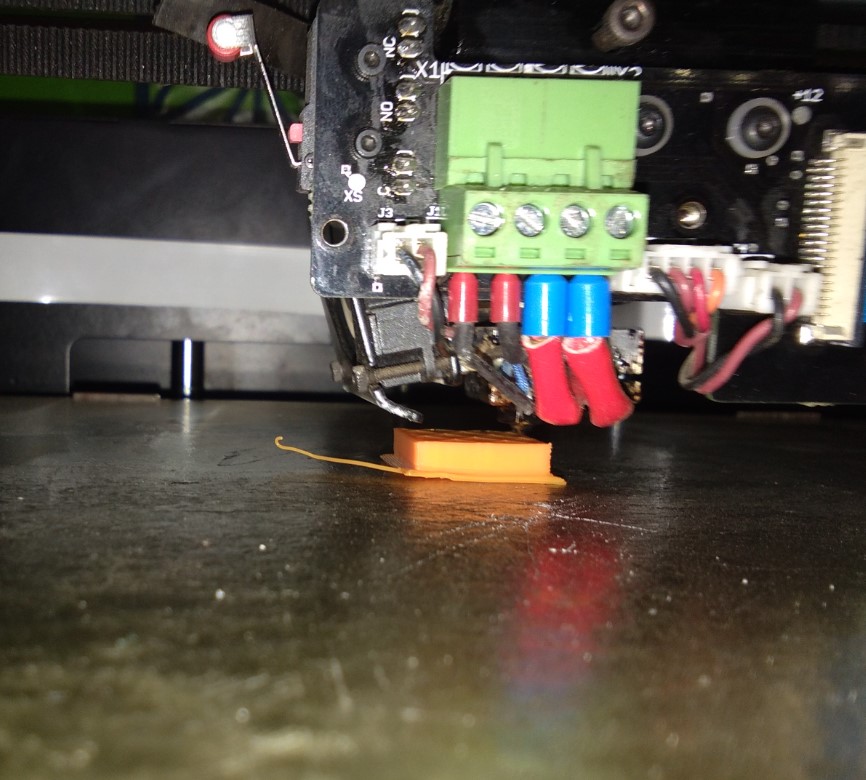
B. Printing: Printed the file on Julia in Normal and Fast print to compare them.
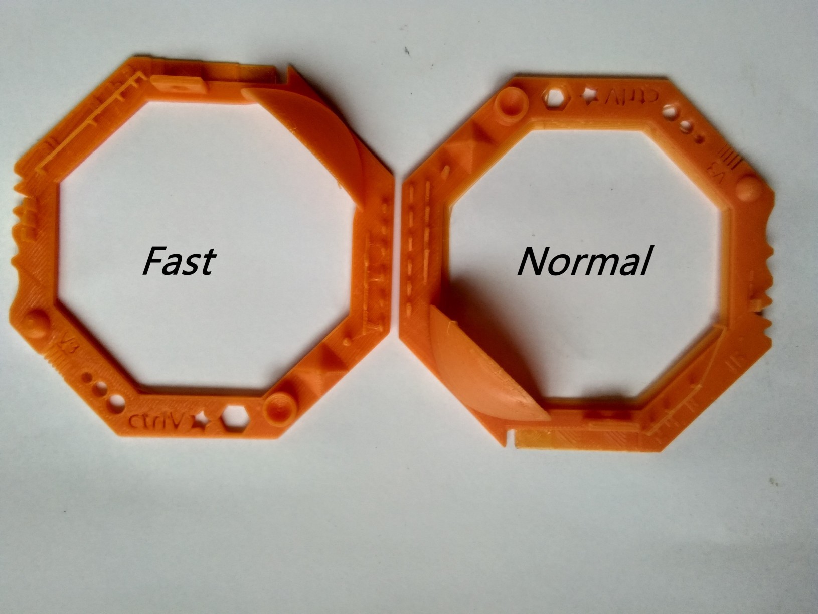
Comparison: we compared the following parameters in the following tests:
a. Z Height
b. Warp Check
c. Spike
d. Hole in wall
e. Raft Test
f. Overhang test
The conclusion was that there was no major differnce between print quality except for Overhand test. Normal print had better overhang results compared to normal print. It is visble in the picture below:
Test 2-In fill Test: In this test we made 4 cubes in fast, normal, high and ultra print to study and compare there appearance and sizes.
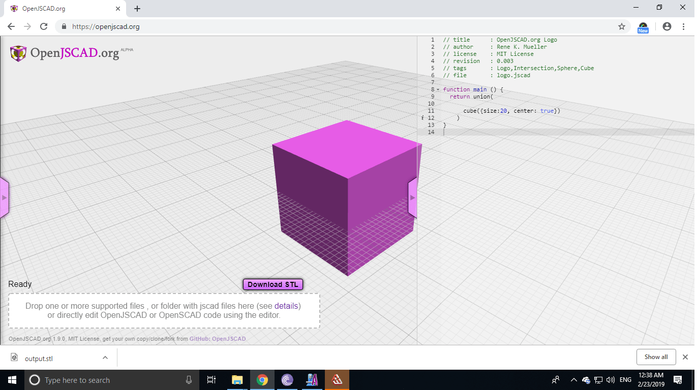
a. Design: We designed cubes of size 20mm in OpenSCAD.
b. Print: Converted file to 'G-Code' and printed it on Julia. The shapes were small so it didn't take very long to print them.
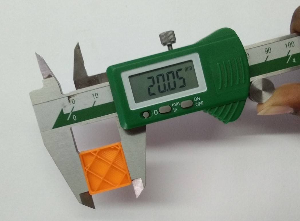
c. Results: The differnce is explicitly visible from fast to ultra print. The ultra print has squares small, precise and closer compared to high, normal and fast print.
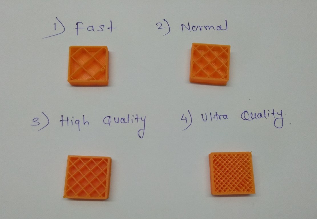
d. Comparison: The length of ultra print was 19.90mm and fast print was 20.05mm. I thnk depending on the application the choice of print should be made.
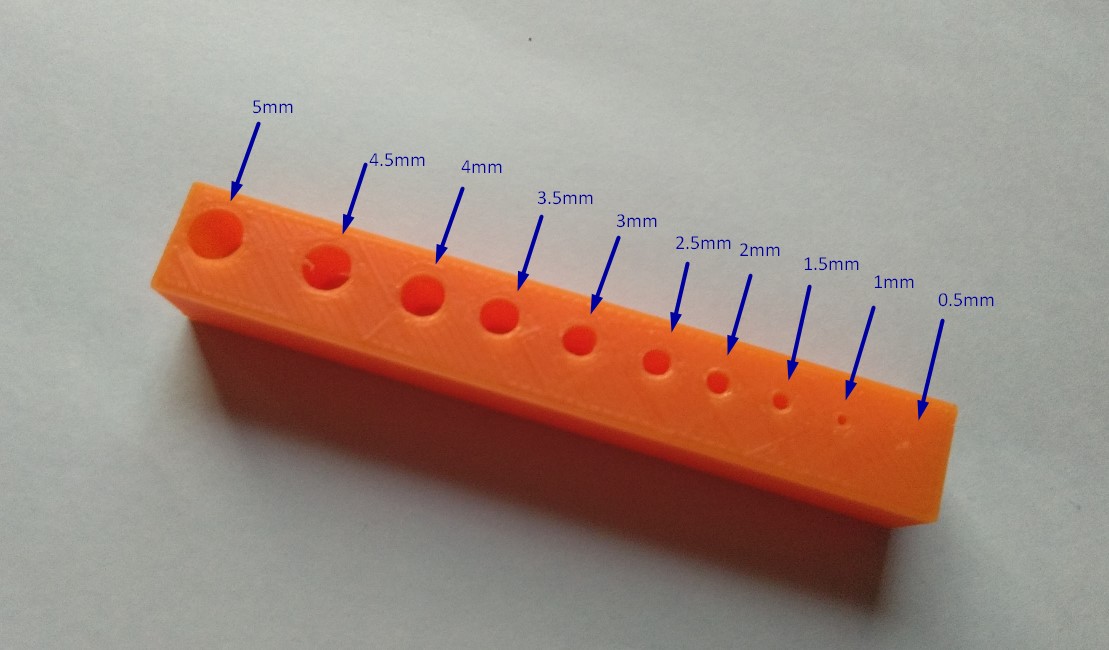
Test 3:Hole Test Made holes from 0.5mm to 5mm diameter and printed them in a cuboid.
Test 4: Resolution Test: Lines of 0.5mm to 5mm thickness were printed. Clearly, the thinnest line wasn't printed well.
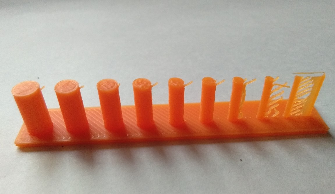
Conclusion: For our 3D printer Julia at Vigyan Ashram, I concluded to keep a minimum thickness of 1mm. And depending on the design and application I will choose between fast,normal,high and ultra print. Because although Ultra print may aesthetically look the best but it takes longer time to print. At the same hand, if my design involves overhang, I will not prefer fast print.
Individual Assignment:
Before Fab academy I was did a project in vigyan ashram named 'Digital Hygrometer'. In that project I used dry-bulb and wet-bulb thermameter. there were I needed a mount for the Dry-bulb and Wet-bulb temperature. So I am going design the same in this 3D design week.
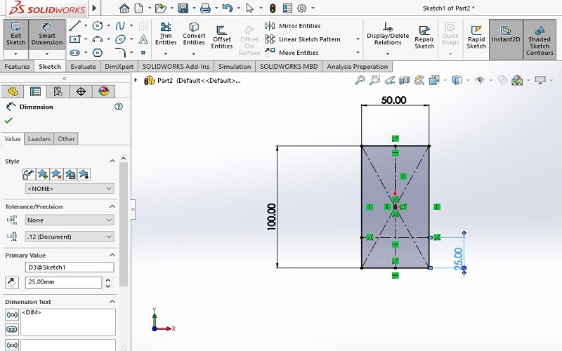
I took the 100mmX50mm dimensions for the object.
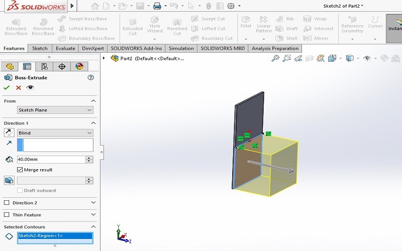
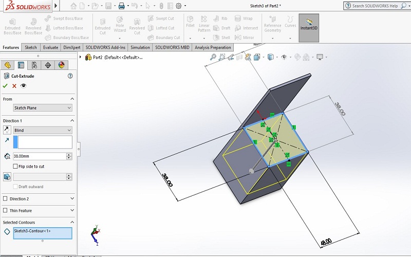
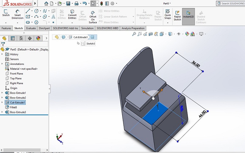
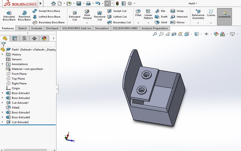
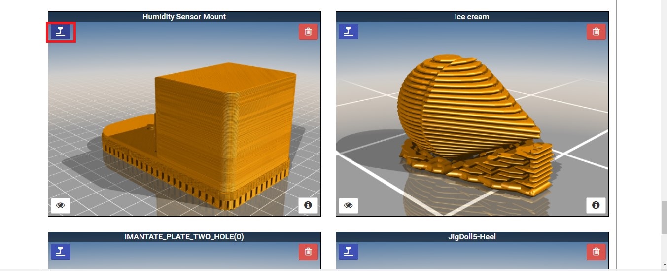
Now, design part is completed. This is the my 3D mount for the temperature sensors(Dry-bulb and Wet-bulb). I will be use this 3D object in my 'Digital Hygrometer' project.
Making G-code:
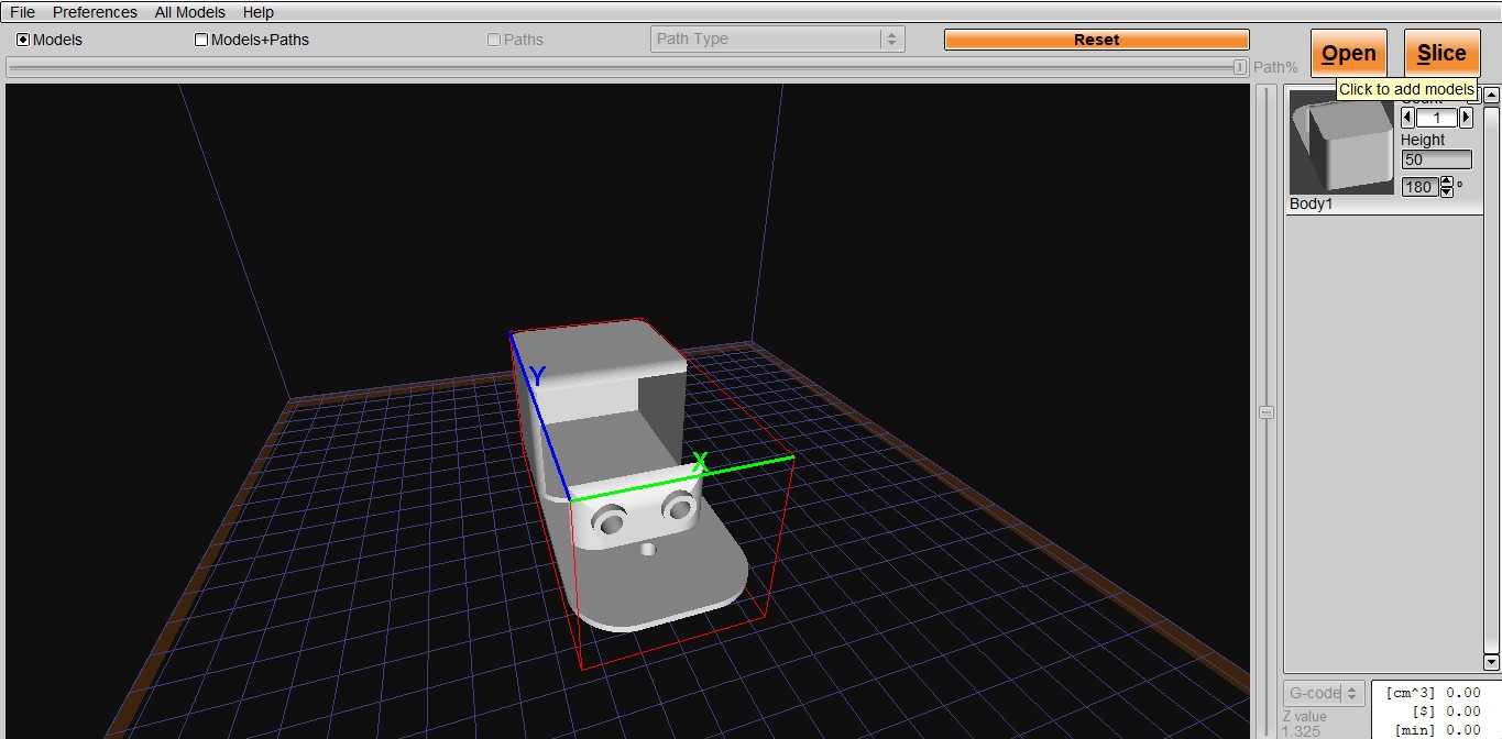
Now its time to make "G-CODE". For this I used KISSLICER software. In this software I open my STL file.
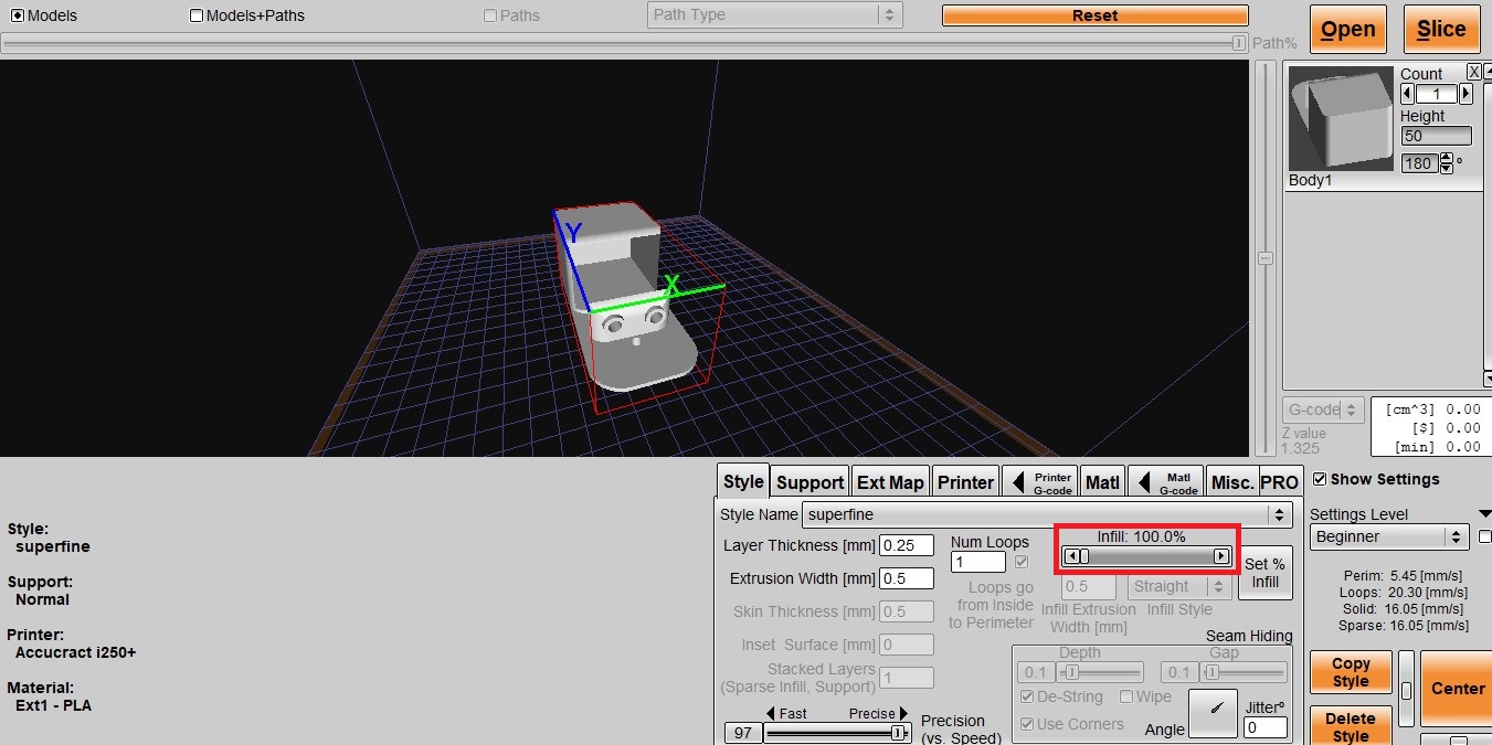
Then, I open the setting option in this I choose superfine style. Infill is a very important factor to a print's strength, structure, and weight. I choose it as 100%.
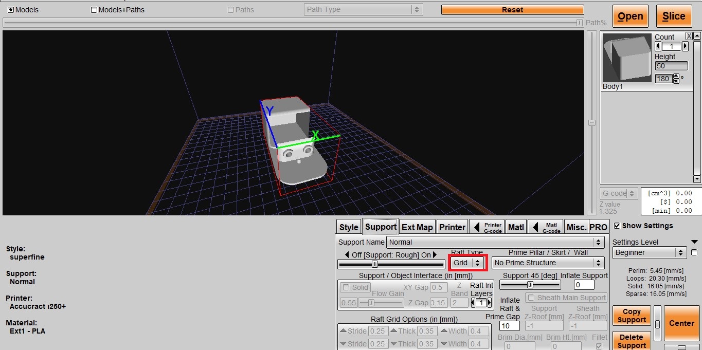
Then, I selected the support option , depending on the specific 3D Printing technology and the complexity of the 3D model, this can mean that a 3D print requires support structures. I choose grid support structure.
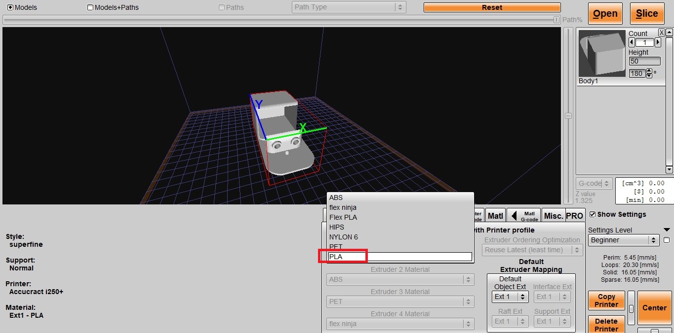
Now, next setting is very important it is about material selection there are multiple option for material, but it is must that to select correct material. I used PLA material for printing.
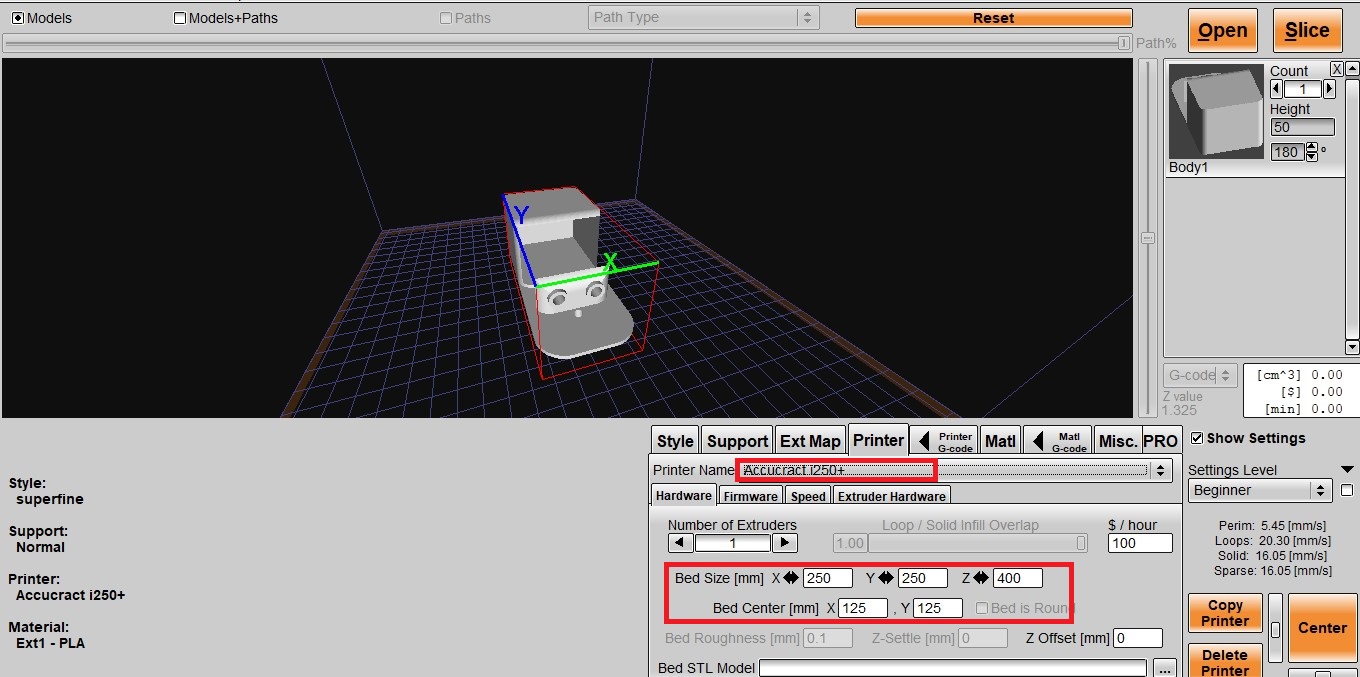
Now its time to choose 3d printer we have Accucraft 3D printer which is having bed size 250*250*400mm.
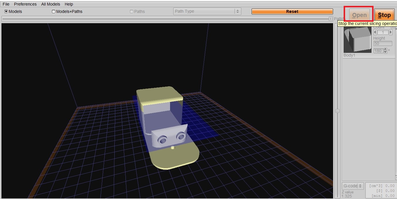
Then, I choose the slice option to make G-CODE. Now my G-CODE is ready to print.
Printing:
I coated the bed with the mixture of acitone thermocol for to stick the object to the bed during printing.
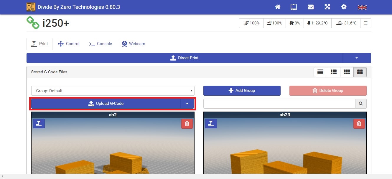
Now, I am uploading G-code to 3D printer. Our 3D printer user interface on web using WiFi.
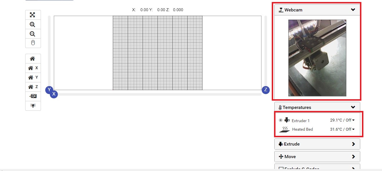
WEBCAM: We can see here how 3D printing is going on.
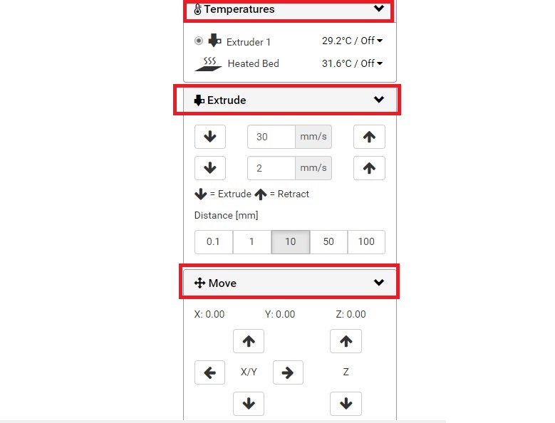
1. Temperatue: We can set bed and extruder temperature here. Also On/Off temperature control available here.
2. Extrude: We can extrude the material using this option with various thickness and 'ON' time of extruder.
3. Move: Using this option, we can move the bed X,Y and Z axis.
After clicking this, 3D printer started printing my object.
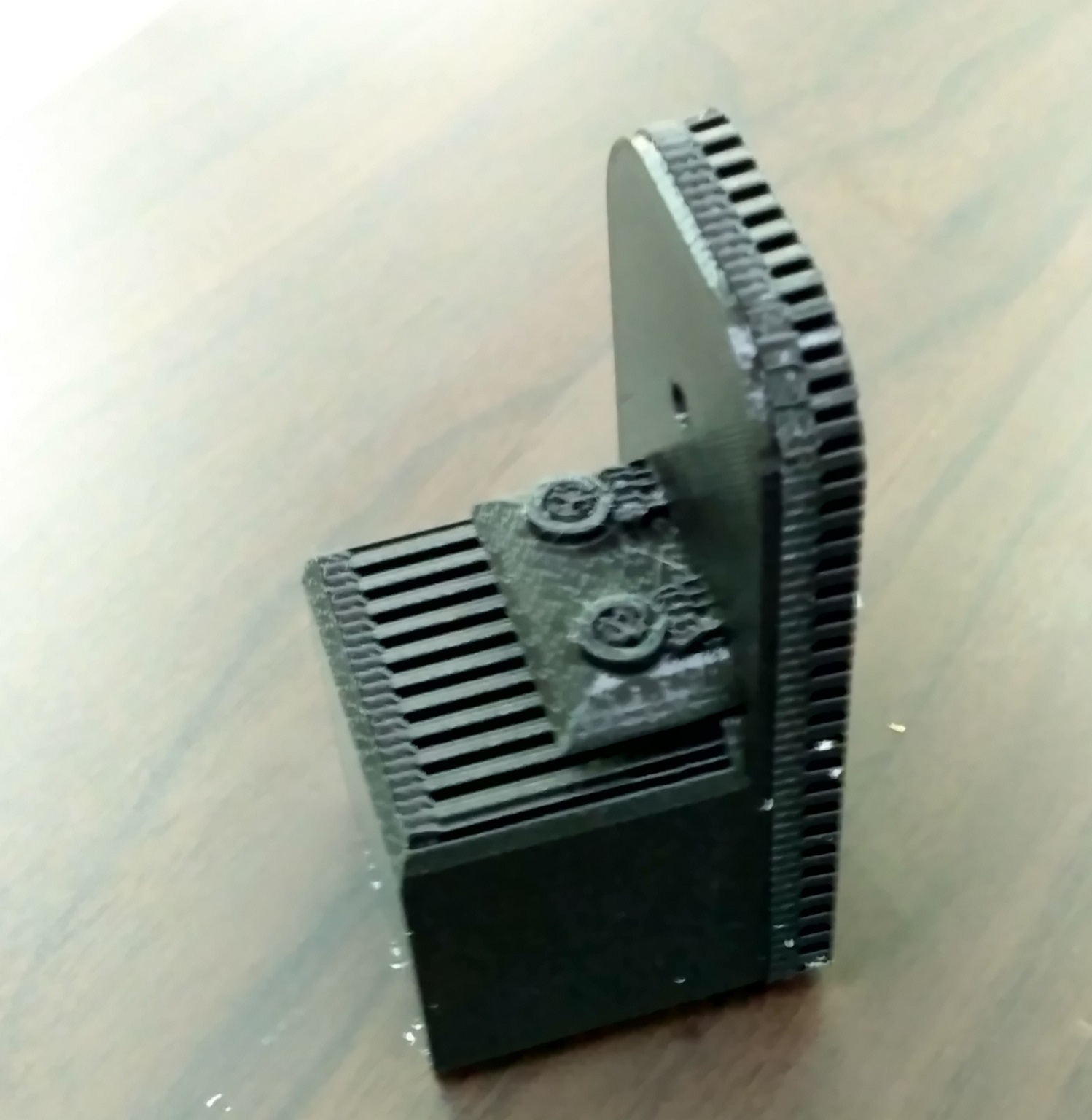
Successfully printed my object and still remaining work of removing supports.
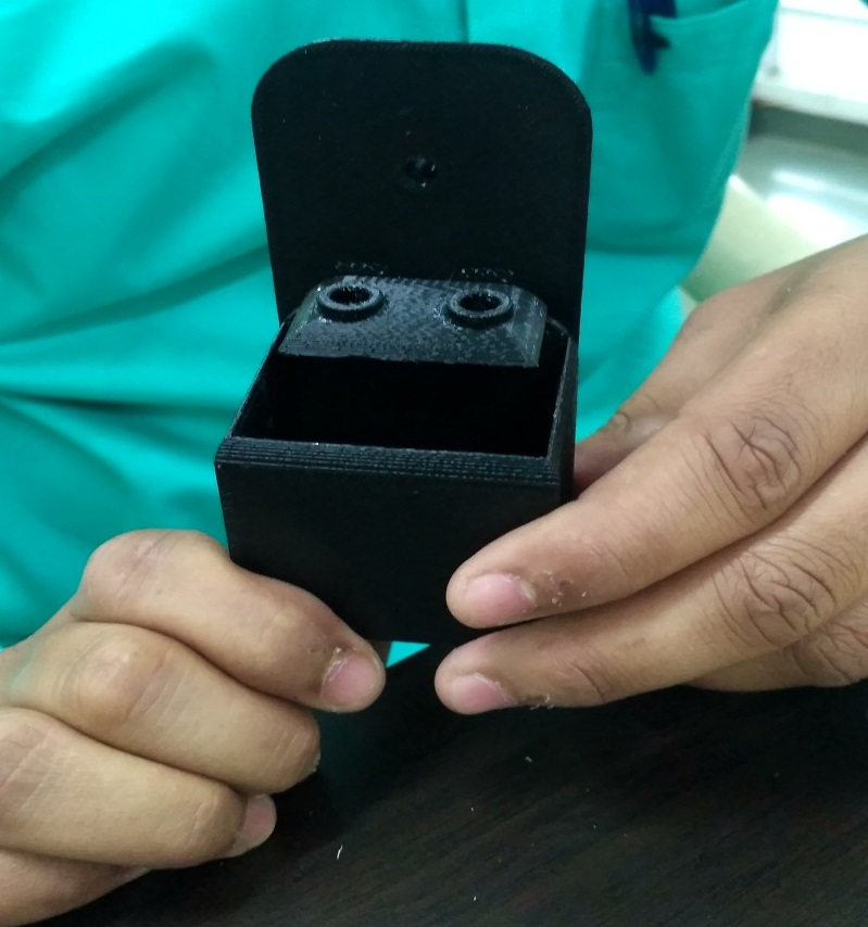
This is the final shot of 3D printed object, after removing supports.
3D Scanning:
3D scanning is the process of analyzing a real-world object or environment to collect data on its shape and possibly its appearance. The collected data can then be used to construct digital 3D models. A 3D scanner can be based on many different technologies, each with its own limitations, advantages and costs.
3D Sense:
The Sense is a handheld, short range 3D Scanner with full HD color that captures and processes data in real time, generating a complete polygon mesh. speeding up the data acquisition process by over 60%.
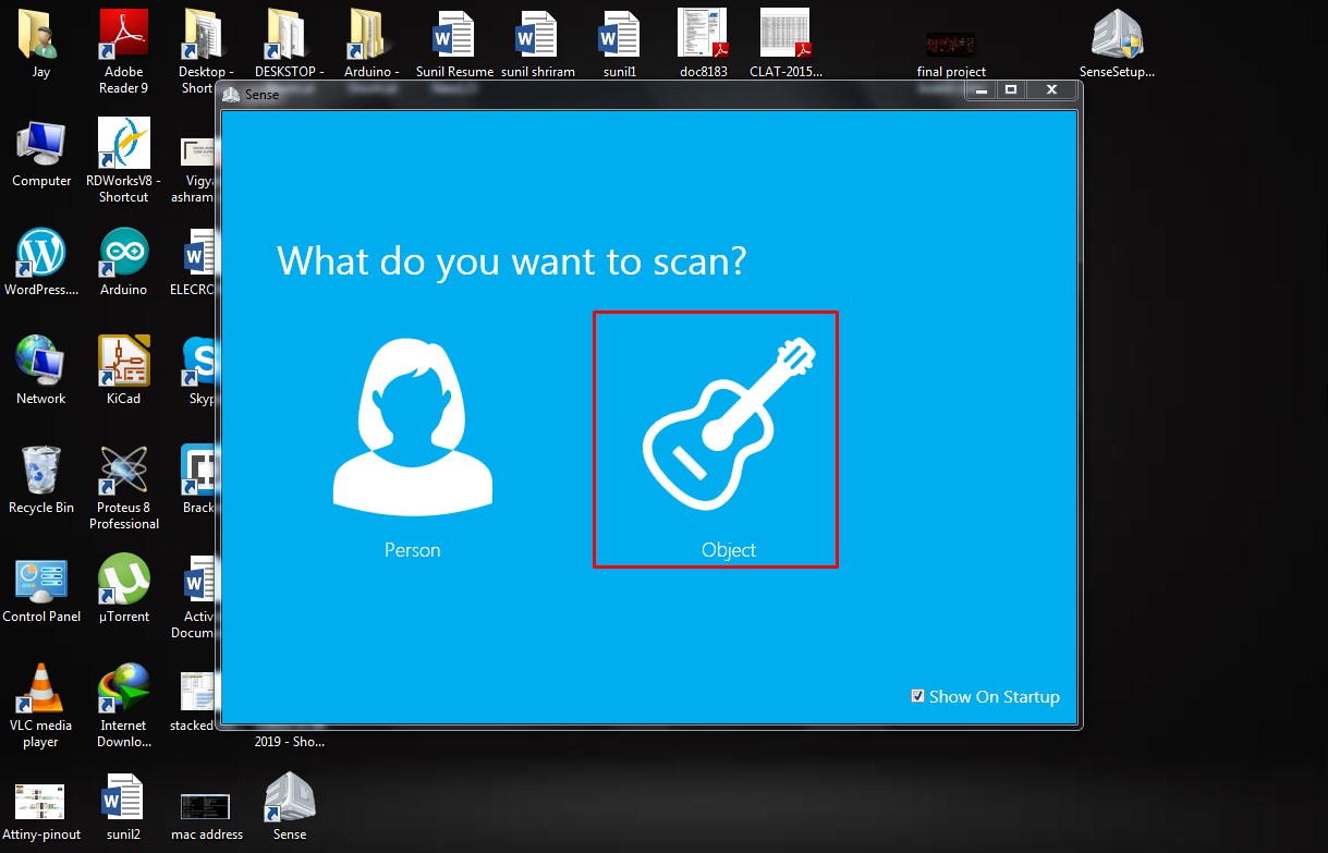
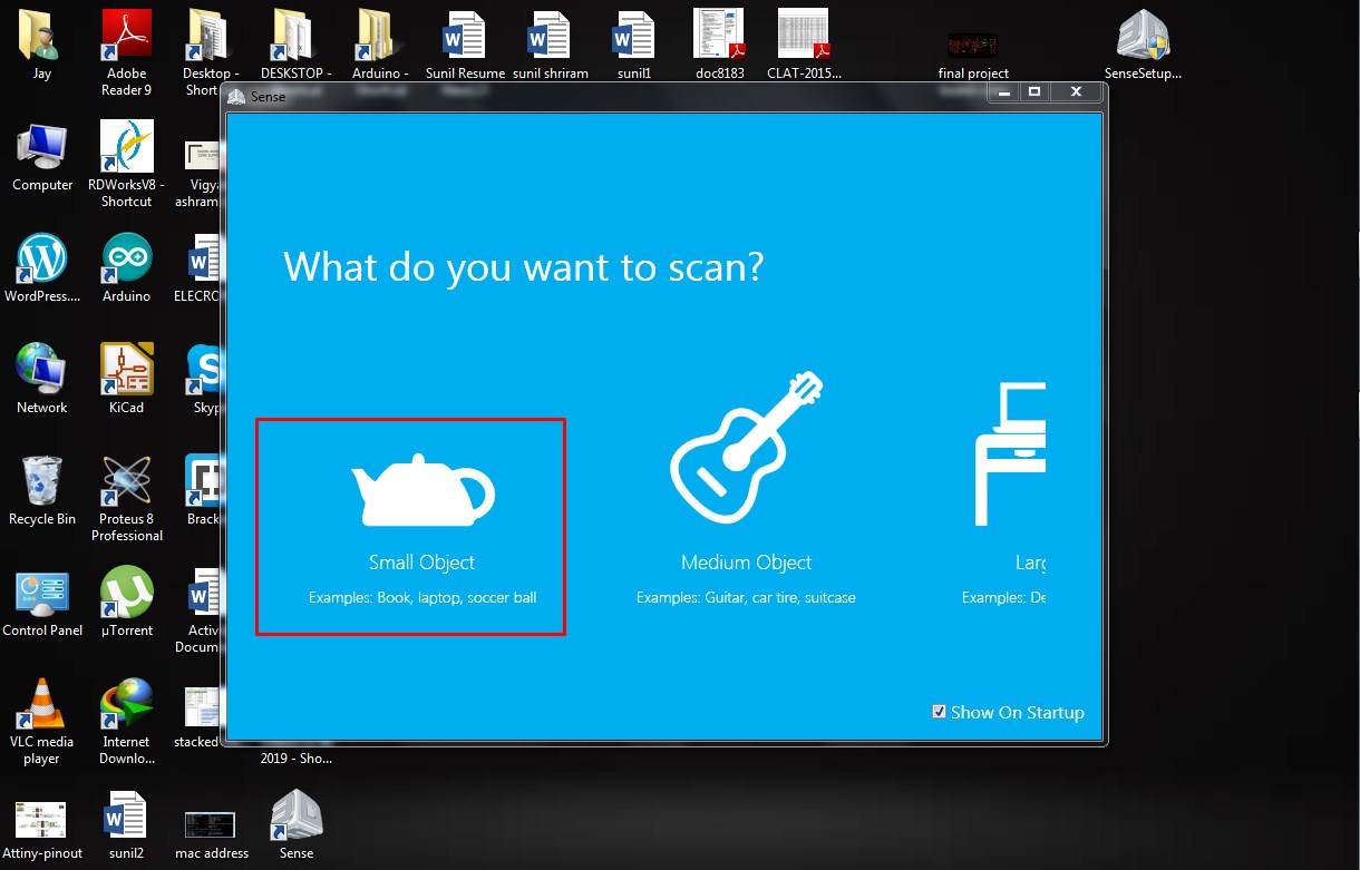
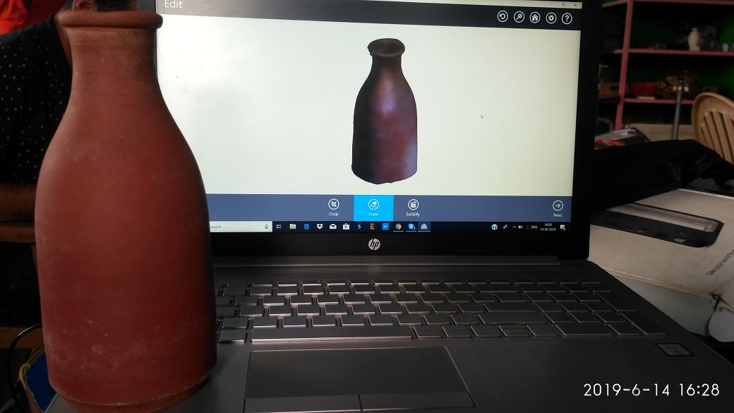
I'm going to scan my mud-water bottle using 3d Systems Sense. The UI is simple and easy to use. A few quick tips the object needs to be rotated on the single axis . Any tilt in the axis will result in distortion of the model which is generated .
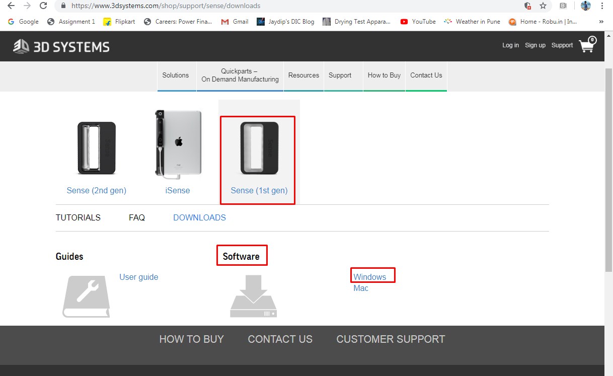
Downloading 3D sense(1st gen) from 3D systems for windows.
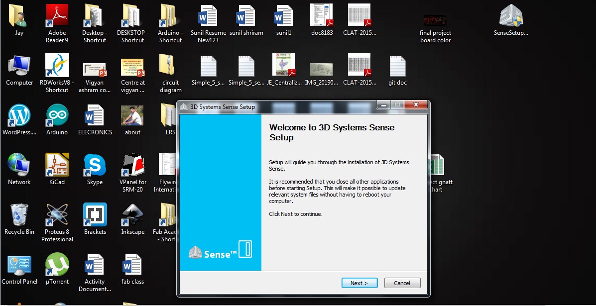
Installing 3D sense(1st gen) in my computer.
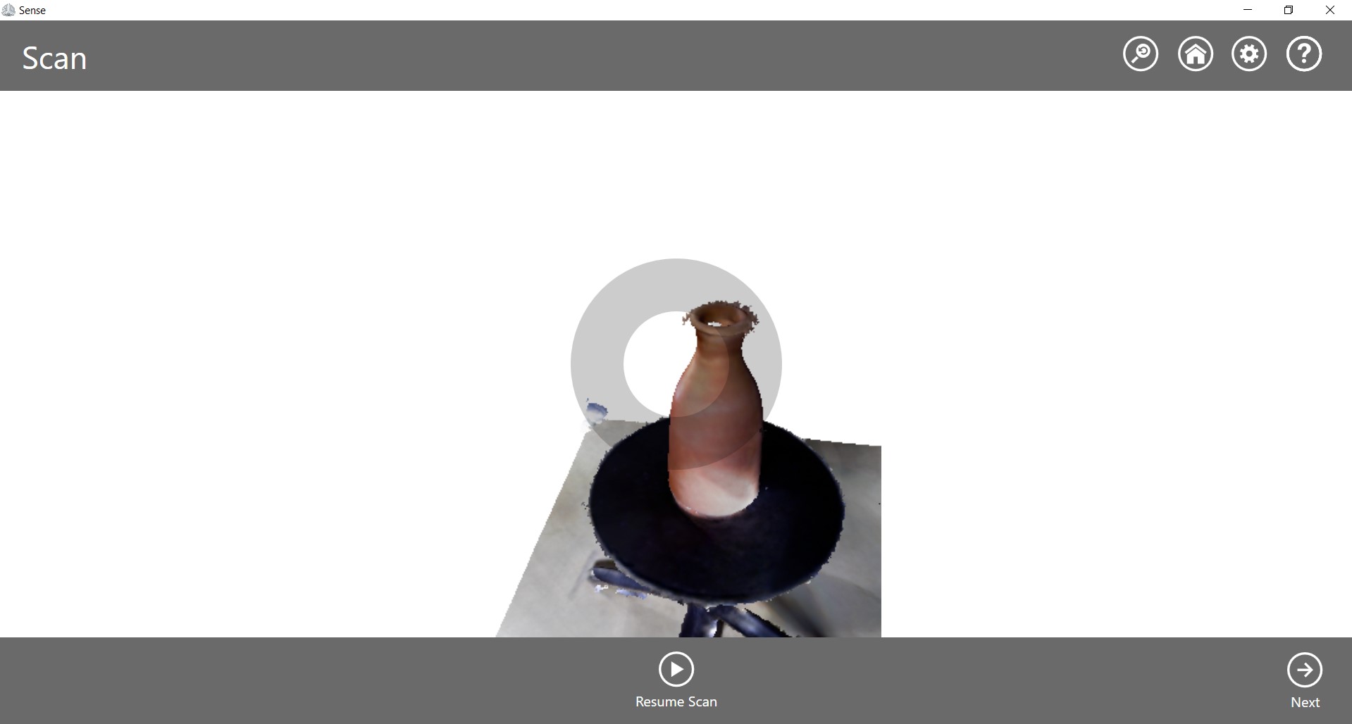
After scanning, I had to edit the scanned object file.
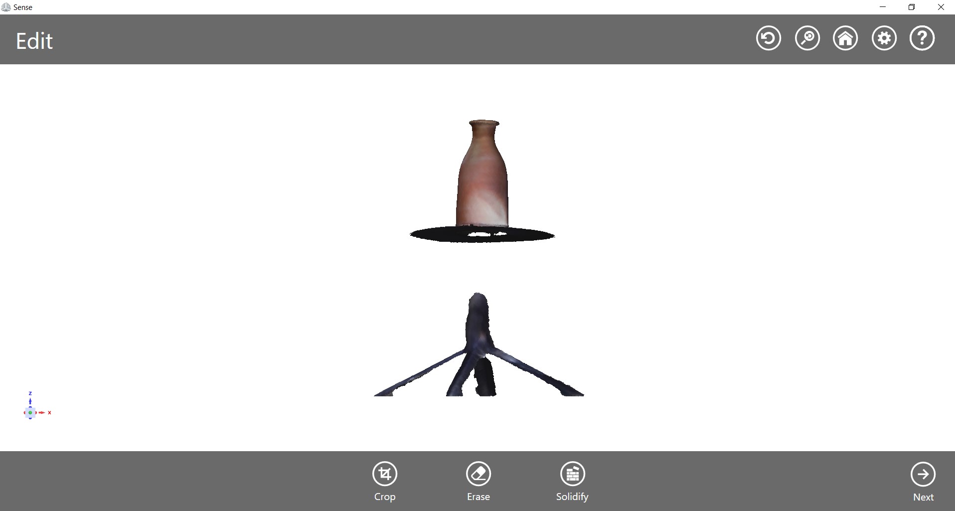
There are some options after scanning. i.e. Crop, Erase and Solidify. Using these features I get following object.
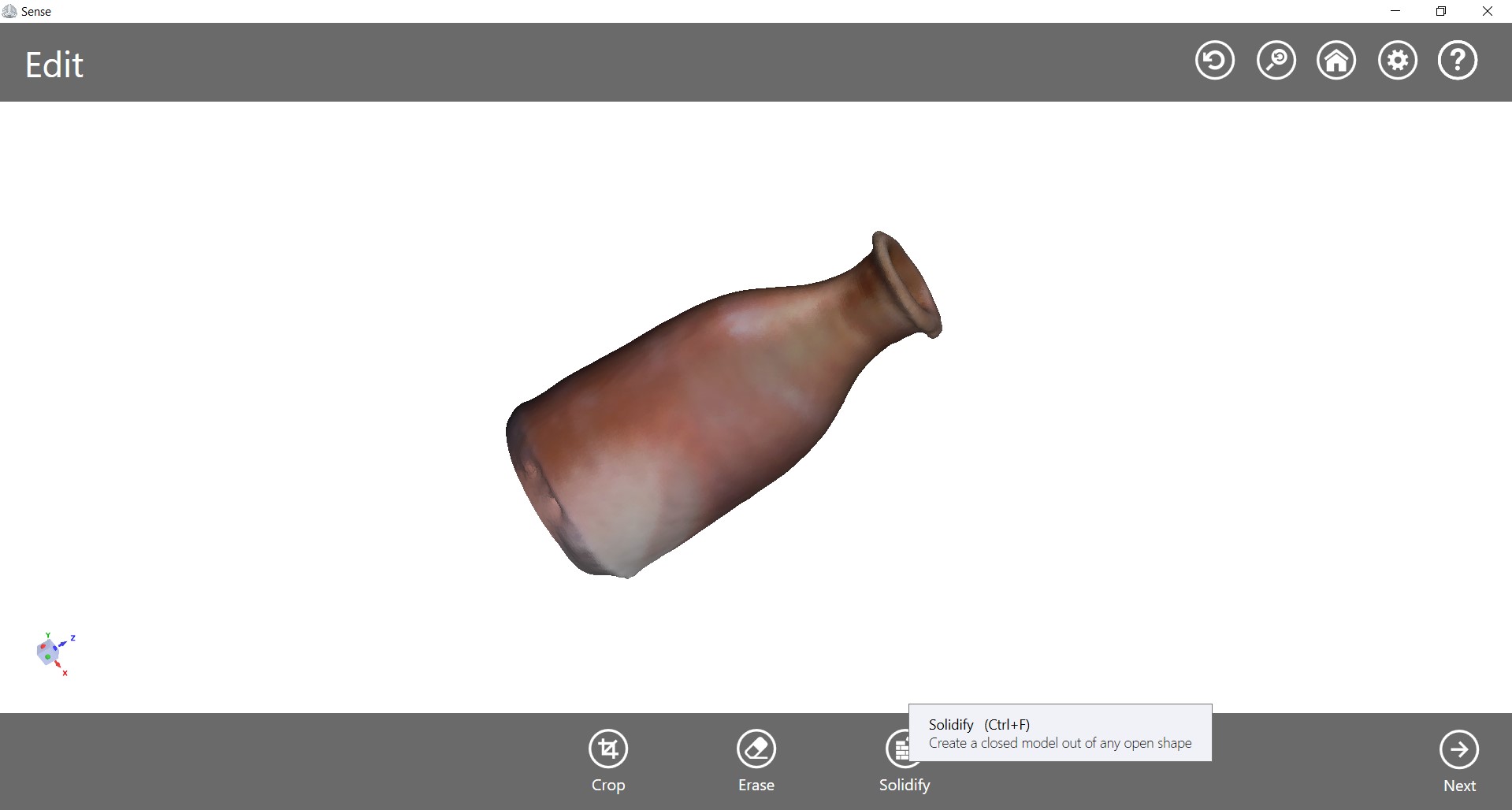
Now, it need to be final touch-up.
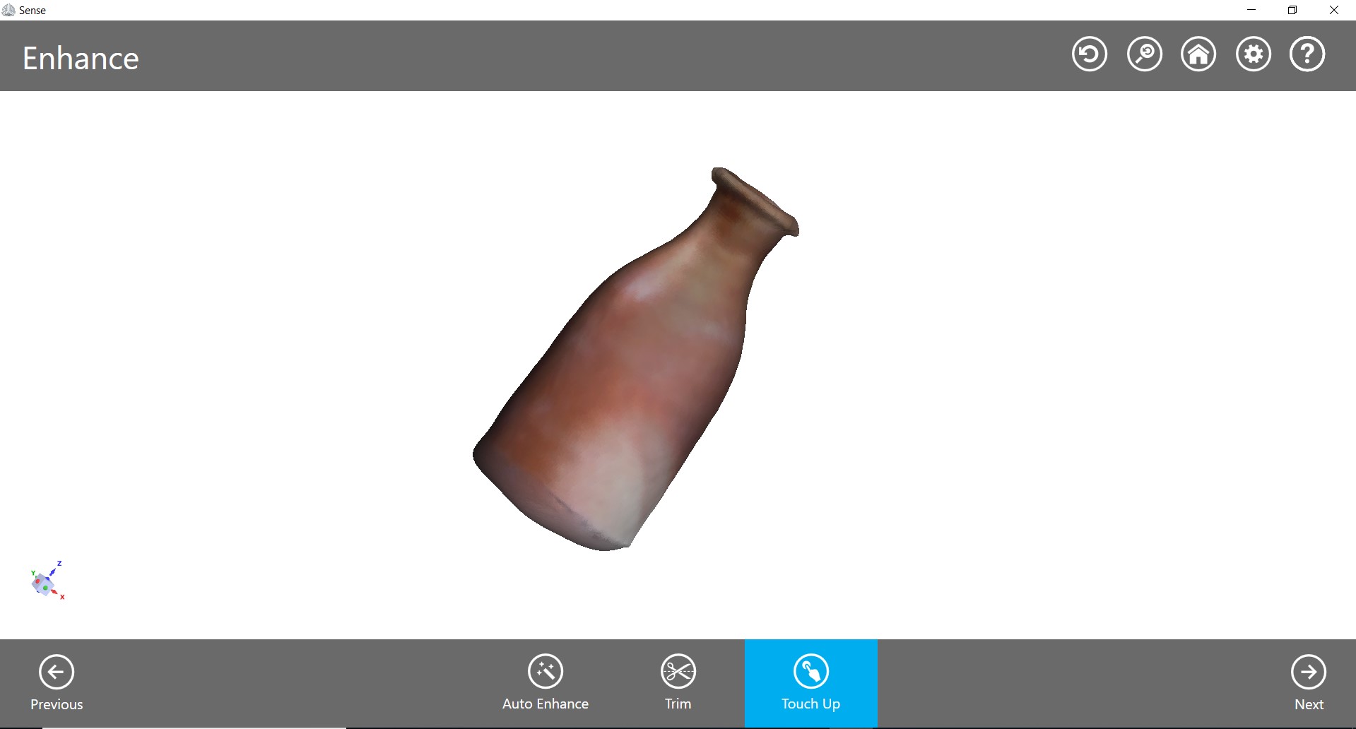
What could be improved:
The mud-water bottle, I scanned is done quite well. Overall the shape and colour of the vase is perfect.
Yet I feel the scanning can be improved in the right environment of light. A room with optimum light, object fixed at a place and 3D scanner moved steadily will improve the scanning details.
Learning Outcomes:
1. Learned 3D design aspects and understood 3D printing concept.
2. I also did 3D scanning.