
Workflow of Assignment:
Highlights of the week:
The group page has the entire content of Mechanical and Machine design.
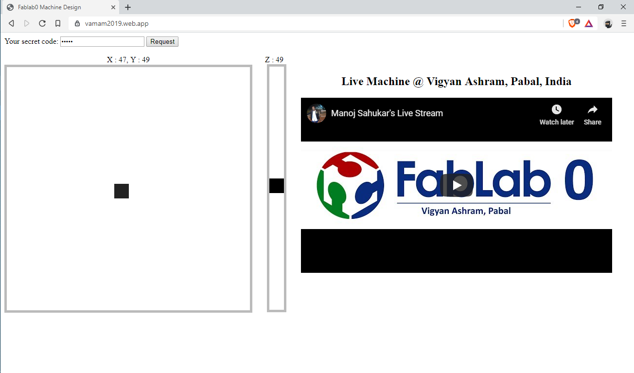
Link to control interface: https://vamam2019.web.app/
Cablebot Description:
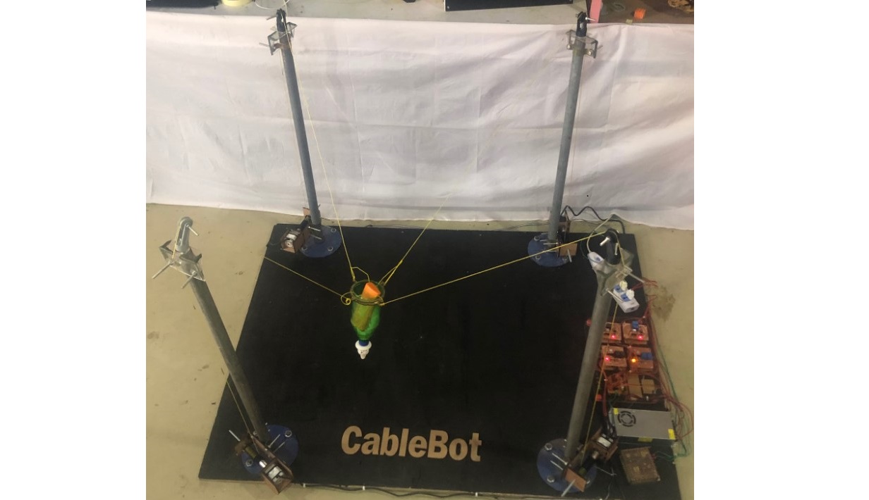
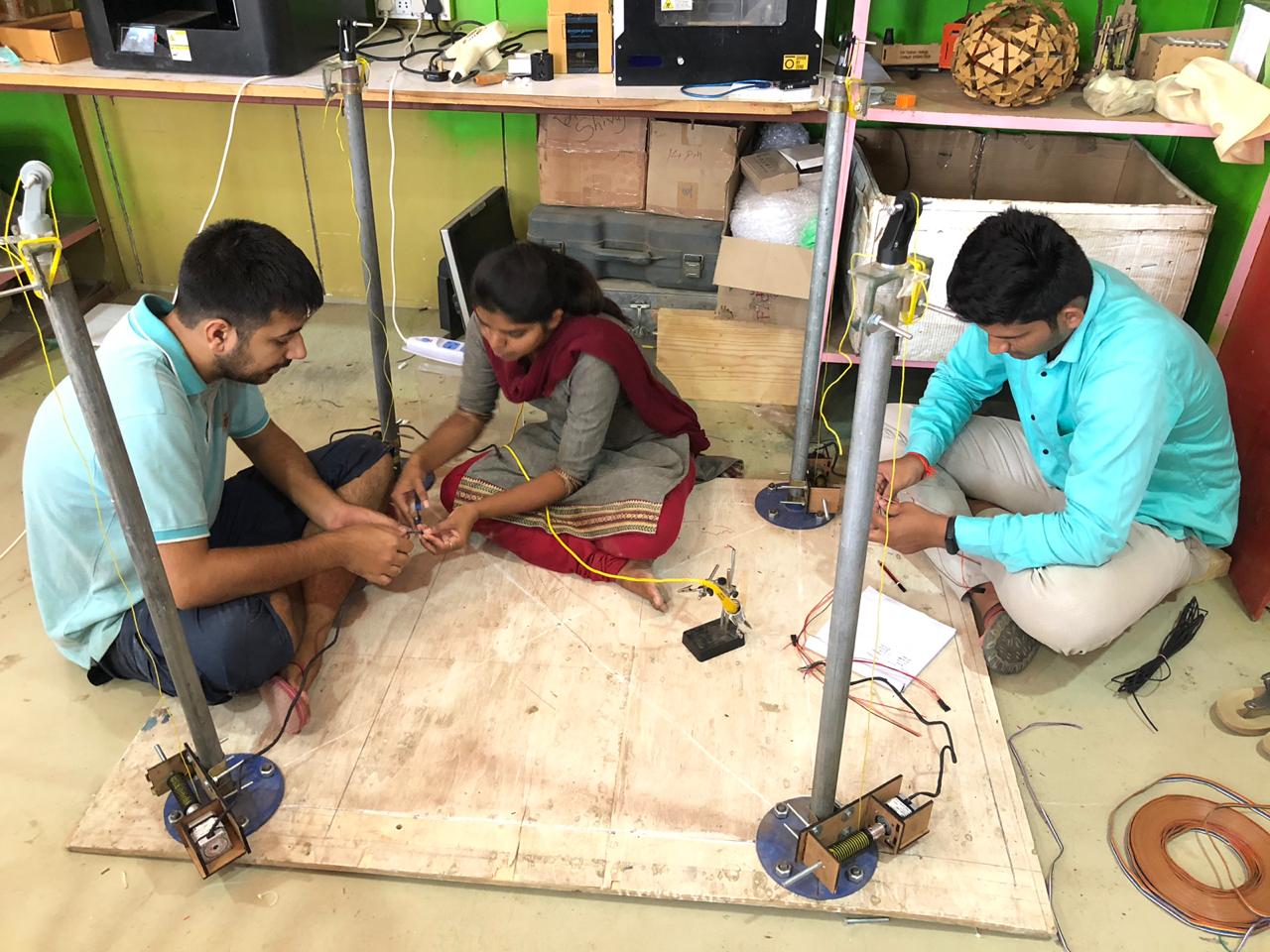
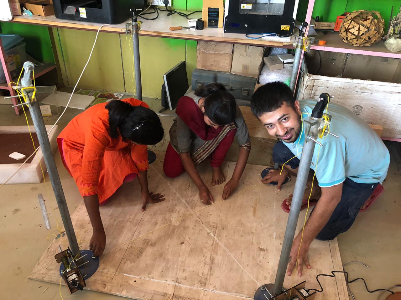
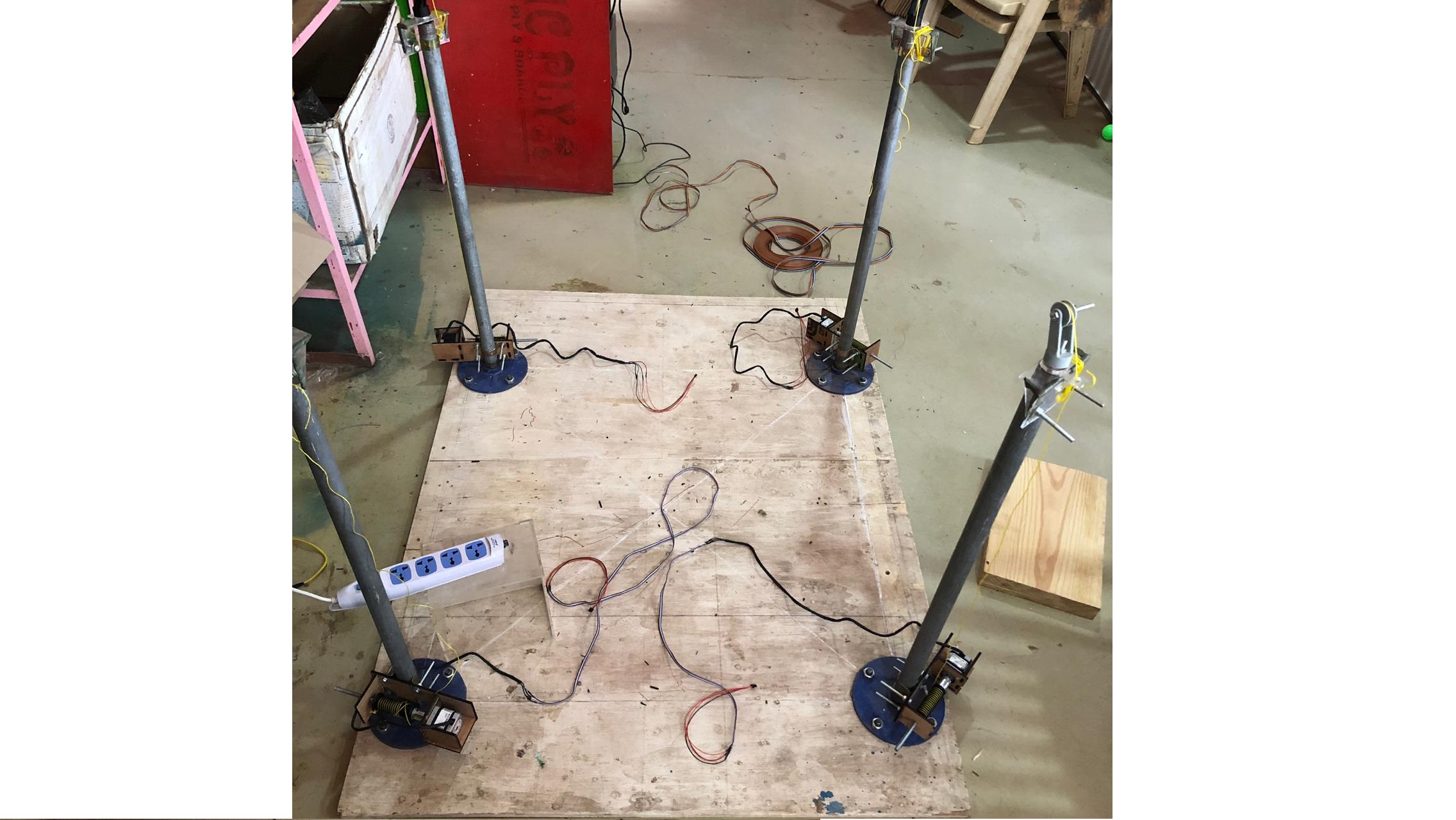
Cablebot has been made with the vision to solve the challenges of farmers with large farms. Sowing seeds, watering and other activities on large field are challenging. Our model is the first step towards automation in farming using "Skycam" principle.
Cablebot Working:
We have used 4 cables to move the end effector. For every cable there is a stepper motor, winch and motor controllers in serial bus to achieve the motion.
Individual Contribution :
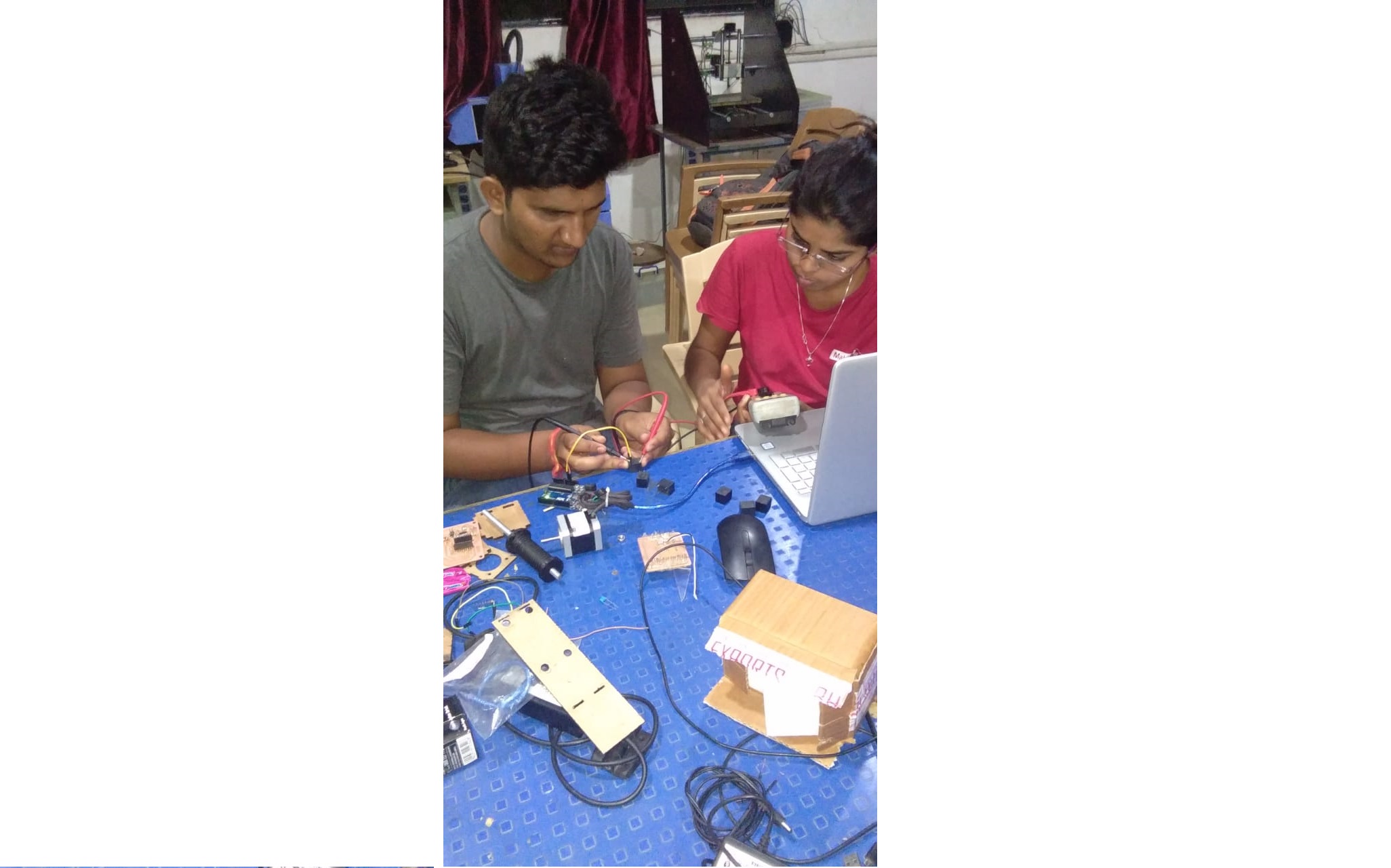
For this assignment we all 8 members from vigyan Ashram will work togethet as one team, Manoj Sahukar leading the team ,he divided all in 2 team of four people as Control System and End effector team, For control System Me and Aditi Kharade we are working whole electronic part.
We are going to use Master-slave type of communication for controlling whole system.We are using Arduino -uno as our master board and we made slave boards by own. We decided to divide the slave part in 4 design.
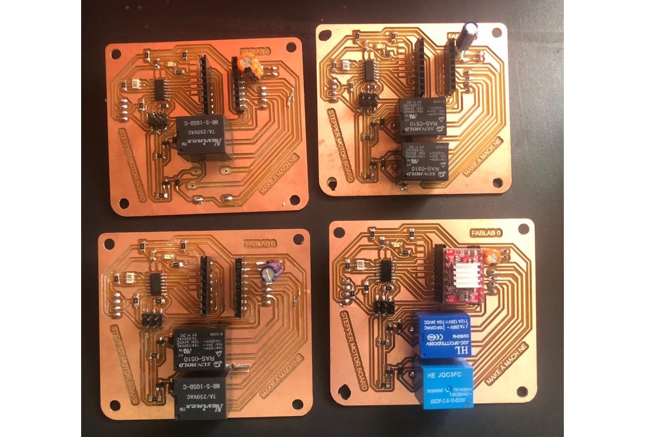
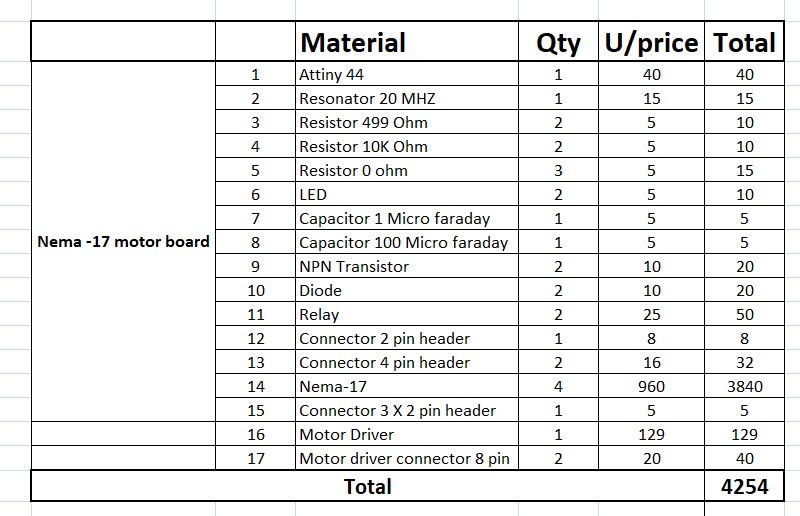
1.Design for Nema-17 motor board -4 nos.(for 4 pole each)
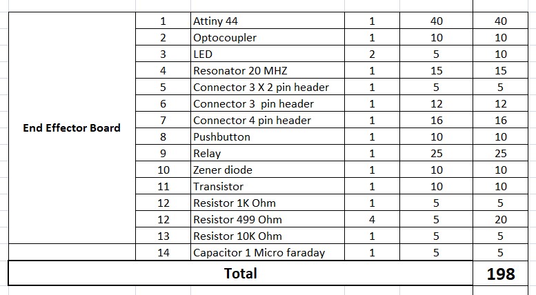
2.End effector board -1 No.
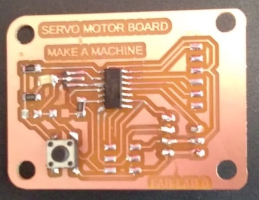
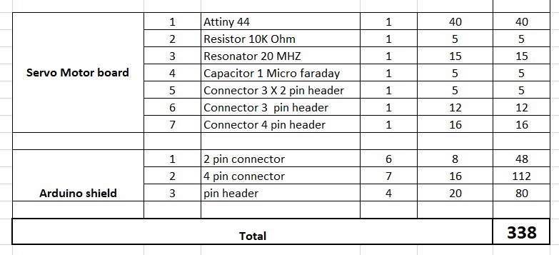
3.Servo motor board-1 No.
4.Shield for Arduino
For electronic part of nema -17 motor board we refer this tutorial
by how to mechatronics.
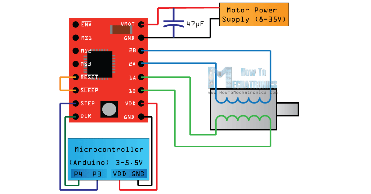
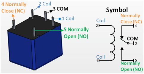
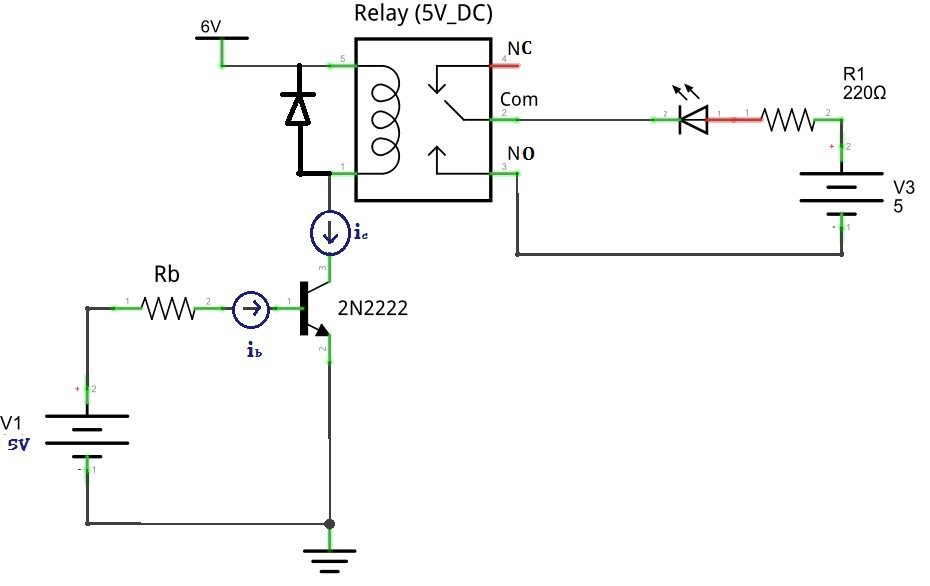
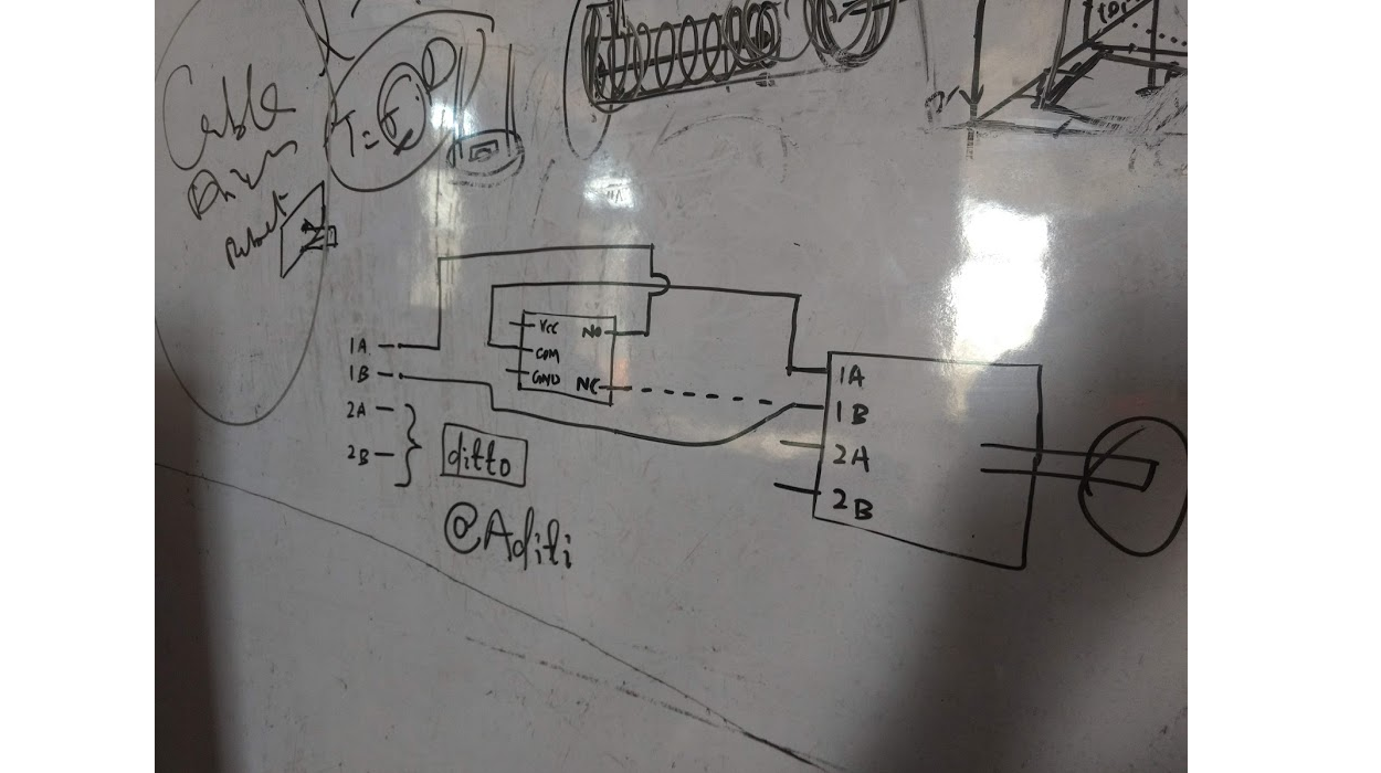
After discussion we concluded that we need some locking mechanism for motor we have driver and motor connections are as follows:
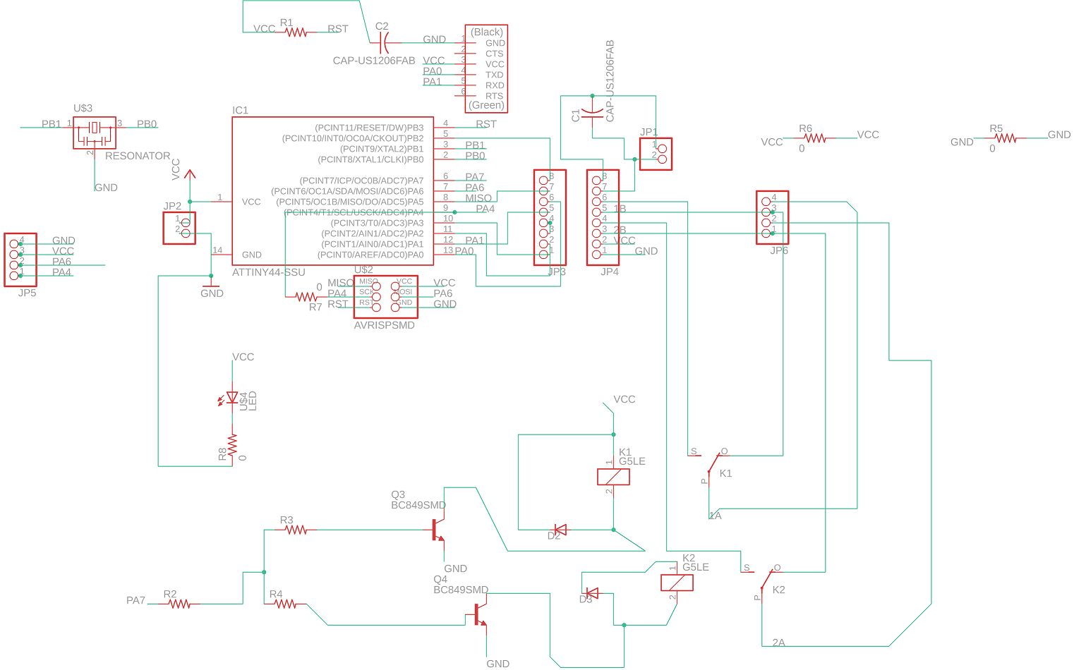
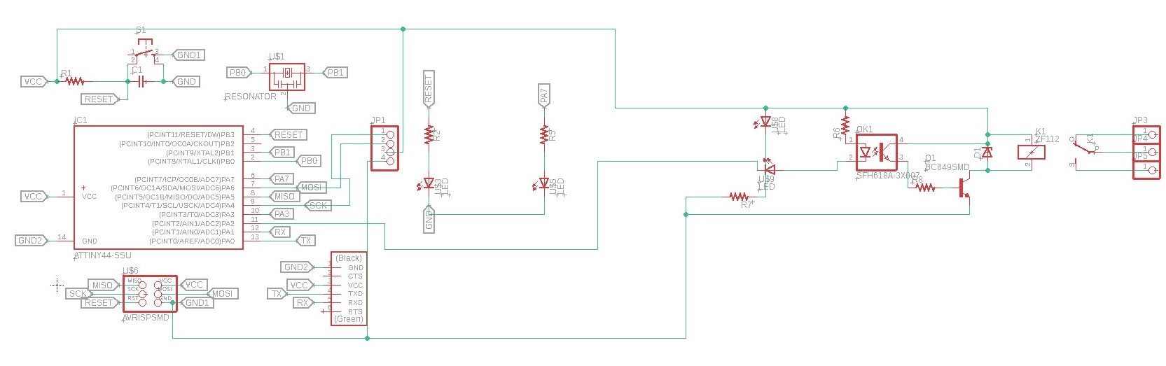
So, Aditi and me designed the board in eagle, the schematic for motor board is like this. We board contains Motor driver, Attiny 44 basic hellow board components, for communicationSCk, SDA (i2c Connector),relay circuit.
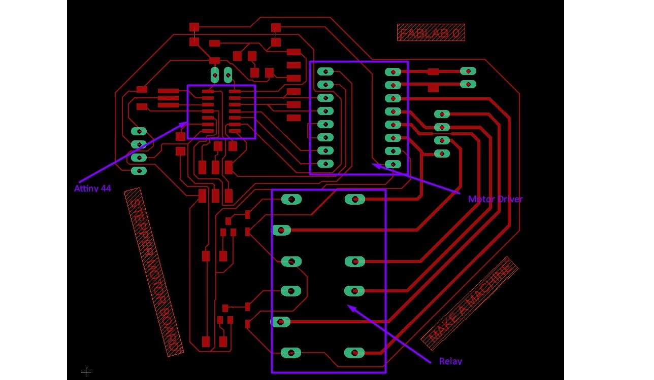
Now the design file from the EAGLE is ready. Next step is to mill the circuit board on SRM 20.
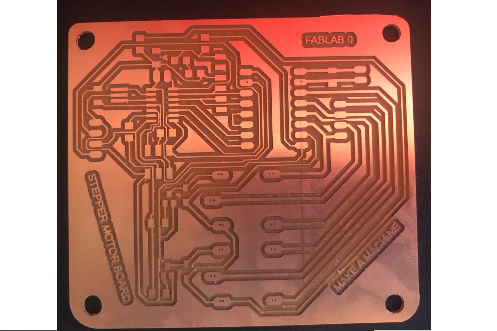
In our first board some tracks were shorted with each other, then we redesign it.
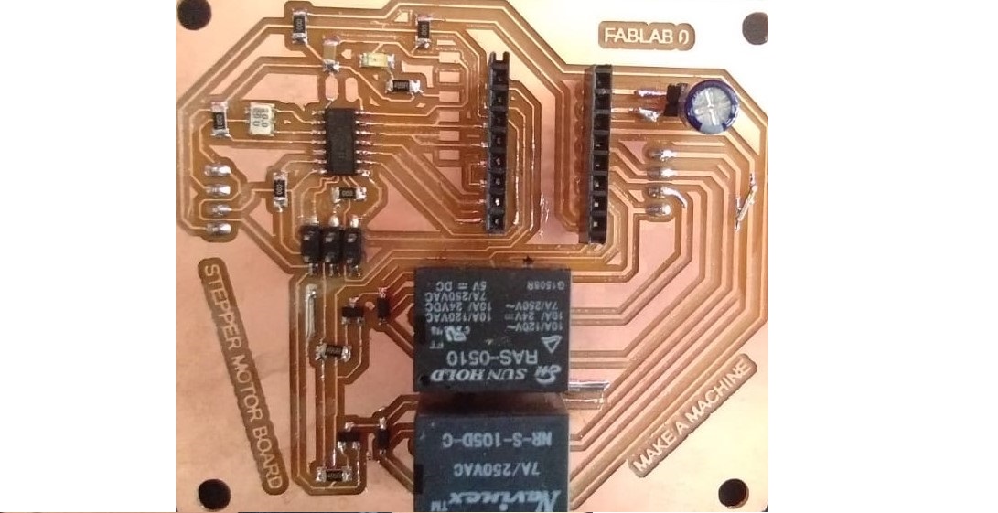
Once the milling is done components are supposed to be soldered on the board. Soldering is being done. Few board is milled and soldered by Jaydeep and few boards are by me.
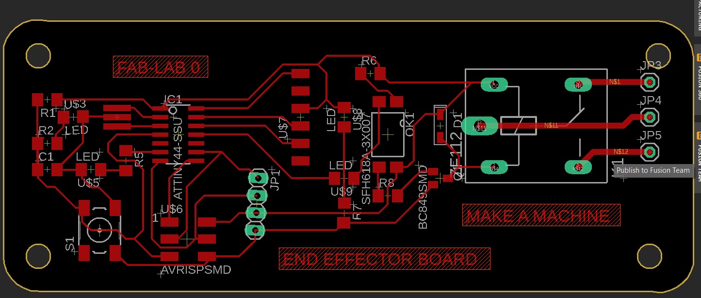
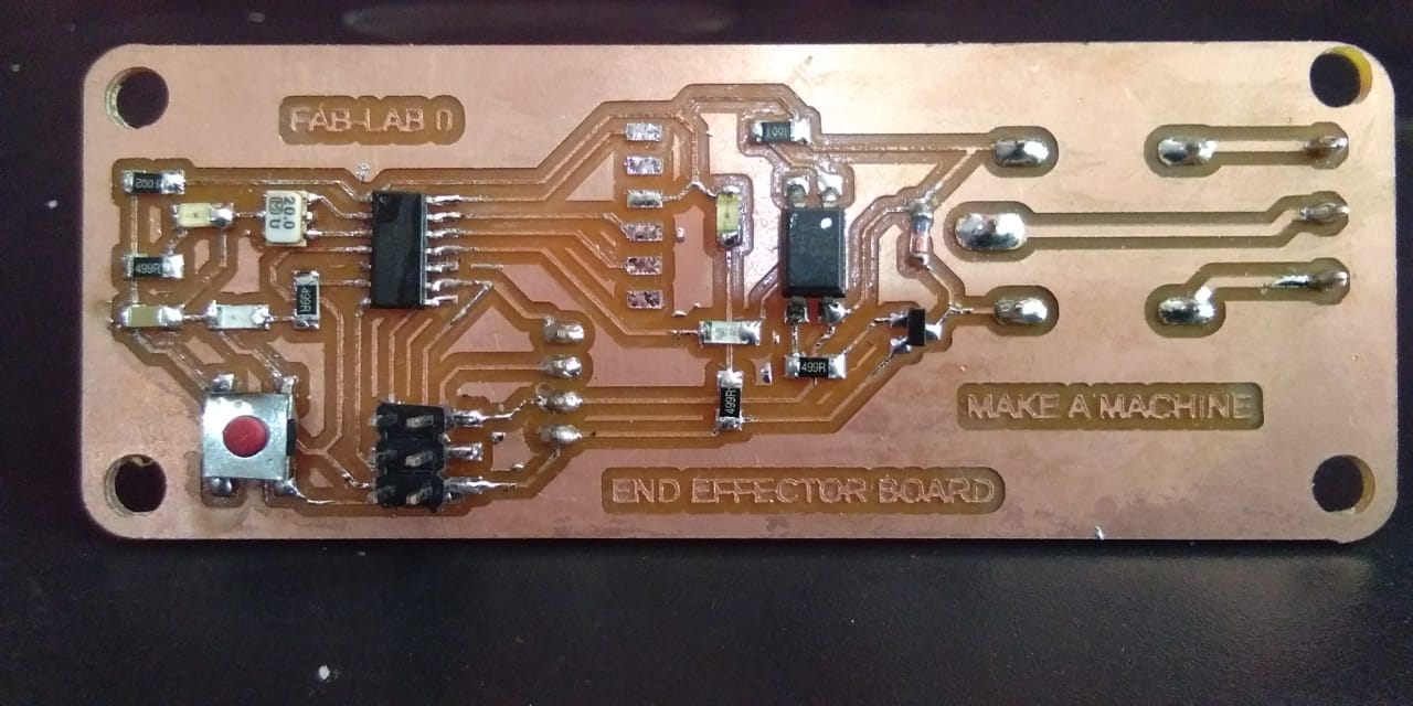
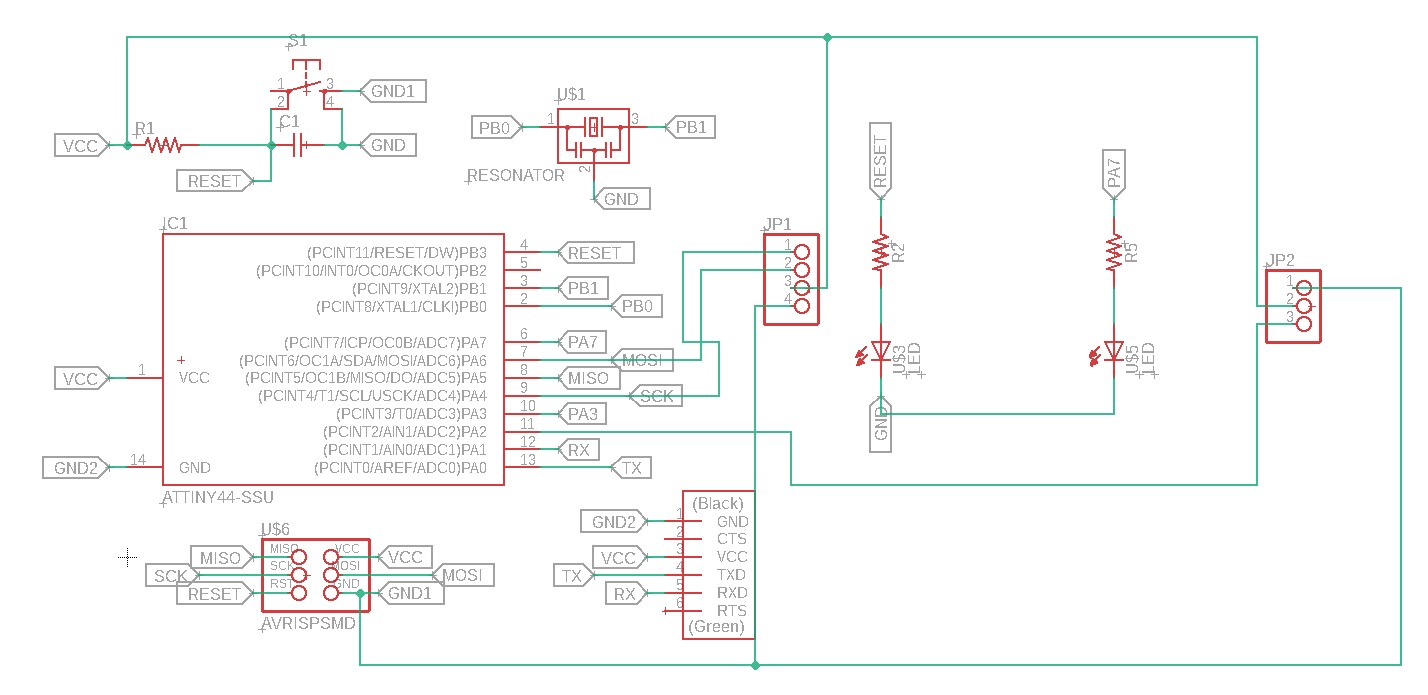
Now the second design is for 'End effector' of Cablebot. Designed in EAGLE is as follow:
The board for end effector this is designed by me, this board consist attiny 44 controller, optocoupler, and simple hello board component.
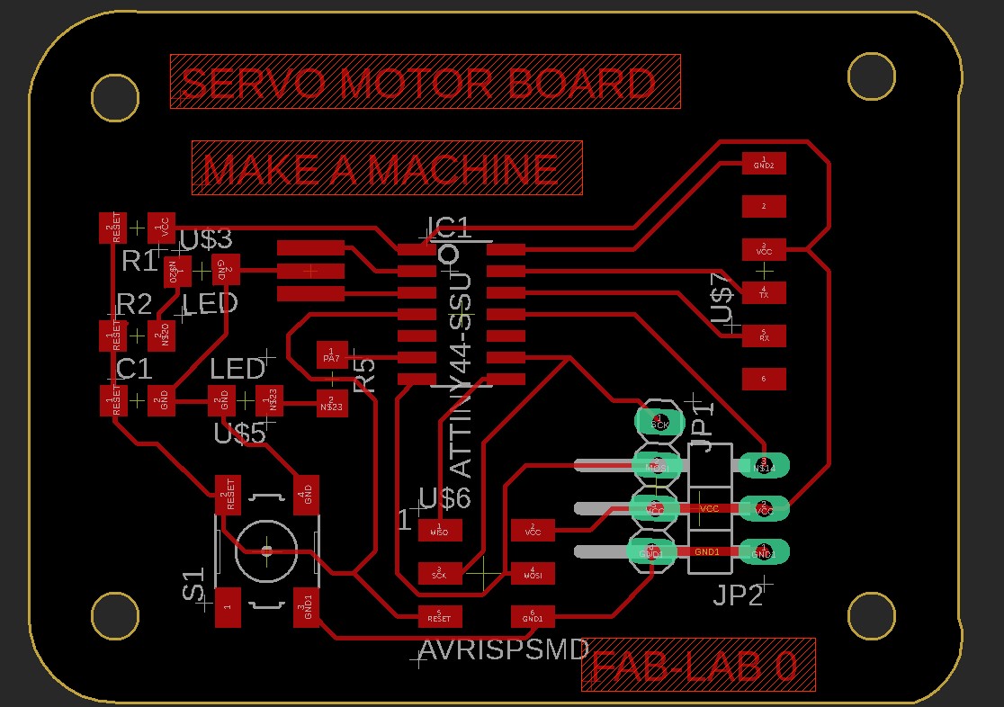
Then 3rd design is very much simple for controlling the servo motor.In this board we used same design of hello board and added 2 connectors of 3 pin headers and 4 pin header for servo motor and communication respectively.
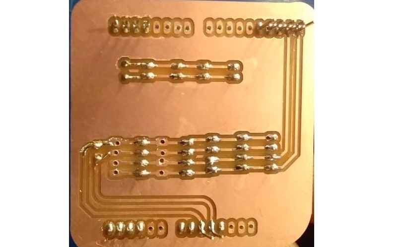
For proper look and presentation to avoid the mess we made shield for master arduino board This board simply conatins the connectors for motor board ,power supply and i2c communication.
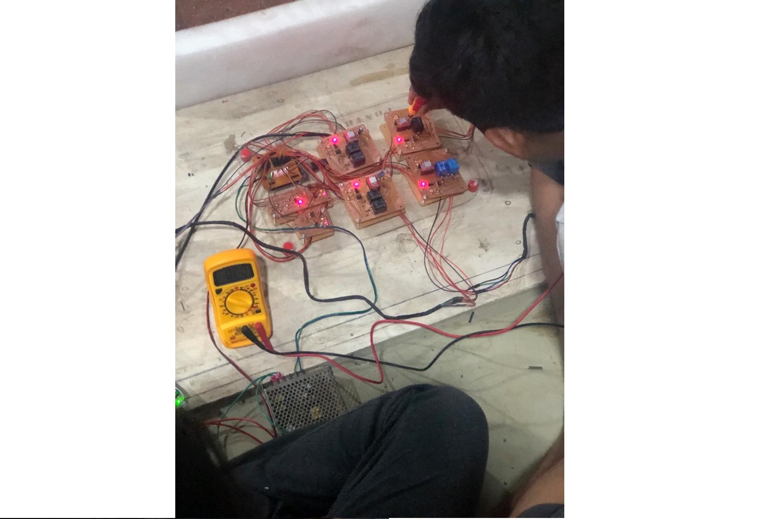
Here, now all electronic control boards are ready as shown in below:
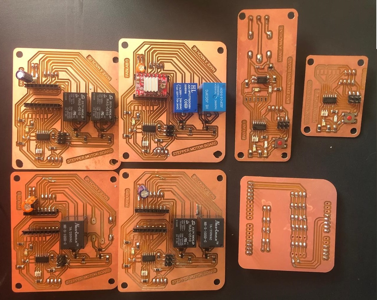
Then Anand made one stand having space for each board on acrylic material on laser cutter. finally we connect all boards and provided 12 v SMPS supply to motor board and 5 V for arduino and other boards.
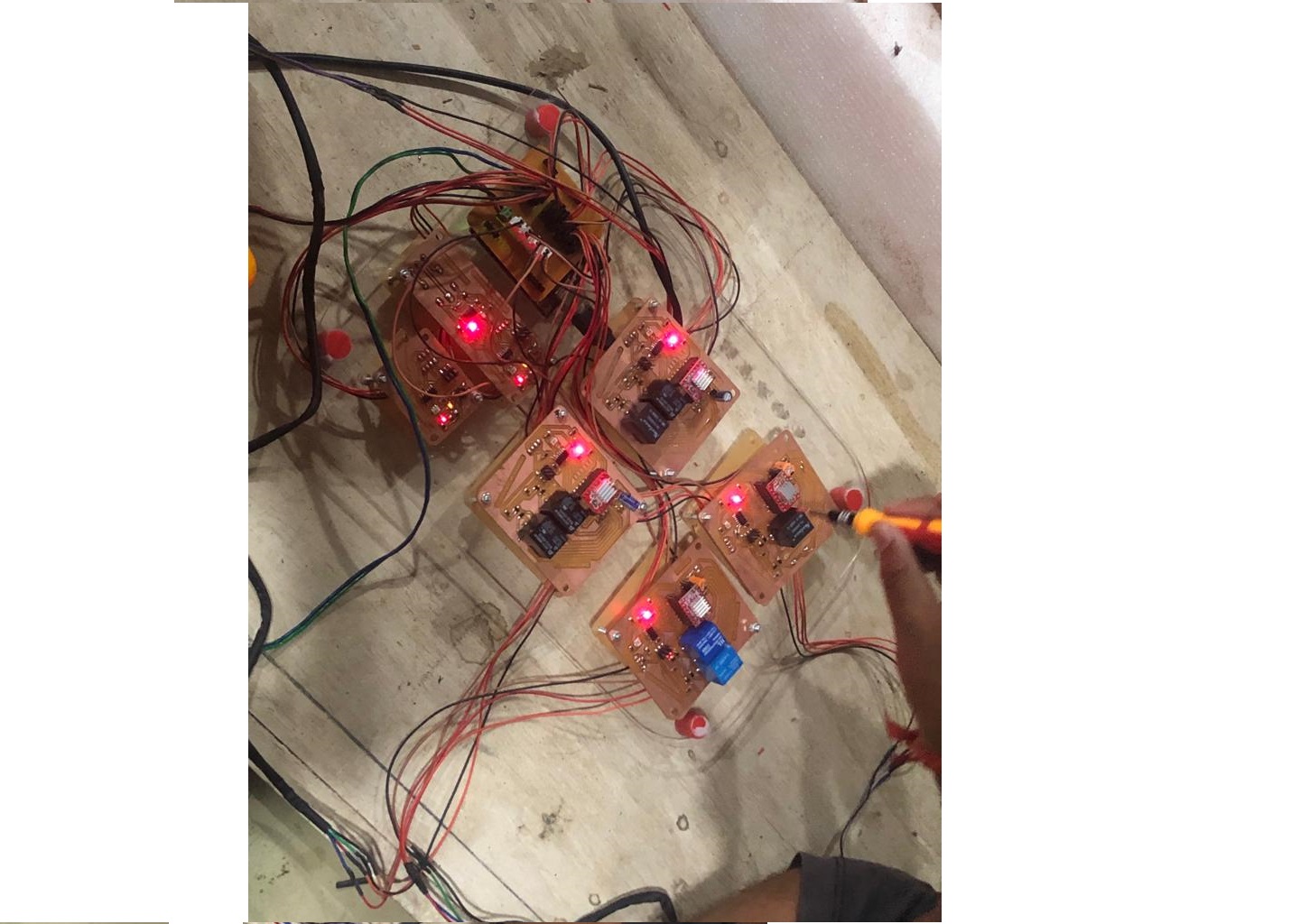
We adjust the resistance as by adjusting the potentiometer knob and we had some issues while soldering the relay so we checked connectivity and how much current is withdraw by circuit we required 6 Amp current for whole system so we are using SMPS of 12 V,10 amp.
Art Gallery:
Electronics BOM:
Design part details are on
Tushar Kukreja,
Pooja Jadhav
For control part and programme details see on
Manoj Sahukar
Learning Outcomes:
1. Leaned How to work with team and work progress is more efficient in team than single person.
2. Understood the process to develope any machine.