Workflow of Assignment:
Group Assignment:
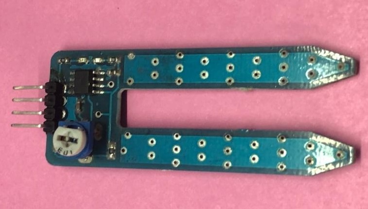
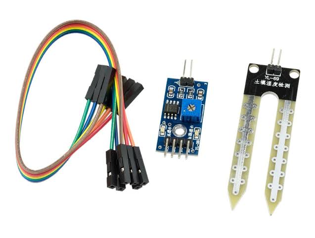
Me and Tushar chose soil moisture sensor to measure analog and digital signals. The soil moisture sensor consists of two probes that are used to measure the volumetric content of water. The two probes allow the current to pass through the soil, which gives the resistance value to measure the moisture value.
Specifications of soil moisture sensor:
1. Input Voltage: 3.3–5V
2. Output Voltage: 0–4.2V
3. Output Signal: both analog and digital
Pin-out of sensor:
1. VCC: Power
2. A0: Analog Output
3. D0: Digital Output
4. GND: Ground
This sensor can be connected in analog and digital modes. First, we connected it in analog mode, and then digital.
1.Analog Read:
When there is water, the soil conducted more electricity, which means that there will be less resistance. Dry soil conducts electricity poorly, so when there is less water, then the soil will conduct less electricity, which means that there will be more resistance.
A.Circuit Diagram:
1. VCC to 5V of the Arduino
2. GND of the sensor to GND of the Arduino
3. A0 of the sensor to A0 of the Arduino
/*
  AnalogReadSerial

  Reads an analog input on pin 0, prints the result to the Serial Monitor.
  Graphical representation is available using Serial Plotter (Tools > Serial Plotter menu).
  Attach the center pin of a potentiometer to pin A0, and the outside pins to +5V and ground.

  This example code is in the public domain.

  http://www.arduino.cc/en/Tutorial/AnalogReadSerial
*/

// the setup routine runs once when you press reset:
void setup() {
  // initialize serial communication at 9600 bits per second:
  Serial.begin(9600);
}

// the loop routine runs over and over again forever:
void loop() {
  // read the input on analog pin 0:
  int sensorValue = analogRead(A0);
  // print out the value you read:
  Serial.println(sensorValue);
  delay(1);        // delay in between reads for stability
}
C. Code Explaination:
Soil sensor input is at pin A0. In the setup function "Serial.begin(9600)" command will help in communcating between serial monitor and arduino. And in the loop function Serial.print() will show value on serial monitor.
D. Setup and Operation:
Three samples of different soil moisture were taken and their values were sensed by soil moisture.
E.Serial Plotter:
Values of different soil moisture were observed on the graph. After changing the sand sample the sensor took a few seconds to show the constant value.
F. Serial Monitor:
Numerical values of soil moisture approx. 185 for sample 1,340 for sample 2 and 642 for sample 3 of sand were displayed on the monitor.
2. Digital Read:
The module also contains a potentiometer, which sets the threshold value. The output LED lights up and down according to this threshold value.
A.Circuit Diagram:
1. VCC to 5V of the Arduino
2. GND of the sensor to GND of the Arduino
3. D0 of the sensor to 2nd Pin of the Arduino
/*
  DigitalReadSerial

  Reads a digital input on pin 2, prints the result to the Serial Monitor

  This example code is in the public domain.
 Modified by Jaydip Sarode
 Date: 2nd OCtober
  http://www.arduino.cc/en/Tutorial/DigitalReadSerial
*/

// digital pin 2 has a pushbutton attached to it. Give it a name:
int pushButton = 2;

// the setup routine runs once when you press reset:
void setup() {
  // initialize serial communication at 9600 bits per second:
  Serial.begin(9600);
  // make the pushbutton's pin an input:
  pinMode(pushButton, INPUT);
}

// the loop routine runs over and over again forever:
void loop() {
  // read the input pin:
  int buttonState = digitalRead(pushButton);
  // print out the state of the button:
  Serial.println(buttonState);
  delay(1);        // delay in between reads for stability
}
C. Code Explaination:
Pin 2 of arduino has been defined as pushbutton. 1 millisecond of delay is in between reads for stability.
D. Setup and Operation:
The 3rd sample in this case has been replaced by water to give maximum conductivity. The first and second sample as same as above experiment. In the 3rd sample Blue Led lights up showing it has reached maximum vale.
E. Serial Plotter:
Digital Read gives output value only in 0 or 1. There is no inbetween value which is clearly visible on the graph.
F. Serial Monitor:
The 3rd sample of water gave value 1. First and second sample even though had certail soil moisture the output is shown 0.
Individual Assignment:
Input device
An input device is a piece of hardware used to provide data to a micro-controller used for interaction and control. It allows input of raw data to the computer for processing. Input devices are also called as 'Sensors'.
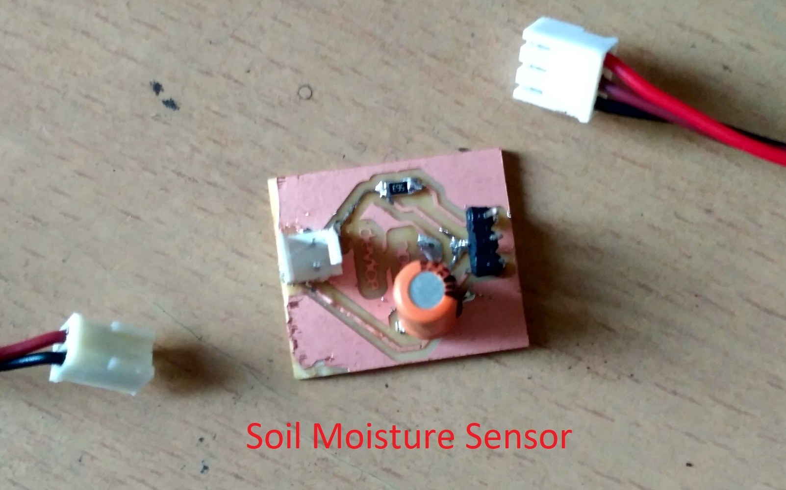
After completing this week group assignment my instructor commented that, this soil moisture sensor is not durable. After a few days time, the readings are not accurate. So, I took-up this challenge for this(input) week individual assignment and I decided to redesign the and probe for 'Soil Moisture' measurement.
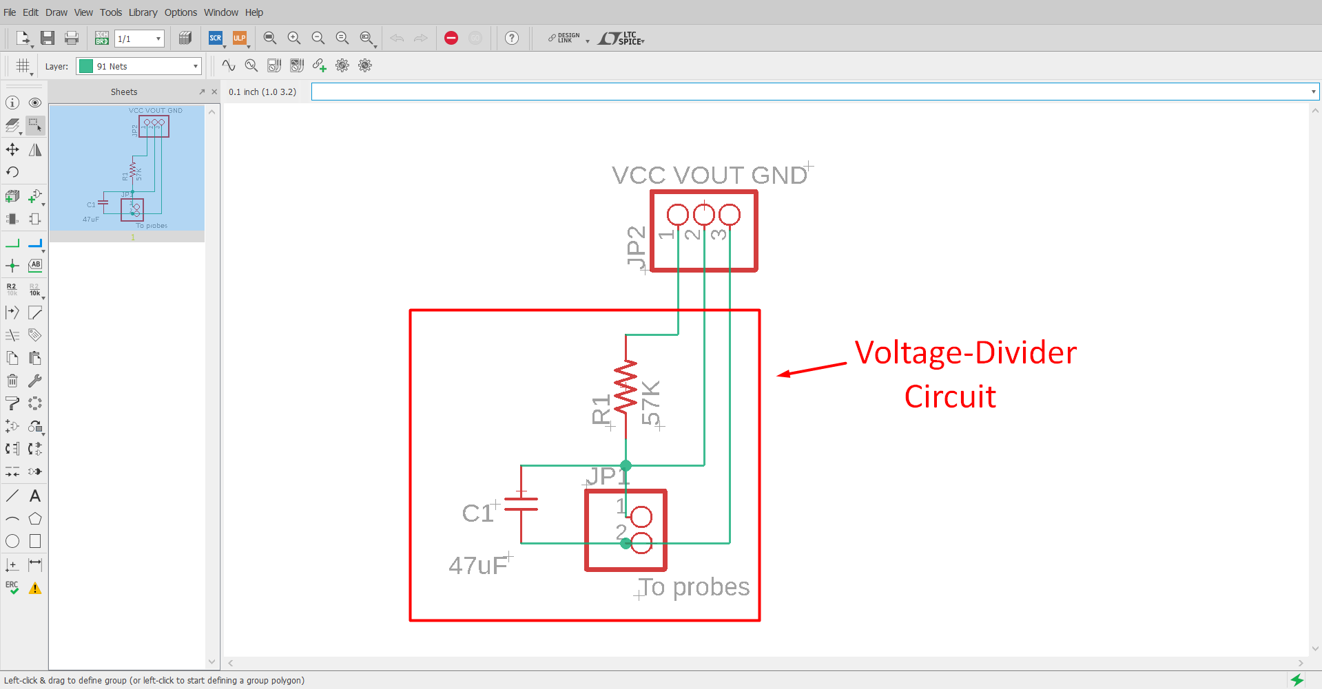
I sketched a simple 'Voltage-Divider' circuit for soil moisture moisture measurement is shown in below:
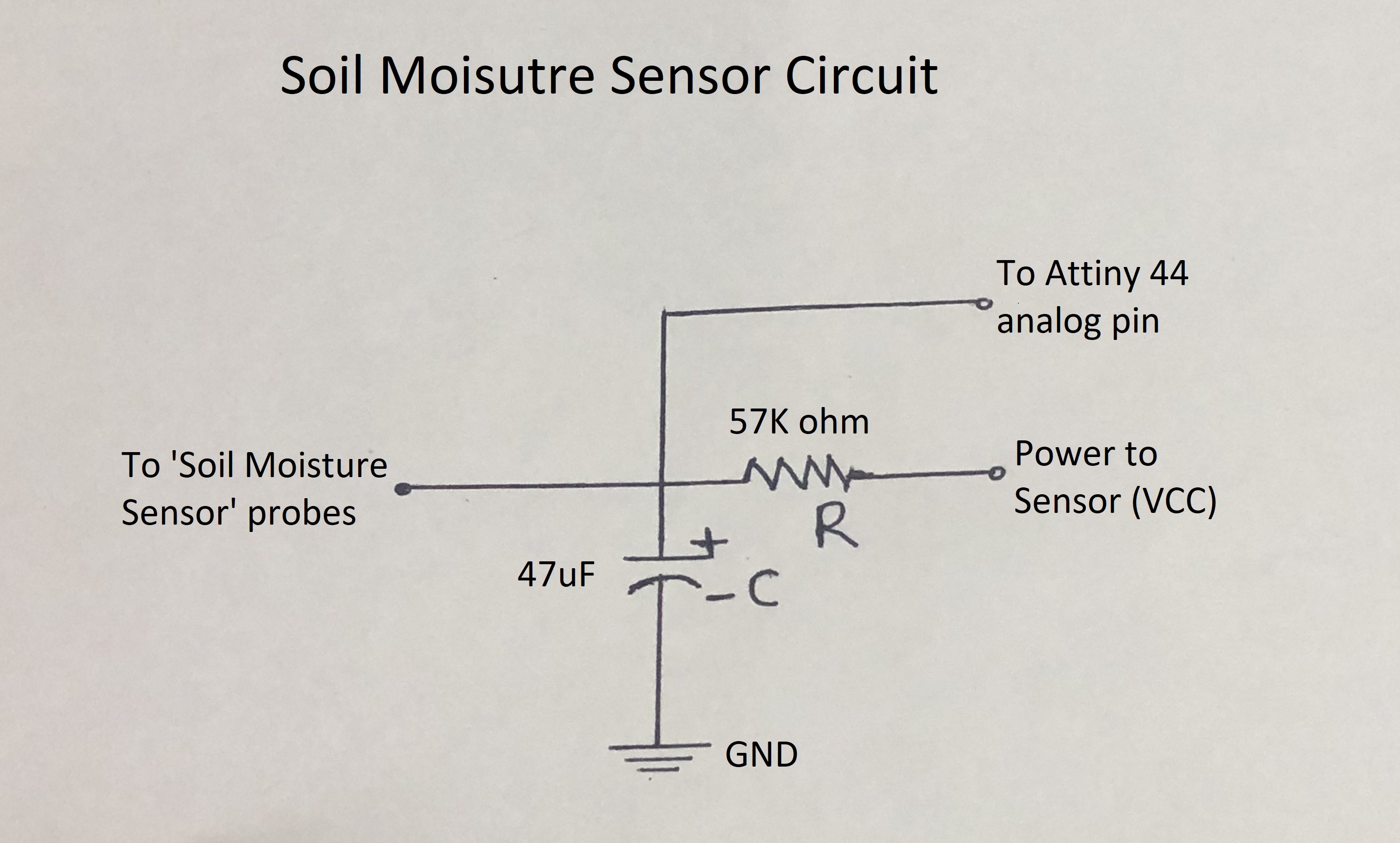
The circuit is mainly a voltage divider - the soil moisture sensor is one half and the 57k ohm resistor is the other half.
There is also a noise filter - the 47uF capacitor going to ground. And of course, an output so the 'Attiny 44' can take a sensor reading.
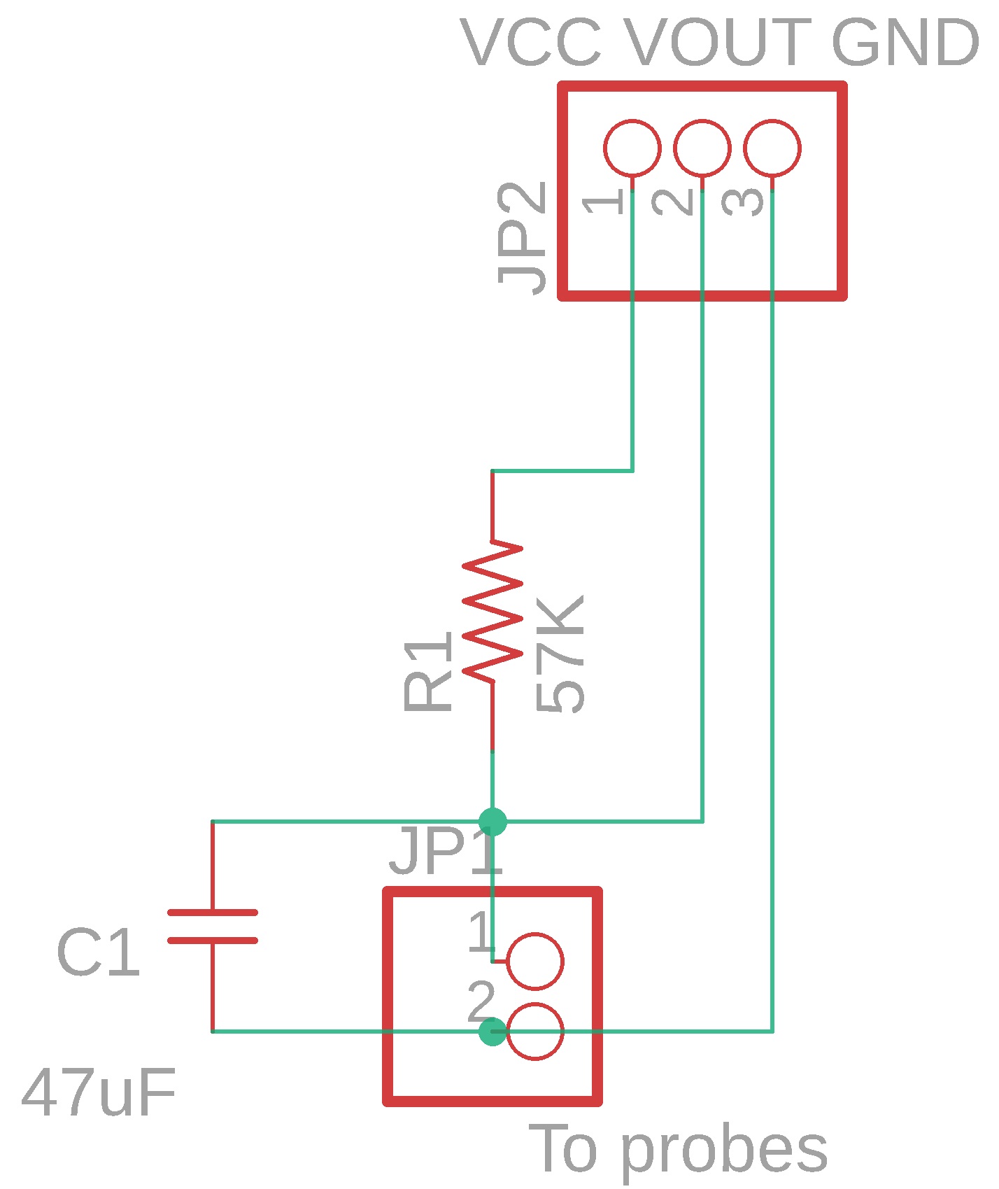
Circuit Designing:
Now, I'm going design above circuit in 'Eagle' software. Circuit diagram is shown in below:
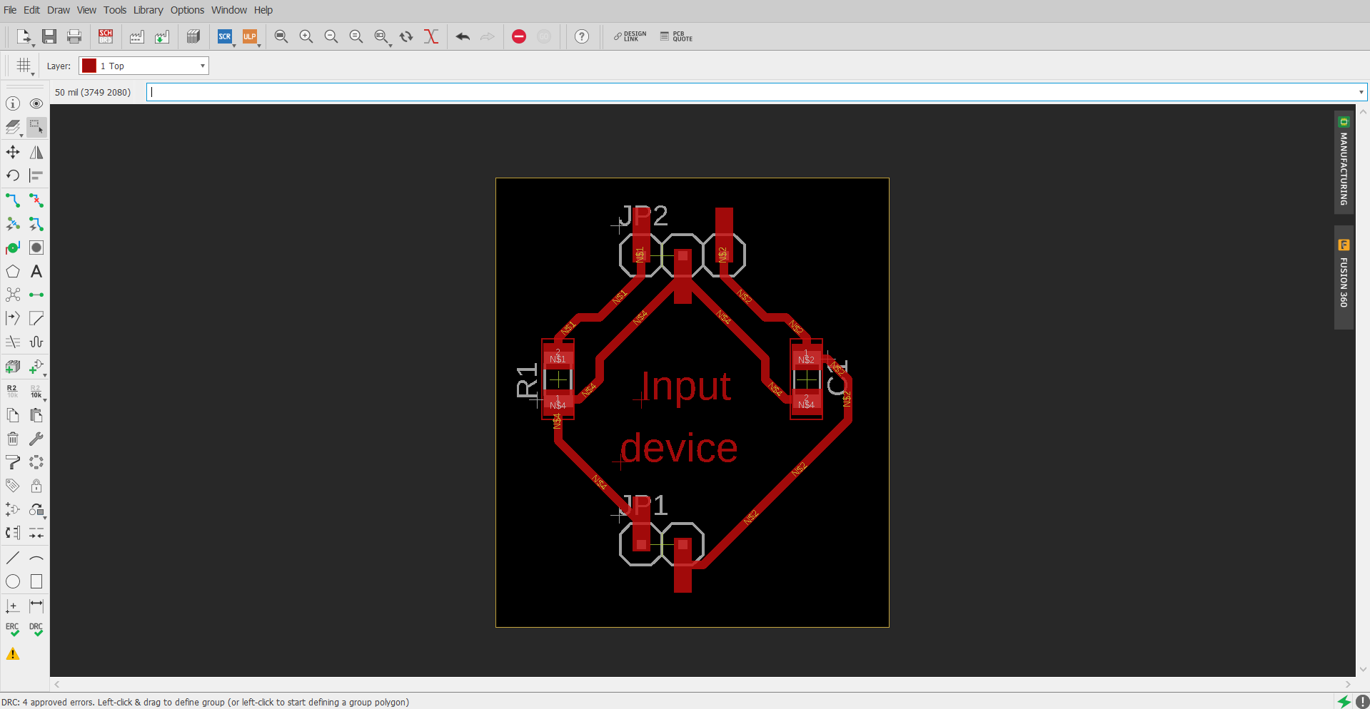
Next step is the 'Switch to Board'. Then I done manual routing and this way complete my board design is shown in belwo:
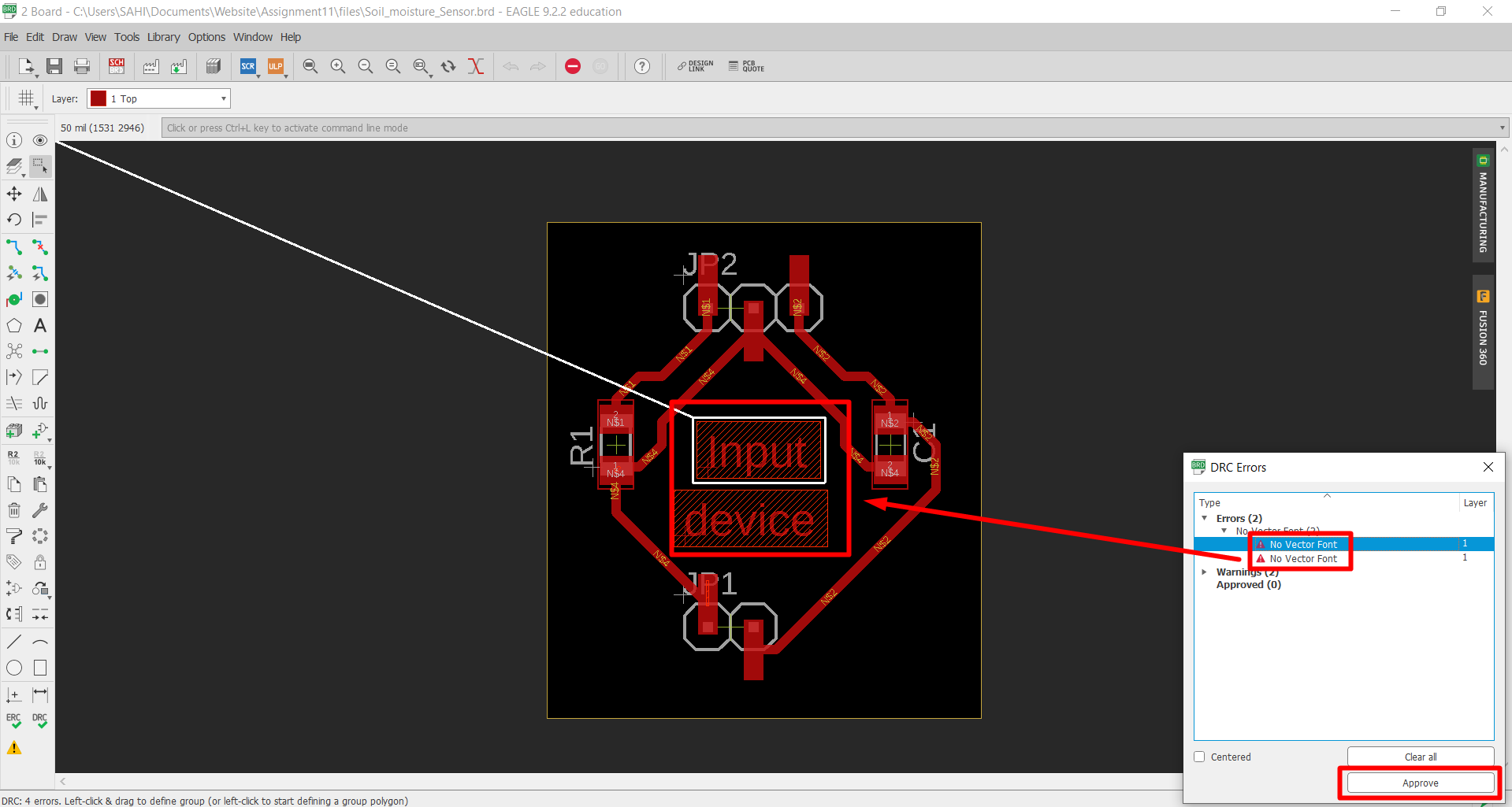
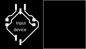
Next step is the export monochorme '.PNG' image for milling board.
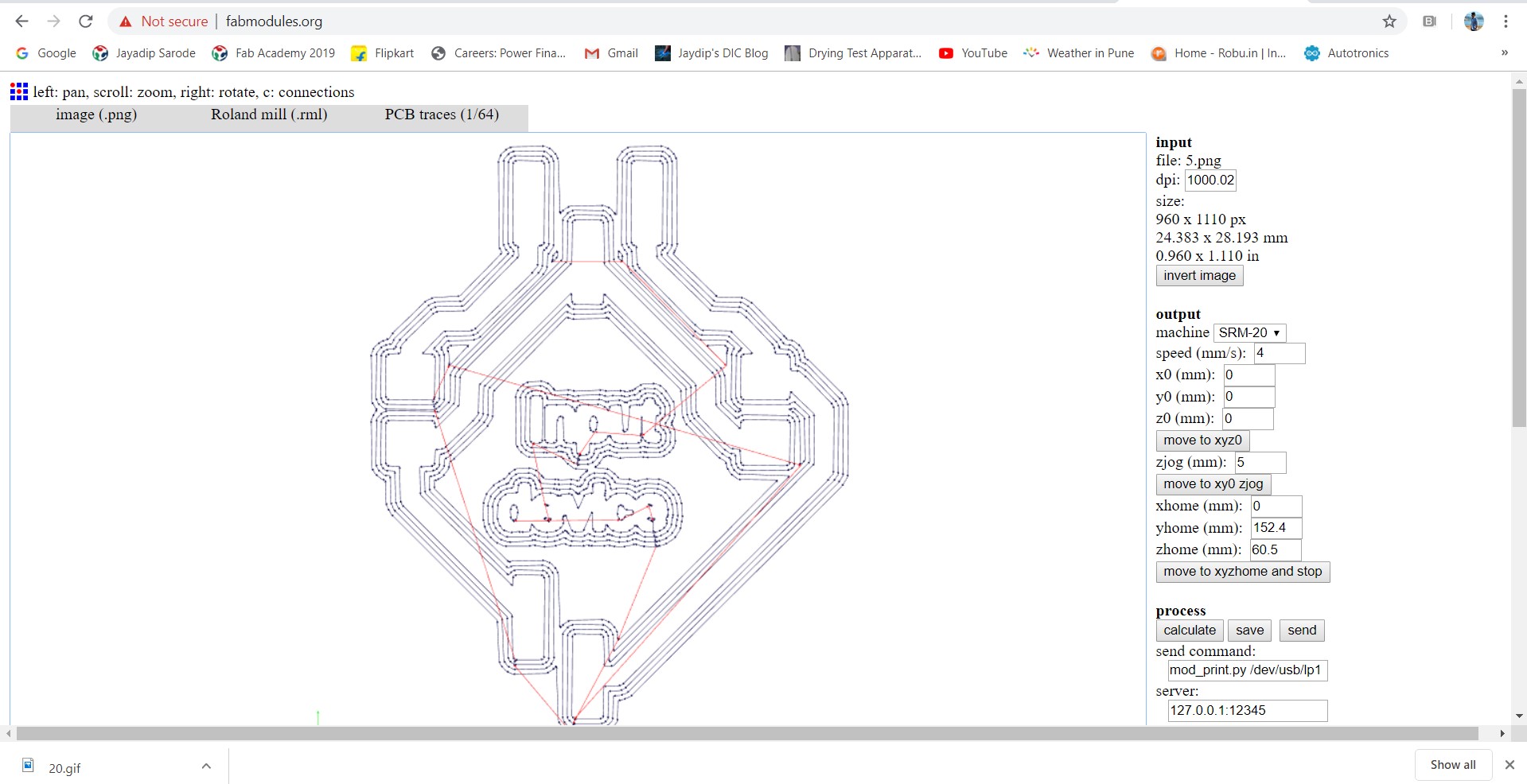
Now, I'm going to make '.rml' for milling my sensor board on SRM-20 milling machine.
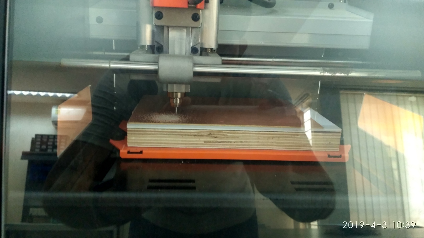
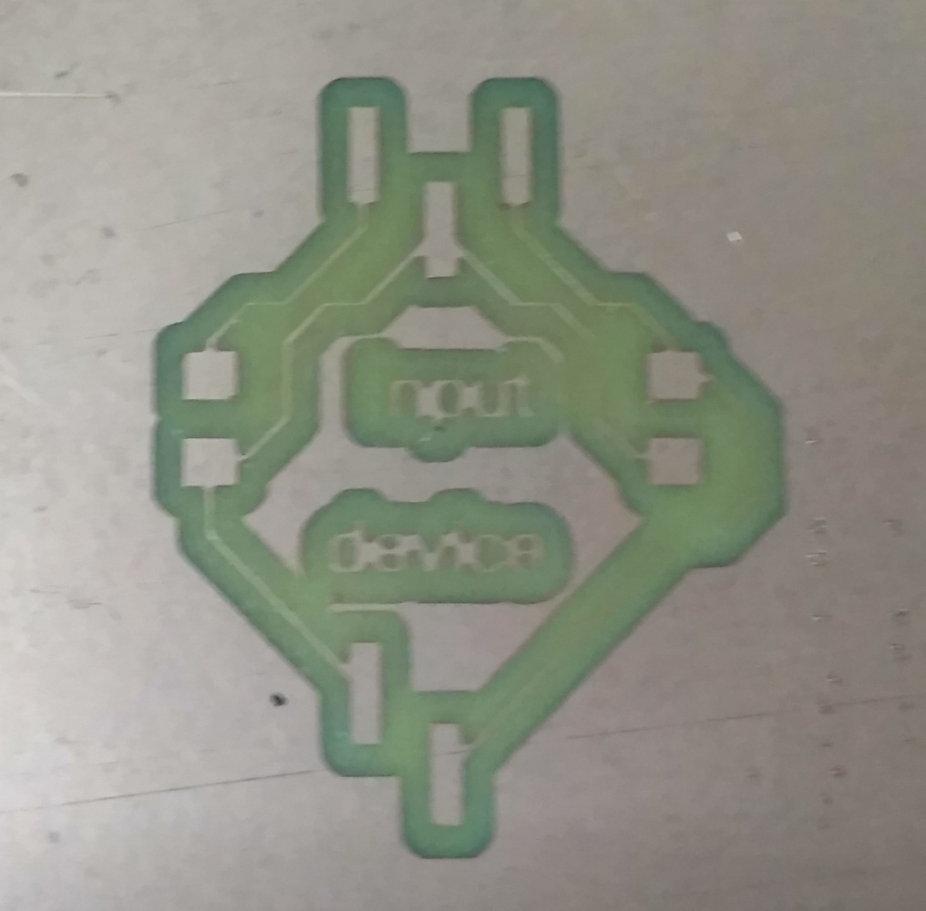
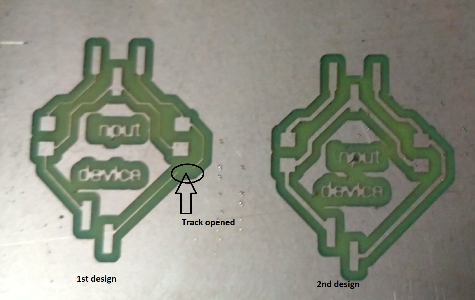
After completing milling work of board, but there is a one problem. I was set track-width '6 mill' while designing the board. So, I again modify the 'track width' and give traces cut again. Poblem is that 'tack was broken during milling' as shown in below:
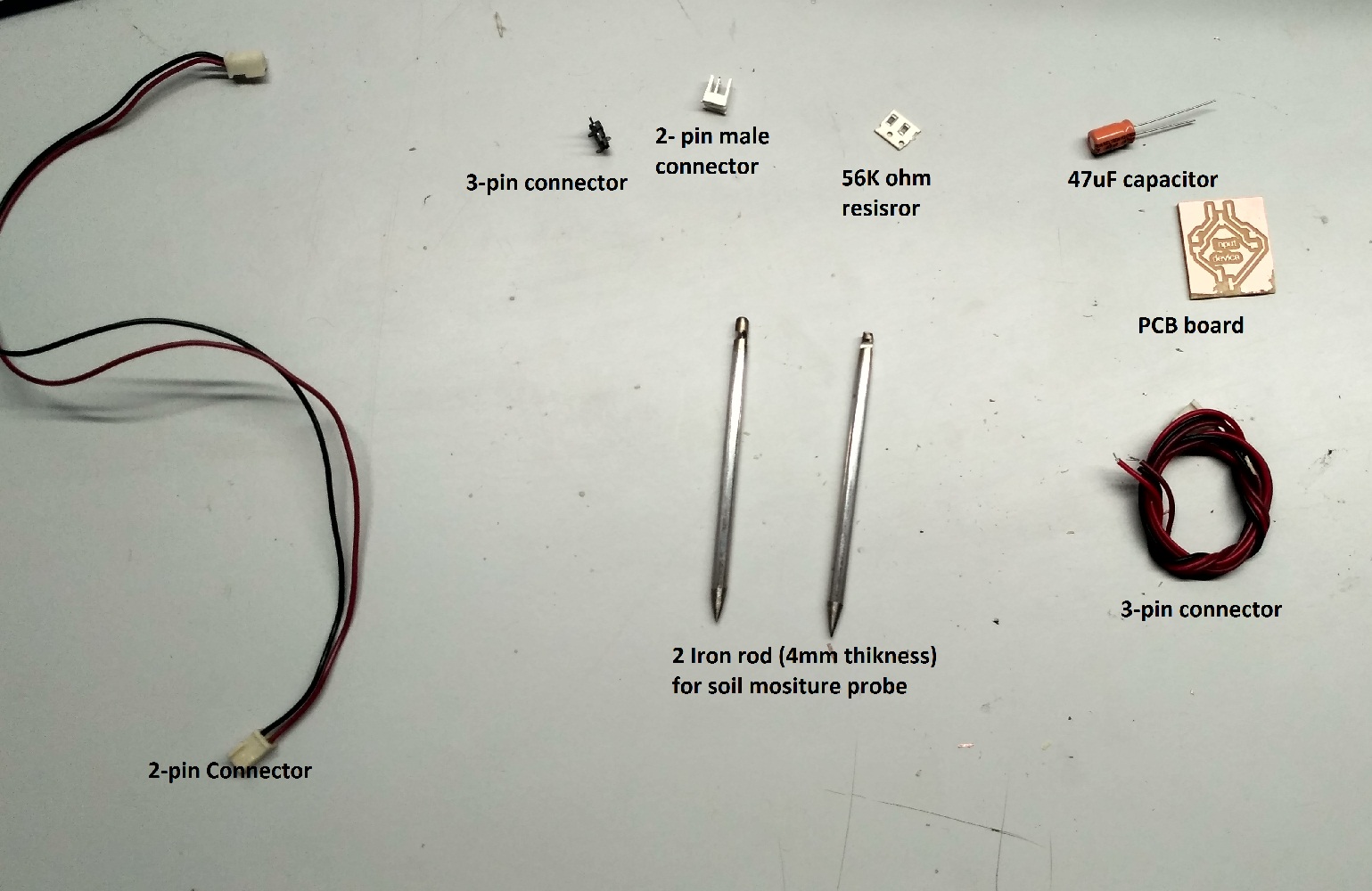
After milling board, next step is the soldering. Then I collected all the components which are need for my board.
The needed components are listed below(and shown in below):
1. 57k ohm resistor
2. 47uF capacitor
3. 2-pin male connector
4. 3-pin pinhead
5. 3-pin female connector with wire
6. 2-pin female connector with wire
7. 2 Stainless-steel rod (4mm thickness) for soil moisture probe
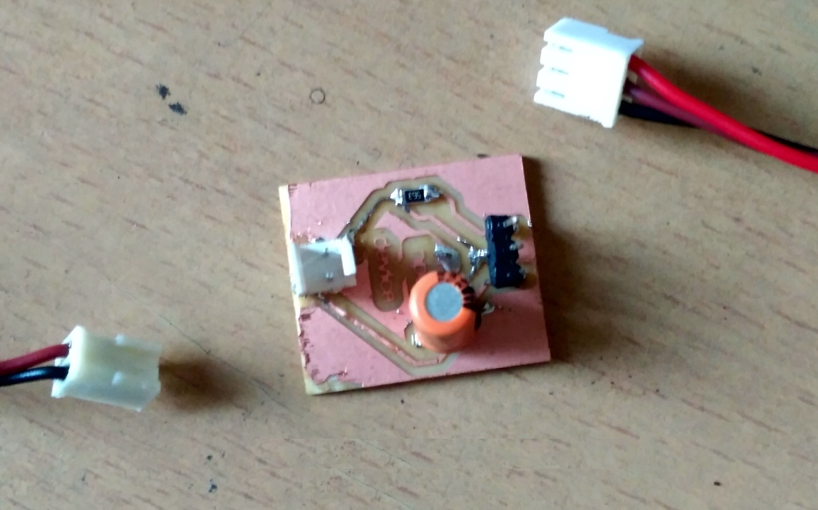
After completing soldering, my board as shown in below:
Coding:
1. Code for soil moisture sensor, when sensor interfaced with Attiny 44 uC and it gives LED indication:
/*
 Created 2019
 By jaydip Sarode
Fab Academy
*/

const int sensorPin = PA1;  //define a pin for analog input from soil moisture sensor
const int greenledPin = PA7; //define a pin for LED

void setup()
{
   pinMode (sensorPin, INPUT); // Set sensorPin is input pin

 pinMode(greenledPin, OUTPUT); // Set greenledPin is output pin

}

// the loop routine runs over and over again forever:
void loop()
{
  int sensorValue = analogRead(sensorPin); // read the input on analog pin PA1 which connected to analog ouput of Soil moisture sensor

/*
 Total analog step= 1024(i.e.0 - 1023)
 and 768 is the 75% of 1024.
 So, 1023-768= 255.
  When 75% water available in soil, sensorValue is "255"
  When 50% water available in soil, sensorValue is "511"
  When 25% water available in soil, sensorValue is "768"
  When 0% water available in soil, sensorValue is "1023"
 */

 if (sensorValue<255)    //If water available in soil is more than 75%
     {
       digitalWrite(greenledPin, HIGH);  //Green led will be turn ON, when 75% water avialble in the soil.
      }
  else
    {
     digitalWrite(greenledPin, LOW);  //Green led will be turn OFF, when water below the 75% in soil.
     }
  delay(1000);        // 1 second delay in between reads for stability
}
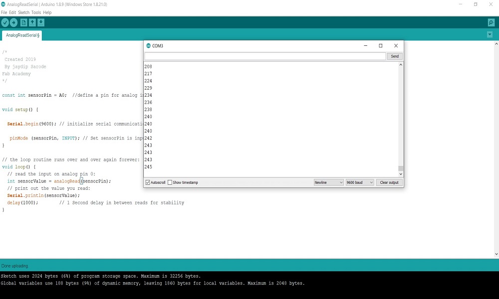
2. Code for soil moisture sensor, when sensor interfaced with Arduino Uno and it gives serial monitor output:
/*
 Created 2019
 By jaydip Sarode
Fab Academy
*/

const int sensorPin = A0;  //define a pin for analog input from soil moisture sensor

void setup() {

  Serial.begin(9600); // initialize serial communication at 9600 bits per second:

   pinMode (sensorPin, INPUT); // Set sensorPin is input pin
}

// the loop routine runs over and over again forever:
void loop() {
  // read the input on analog pin 0:
  int sensorValue = analogRead(sensorPin);
  // print out the value you read:
  Serial.println(sensorValue);
  delay(1000);        // 1 Second delay in between reads for stability
}
Testing:
1.
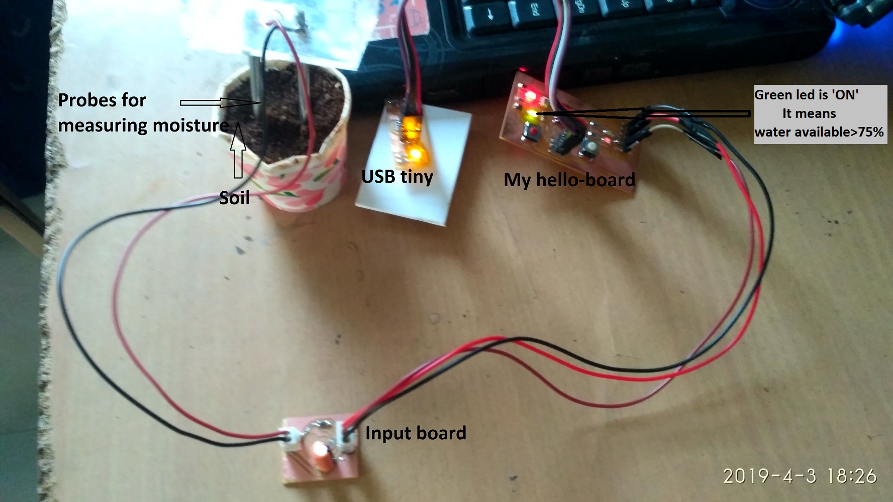
Next step is testing. I tested my input (soil moisture sensor) board which is interfaced with my helloworld board (44uC). My helloworld didn't support to serial monitor because, Attiny 44 uC havn't 'Rx' and 'Tx' pins. So I used LED indication for testing my input board. I have a green led connected to PA7 pin of Attiny 44 uC in my Helloworld board.
Green LED will turn ON, when soil moisture is greater than 75%, Otherwise it will be 'OFF'. Now, Green LED is 'ON' it means moisture is more than 75%, as shown in below:
2.
Now, I interfaced my input (soil moisture sensor) board with 'Arduino Uno' for observing sensor's value on Serial monitor, as shown in below:
Learning Outcomes:
1. Leaned sensors working principle and operaions.
2. Understood calculations regarding sensor design.