Workflow of Assignment:
Output Devices:
An output device is any piece of Embedded hardware systems which converts information into human-readable form or an actuators.
Group Assignment:
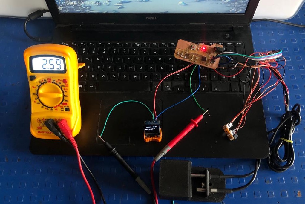
The OLED displayed temperature and humidity data. Of the 4 pins GND, VCC, SCL and SDA the multimeter was connected inbetween the VCC wire connection. The current from source passed through multimeter and reached OLED. Here, the multimeter displayed the value of current 2.59 milli Ampere.
2. Calculations:
Volatge supplied to OLED from the source=5V
Current reading in multimeter=2.59mA
Power = voltage x current
Power= 5x2.59 mAV
Power=12.95 milliwatt
Individual Assignment:
Considering the final project, I wanted something to be operated on AC supply. But the microcontroller board needs DC supply, so it was a challenge to make such circuit. I realized relay is such a device which could isolate.
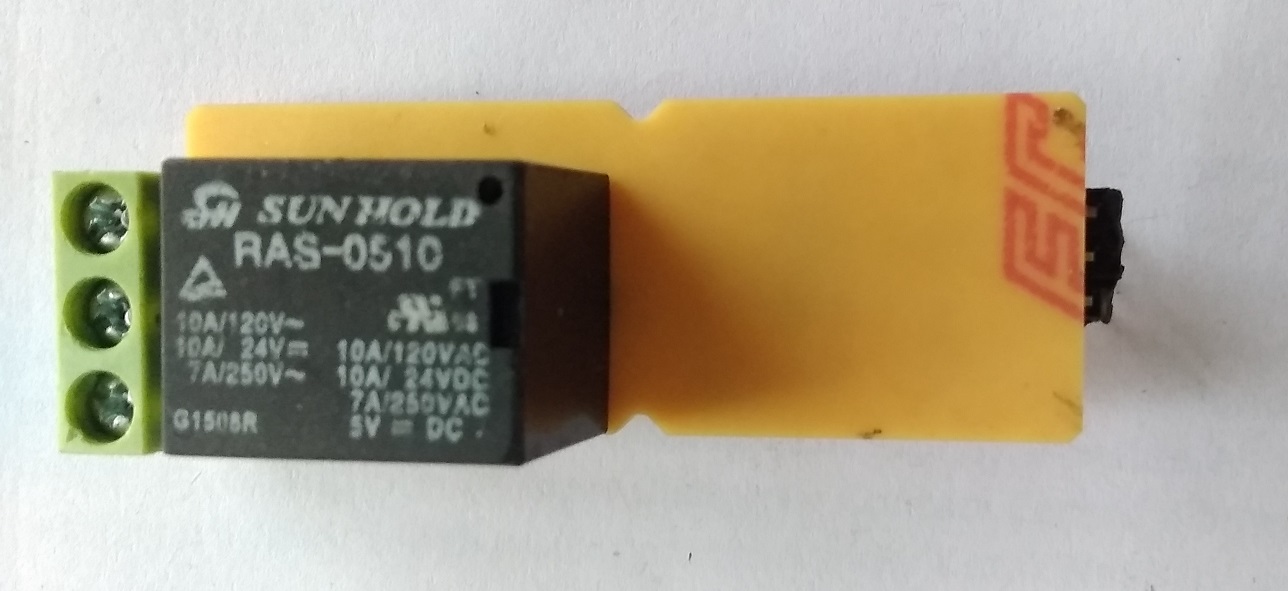
So In this week a relay board is supposed to be designed.
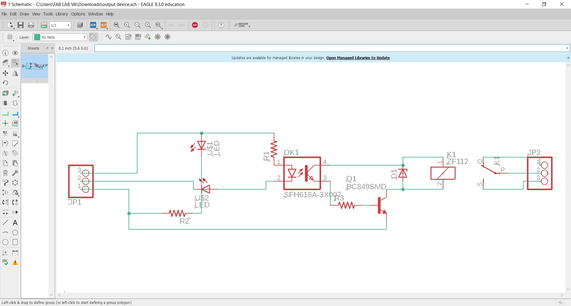
The next step is to design this relay board in EAGLE software. The required components are listed down below:
1. 5v relay
2. Isolator 817
3. Zener diode
4. NPN transistor
5. LED and Resistor
6. 3 pin Male header
7. 3 pin connector
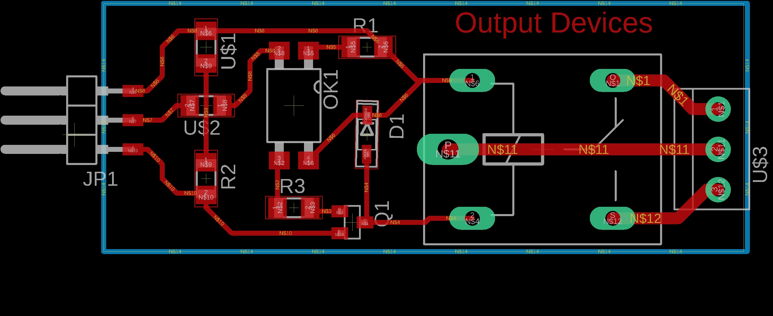
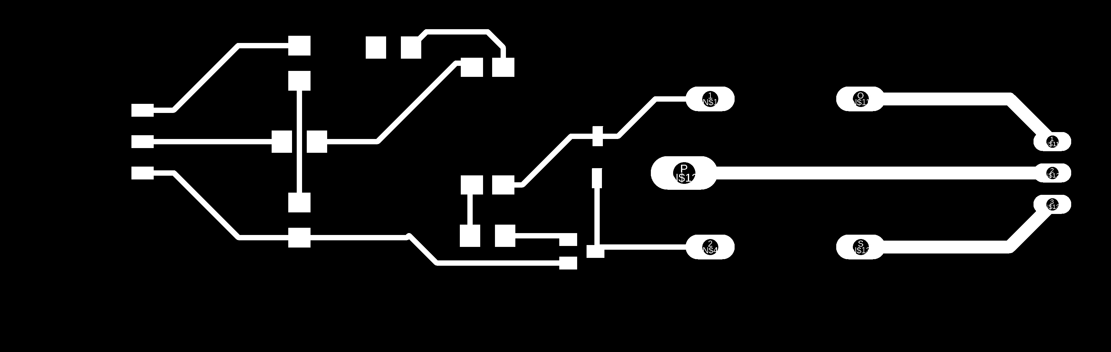
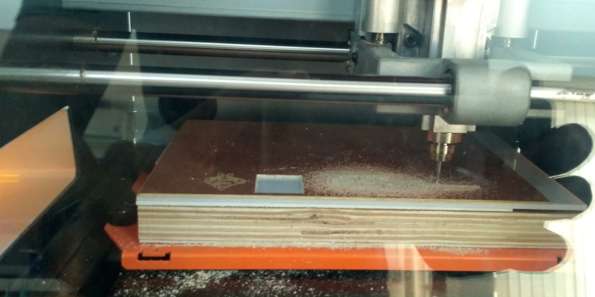
Now the design file from the EAGLE is ready. Next step is to mill the circuit board on SRM 20.
Once the milling is done components are supposed to be soldered on the board. Soldering is being done.
Connections :
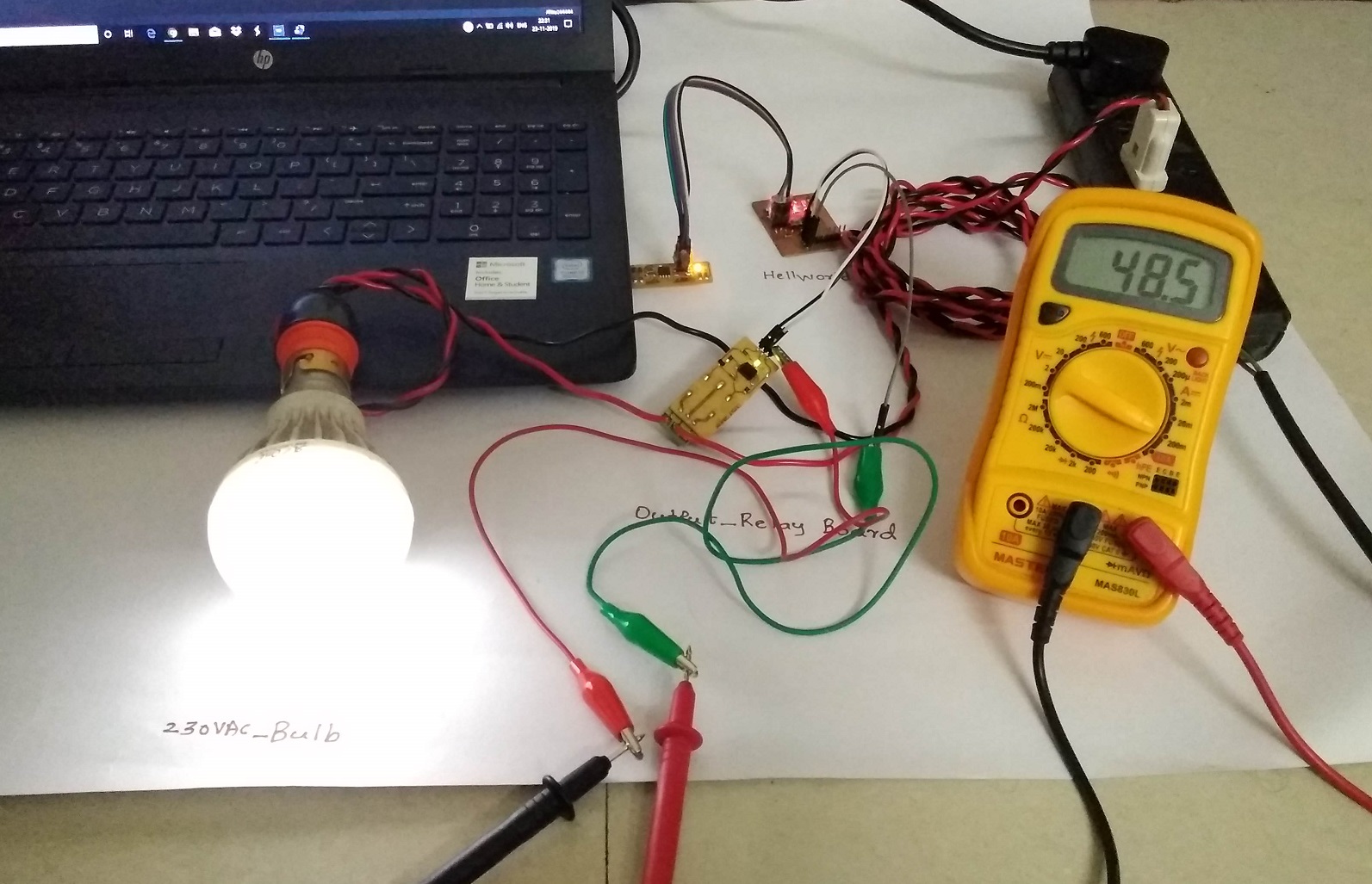
Once all the components are soldered the board is ready to test now. Now going for make connections and testing.
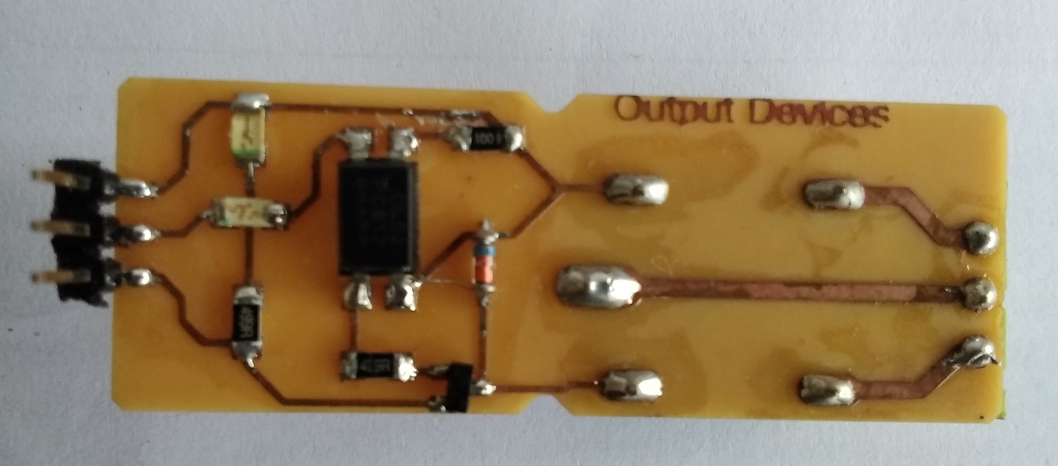
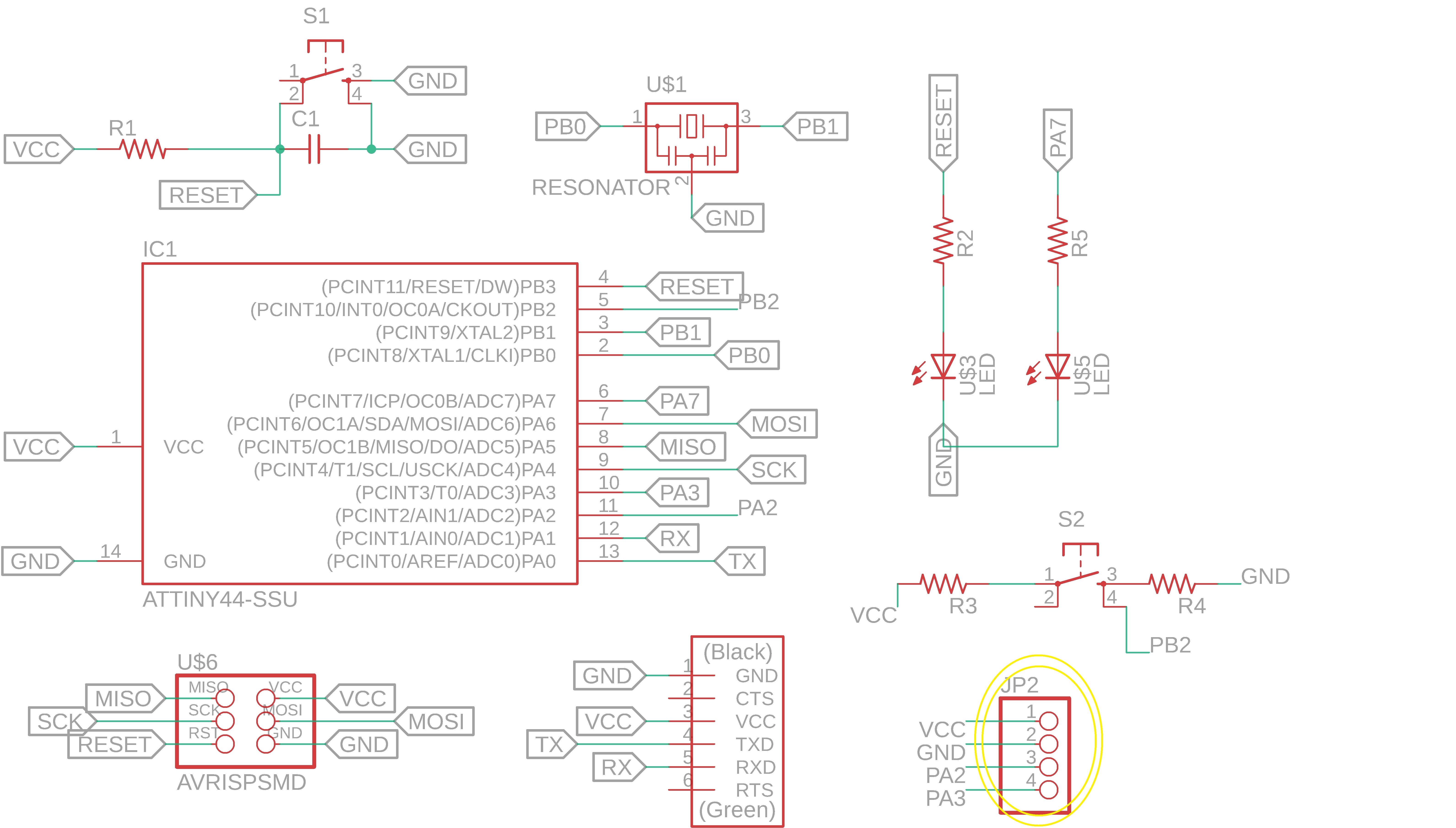
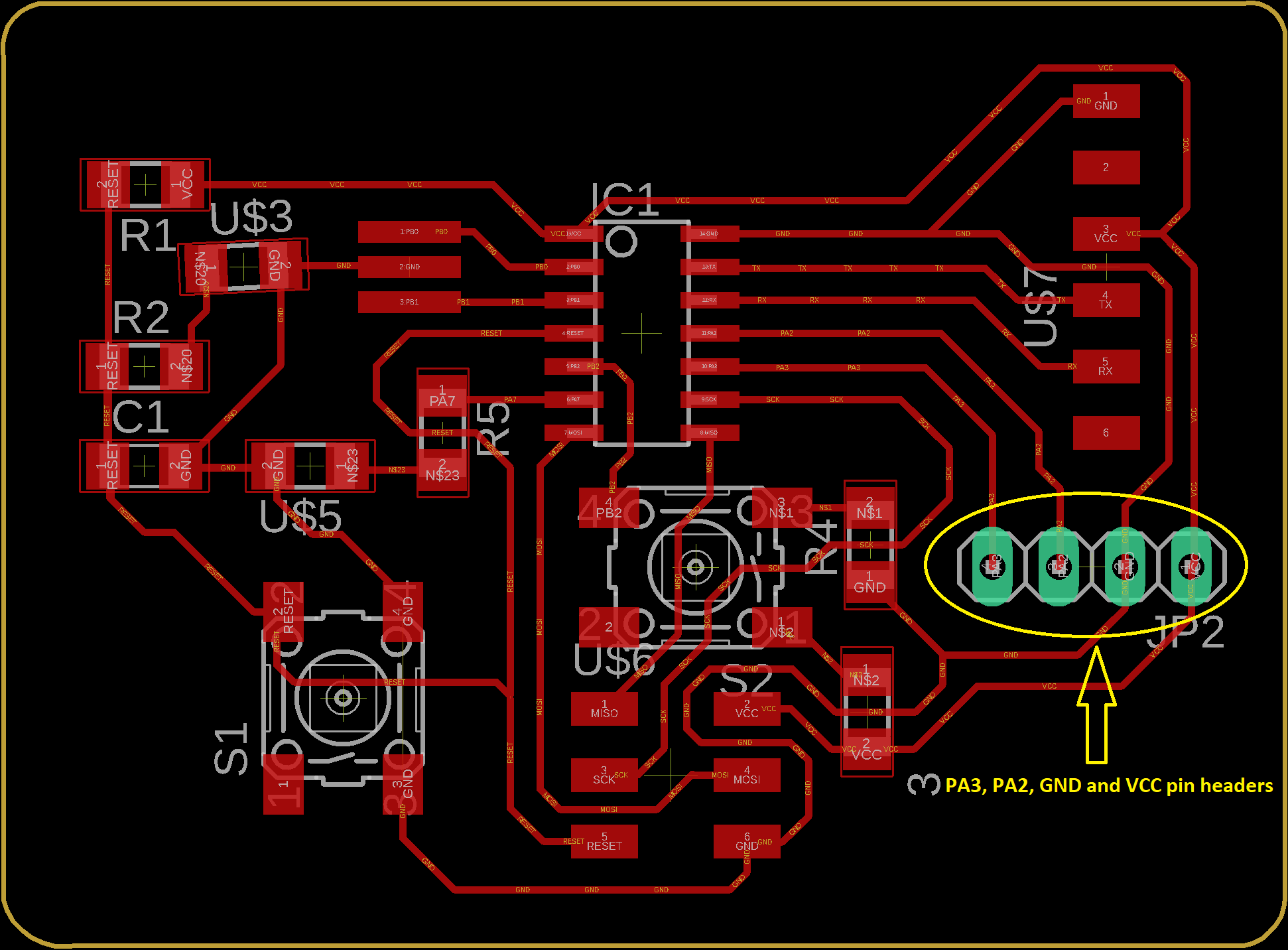
I used my helloworld board for this week i.e.'Output Devices'. I had already added 4-pin male header(PA3, PA2, VCC and GND) and the digital pin 'PA2' of Attiny 44 uC is connected to the relay board input pin as shown in above image.
My helloworld board design as shown in below:
Coding :
/*
Created 2019
Jaydip Sarode
Fab academy
*/

const int relayPin = PA2;  // define a pin for digital output to Relay board

void setup()  // the setup function runs once when you press reset or power the board
{
  pinMode(relayPin, OUTPUT);  // initialize digital pin LED_BUILTIN as an output.
}

void loop() // the loop function runs over and over again forever
{
  digitalWrite(relayPin, HIGH);   // turn the Relay 'ON'(HIGH is the voltage level)

  delay(1000);                       // wait for 1 second

  digitalWrite(PA7, LOW);    // turn the Relay 'OFF'

  delay(1000);                       // wait for 1 second
}
Relay output board working:
Also measure required current measurement of 'Relay board':
Learning Outcomes:
1. Leaned what parameters to be consider for designing an output devices.
2. Understood working and operations for relay board module.