This week, I decided to continue with the development board of my final project. The board already had the connexion for the Bluetooth module so I simply plug it in. At the beginning, I decided to use the Bluetooth module HC-06, but when I went to the shop, they told me that this module is only capable to be a Slave (investigating a bit more on the internet, I found that you can change the software and transform it into a HC-05 but I can choose, so why should I complicate myself). Instead of the HC-06, I bought the HC-05, which worked very well (and had a logic level of 5V), but the only problem it had, is that it is not compatible with the Iphone (I have one, so for me it was necessary), because the iphone need the Bluetooth 4.0. So at the end, I also bought the HM-10.

The HM-10 is a 3.3v logic chip, but as in most of the module, you have included a voltage regulator to supply directly with 5V your module. However, as you know the RX of the chip, will receive signals from my board which has a 5V logic level, so it could fry the module (even if in reality it could work but it is not a long term solution). It is for this reason that we need a voltage divider which act a a rule of 3 where it will transform proportionally a voltage from 0 to 5 into in this case to a voltage between 0 to 3.3V. This kind of calculation, can be done very easily here. In my case, a 1k resistor and a 2k resistor is necesary but because my board was made for the HC-05 or HC-06, it doesn't have it.

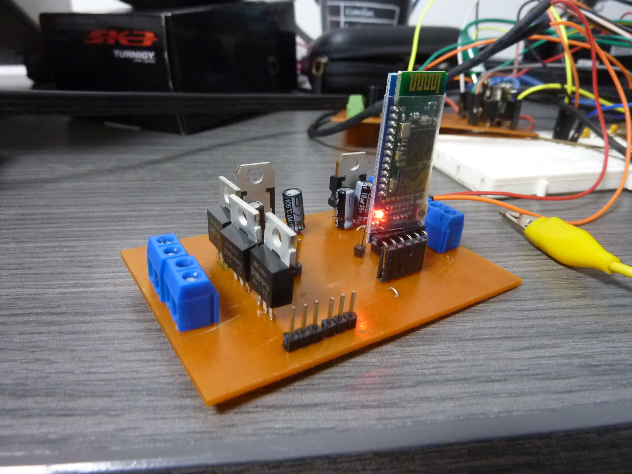
To protect my HM-10 module, I decided to make my voltage divider on a protoboard, but obviously I had not a 2K resistor so I used two 1K resistors in series. Once the voltage divider was exactly as I showed you in the previous step, it was ready to be connected to the board.

To connect the protoboard to my board, it is as easy as following the schematic of the voltage divider but based on my pinout. My pinout has the Tx connected to D3 and Rx connected to D2. Talking about connecting, it is important to mention that only now that I have my module, I understand how important are the two pins of the module that I didn't use which are the one that make a LED blink to understand the state of the Bluetooth connexion. The other one is a Pin to break a connexion to start a new one with another user, which is in reality very important. In a final product, this options will be integrated.

You have already see that schematic in week 12 because I made some corrections with the pinout of the motors, but this time I have to make some corrections with the Bluetooth part. But because nobody is perfect I made some mistakes... I added the voltage divider, but I just put a 2K resistor which is ok but those are extremely rare, and I had to search nearly everywhere in Lima, where SMDs components are rare, so imagine a 2K resistor. But after a while, I found some and I bought 20 to have a stock. I will now be able to connect my bluetooth module without problems.

This is the code to be able to change the speed of the BLDC motor and also to change the luminosity of LEDs, but in the final project, it will be RGB lights (so it will not change the luminosity, it will change the color), and for some reason, the luminosity of the white LEDs that I used at the beginning to test my board didn't change, the LEDs switch on and OFF but didn't shine more or less. Once again, as you can see I am using the Servo.h library to control my ESCs, but this time also the Blynk library, which will be the one that controls the HM-10 and gives you the capacity to use their development platform for Android and IOS. To know exactly which Blynk library to use depending of your connexion mode, you can use their example browser (in this case I used BlynkSimpleSerialBLE.h) which make the Bluetooth low energy connection, and also SoftwareSerial.h to create a SerialBle serial communication that the Blynk library will use to send and receive with the HM-10. Because it was interesting to know if the HM-10 was really able to receive and send data, I also added a velocity indicator which is actualise by the board with a map function. As you can see, with blynk if you want to read a value from the phone and translate it to an arduino variable, you have to use a Blynk_Write function and give it as an argument, the virtual Pin you are using (How to use Blynk - WEEK 15). In the function, you have to assign a variable where you will store the value sent by your phone and you will use param .asInt() or .asFloat() or asString(), depending of the kind of variable you are sending. To send a value to the phone, it is a bit different because you have to create a function (you will later know why) where you assign as arguments the virtual Pin where you want to send the information and the variable with the information you want to send.

In the void setup(), I define the baudrate of the SerialBLE connexion, use Blynk.begin to initialize the Blynk library and send it the Serial Connexion that I created in the pins of the HM-10 (2,3 - rx,tx), and finally the auth token which is unique and make su connexion secure only with authorized devices.
As I told you before, I will now explain you why you had to create a function to send data to the phone. In reality, the problem is that the microcontroller goes very fast, and the app Blynk can't manage the amount of data that you could send with it, so you have to say to the board, every how much time, you want to send the Value.
In my case I wrote 100 which represent 0,1 second. Finally in the void loop() I run the Blynk library and the timer library.
Download Code
")
This app is very simple, because I will make some upgrades to it next week, but basically I can increase the speed, see the speed with the gauge and change the bright of the LEDs with the green slider. You can also see a small bluetooth logo on the app, that is very useful to connect your phone to the HM-10, from the app, without having to go to the settings of the phone. Here tou can find a sketch to understand the structure of the connexion made when you use Blynk.

After soo many time waiting for my own professional custom PCBs, they arrived. The cost of 5 PCBs of the better quality, cost me 20$ because it was my first shop, otherwise it would cost me around 40$. The PCB, really is so different, much harder, it is much easier to solder on those type of PCB, they resist much more the heat, so you can be not that good soldering. This PCB, is in reality two layer, all the jumpers I made in the first one, have been in this case put at the other side of the board, so it looks so much better. The other nice detail that gives you this kind of PCB, is that you all you routing is protected by a none conductive silk screen that give you protection, more resistance and an incredible look because they even print you your logo. As you can notice, I put SMDs Mosfets and buy 6 of them on Arrow for 6$ and they arrived to lima en 3 days without any additional cost, and they give a much better look to the Board.

What I can say about the FabAcademy, is that it showed me how to solder. Now I am able to solder a 328p without much problem, as you can see the PCB looks very well, however, I have to confess that I would like to learn how to solder with solder paste. The problem of that, is that you also have to buy the layout of your PCB perforated in an aluminium sheet. I don't know how much it costs but if it will be a board that you are going to make often, it can accelerate the soldering process a lot.

Yes, I know! It looks simply awesome. The PCB, the SMD components, two black heat sinks, a good soldering process, and a lot of time invest gives me the result that I wanted. The bootloader just uploaded since the first try, however even if it doesn't like so, I fried two micro controllers. The reason, I had invert the 5V and 12V linear regulators. But don't worry, those are things that happens and now I know that I will never make this kind of mistakes again.
For this week group assignment, I had to send a message between two boards. As you all know I am the only one doing the FabAcademy in Utec this year, so I decided to use my two OLD Boards from electronics Design and Input, that was simply destroyed,
because I used them to understand better the serial interface because at the beginning it doesn't work, until I discovered that it only worked when I used the internal oscillator of 1 MHz. But by chance, I was still able to communicate with them, upload code, so with the help,
of my DIY programmer, a couple of cables and an FTDI, I have been able to send an integer from one board, to the other one, to switch one its built-in LED (this board had an if logic where if it read a 1, it had to switch on the LED and if it read a 0 it had to switch off the LED).
For like 30 minutes, I had problems and it didn't work until I discovered that it was because I was using .print (which is more to print things on your computer when using a Serial Communication),
instead of write which is more used when trying to communicate between one and another board. In this case, I am using 4 pins because I wanted to also send 5 volts to the board with the LED, have a GND connexion and obviously the two digital pins for the Serial communication.
Here you can find a sketch to understand better the connexions made for this group assignment.
Arduino Master Code
Arduino Slave Code
Controlling a BLDC and a LED Strip with an iPhone using Bluetooth 4.0 (BLE)
Please Contact Me For Any Collaborative Project