Final Project - TCG Card Reader
- Individual assignment: Describe your final project
Final Project
This assigment will explain steps take to develop my final project.
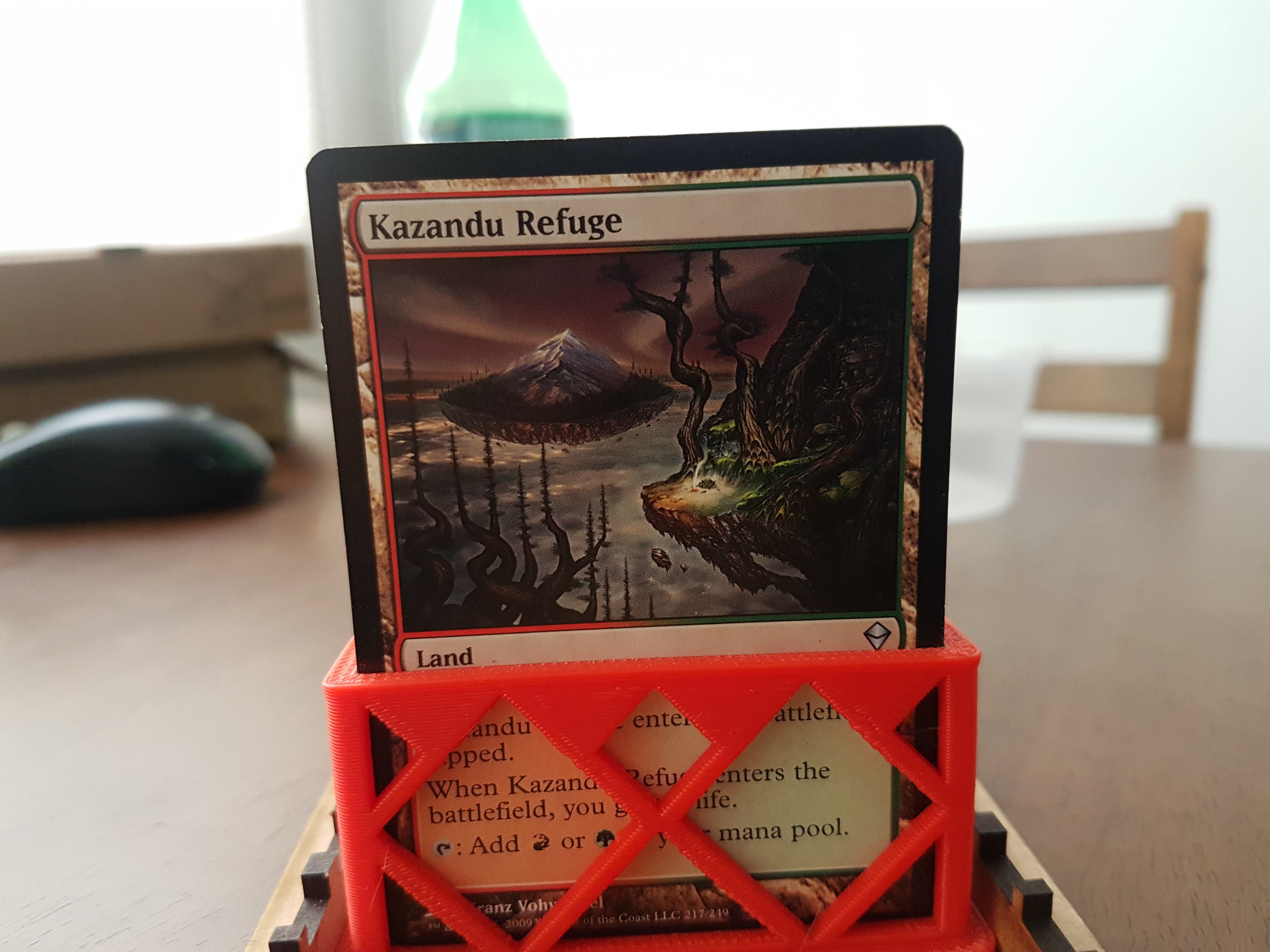
The project will be a TCG Card Reader. Using a Raspberry PI I will take pictures of a card using a webcam and process each image, to get card name and place it on a document. Cards used for this test will be Magic The Gathering cards
Schedule
| Part | Date | Description |
|---|---|---|
| Optical Recognition Test | June 10th-11th | Project 3D Design |
| 3D Design | June 12th-13th | Project Design |
| 3D Printing | June 14th | CAM Holder 3D Printing |
| Programming | June 14th | GUI Design |
| Laser Cut | June 15th | Housing |
| Electronics | June 16th | LED Board |
| Fixes and Debugging | June 16th-17th | Final revision |
| Presentation | 17th | Presentation with Neil |
Bill of Materials
| Part | Qty |
|---|---|
| Web CAM | 1 |
| Ethernet Cable | 1 |
| 5v/2.5A power for Raspberry | 1 |
| HDMI Cable | 1 |
| Raspberry Pi 3 | 1 |
| Wires | 5 |
| ABS Filament | Aprox 100gr |
| 3mm MDF | 0.5 m2 |
| Board Substrate | 0.2 m2 |
| LEDS | 4 |
| 499 Resistor | 4 |
| Solder | 20 cm 0.5 mm diameter |
Micro-Controller
The microcontroller used in this project is a Raspberry Pi with Raspbian OS.
Installation starts with downloading "NOOBS" (a package with several operating systems) and copying to the Raspberry. Once it starts must connected to internet to complete download.
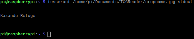
When installation of the operating systems finish, its time to donwload all package needed to use tesseract-OCR (Thats the character recognition software). But before that it's important to be sure we are working with Python 3.x. Using this command will do the trick.
With Python 3 as our main python version, I'm installing all libraries neccesary:
- Pillow
- pytesseract
- tesseract-OCR
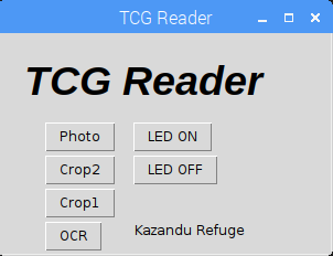
GUI
I made a program on the Raspberry. I used Tkinter to made the Graphic User Interface with the next operation:
- Photo: Take the photo
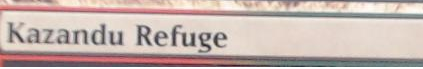
- Crop2: Crop at distance name 2
- Crop1: Crop at distante name 1
- Led ON/OFF: Turning leds on
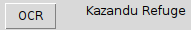
- OCR: Shows the captured name
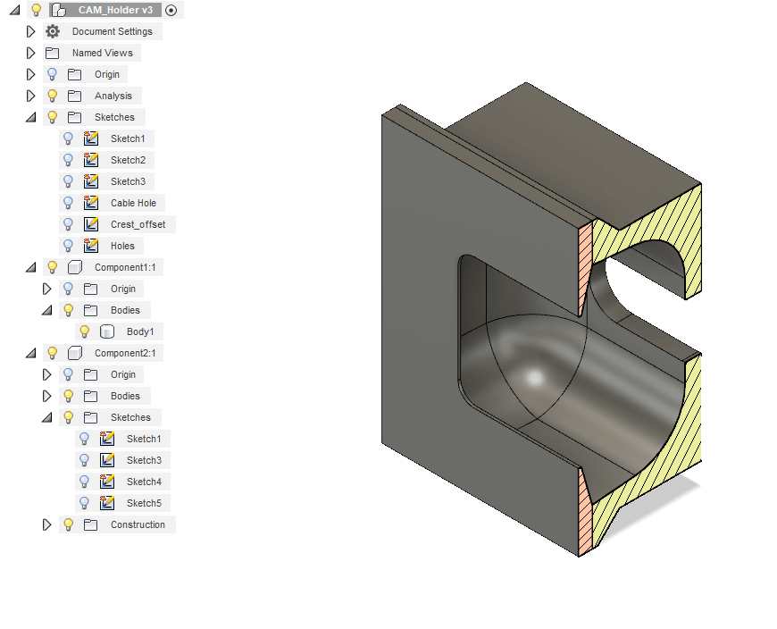
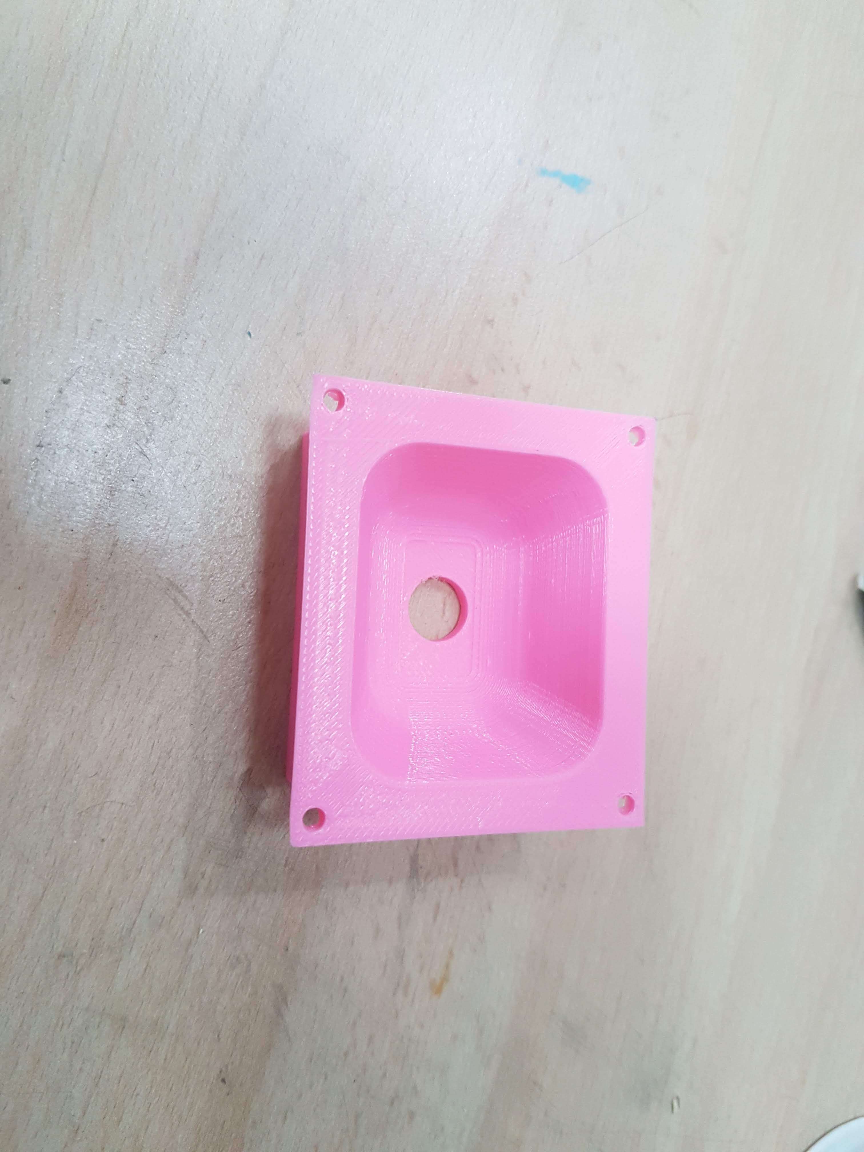
3D Print
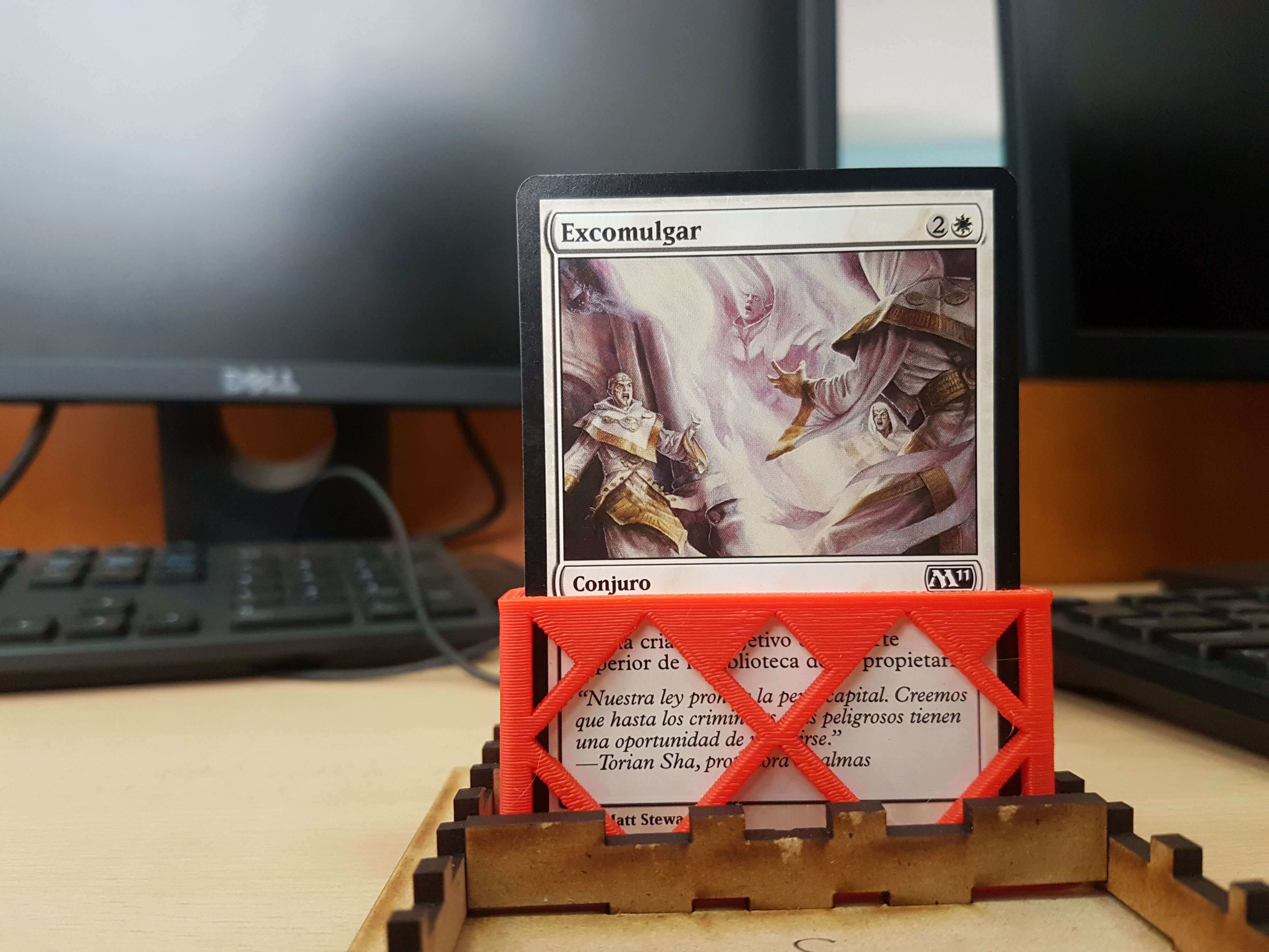
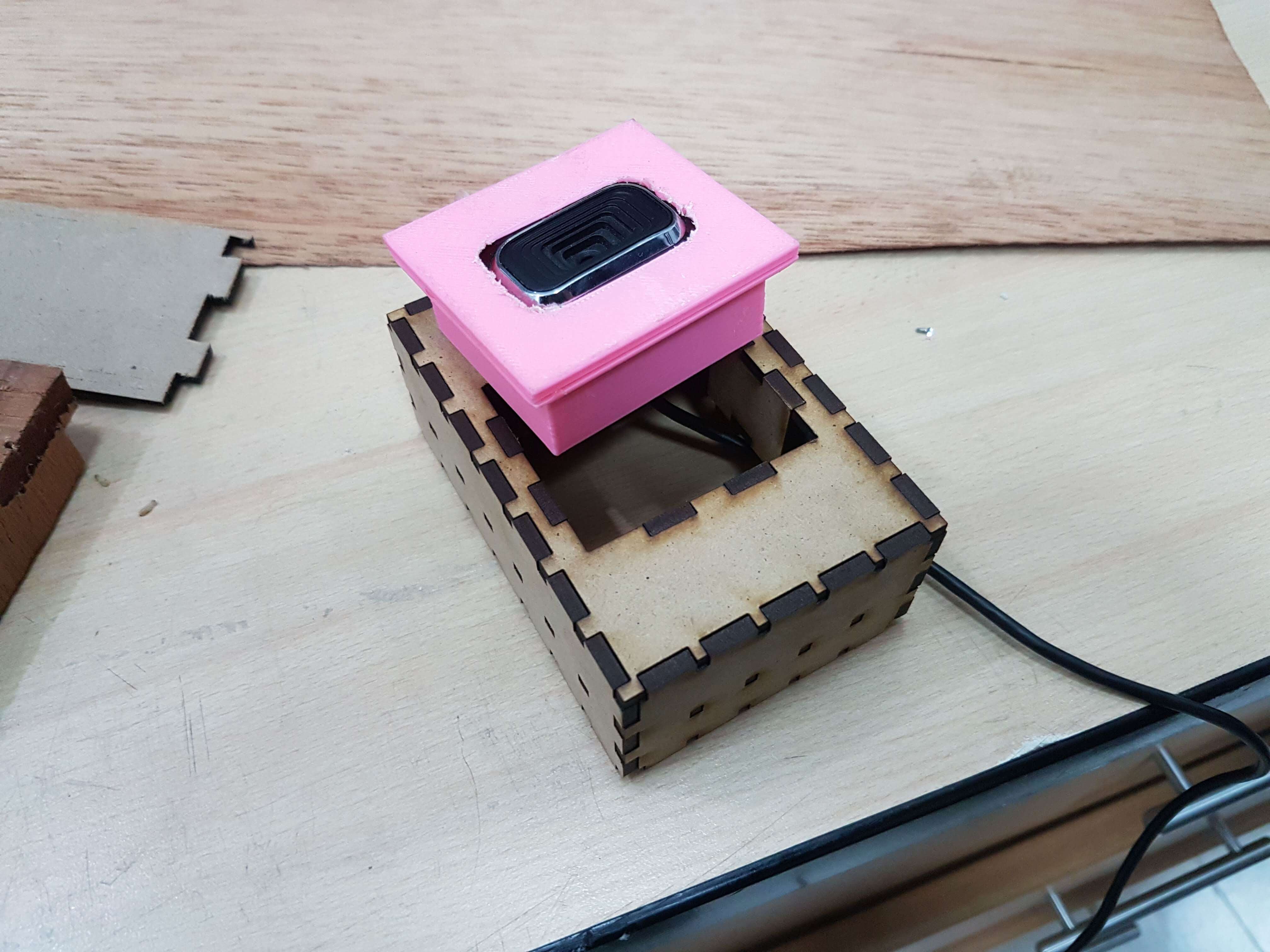
After completing Raspberry programming, I will 3d print a coupling to the camera for better fiting on the housing. Also I modeled a card holder to keep cards still when taking the photo.
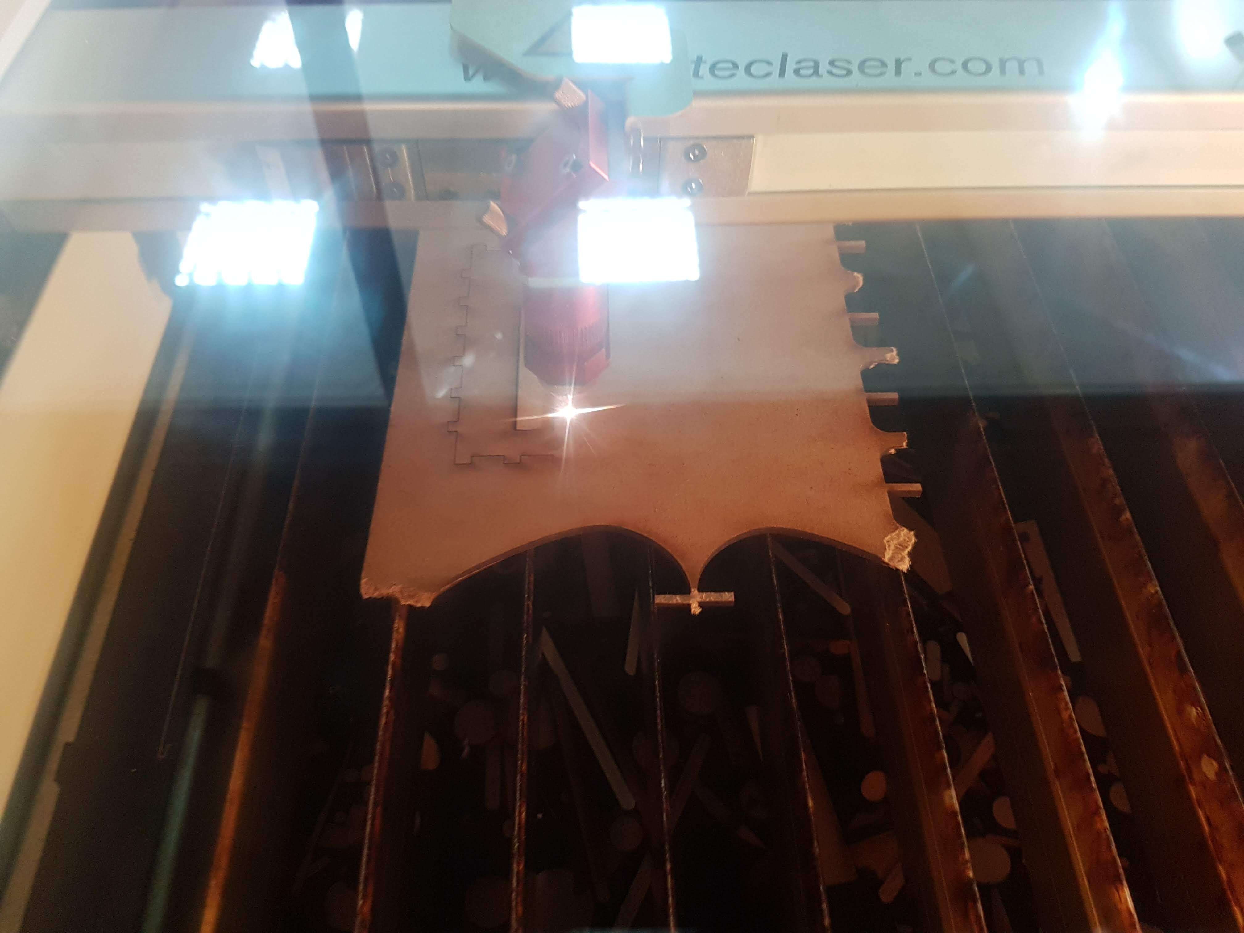
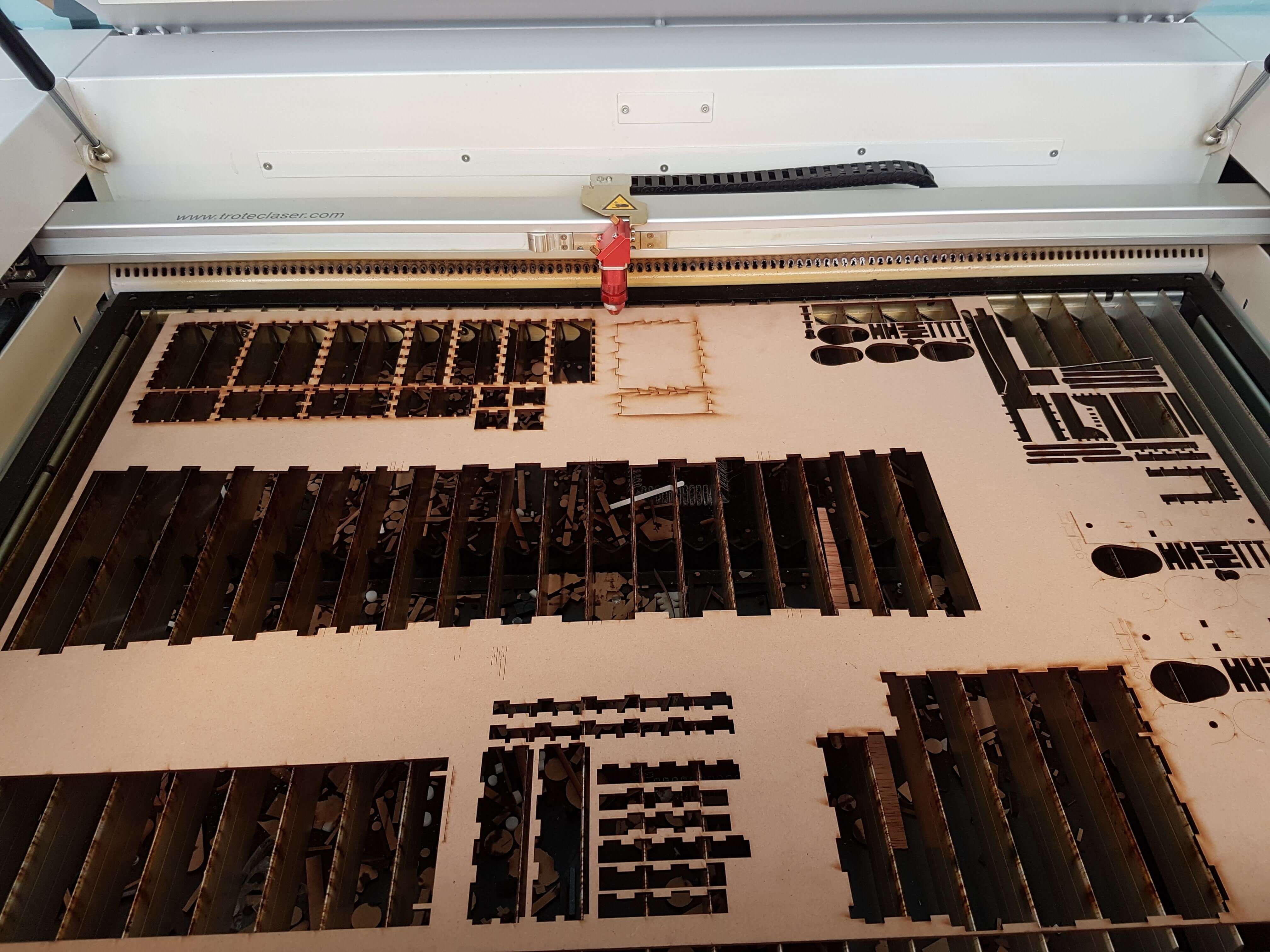
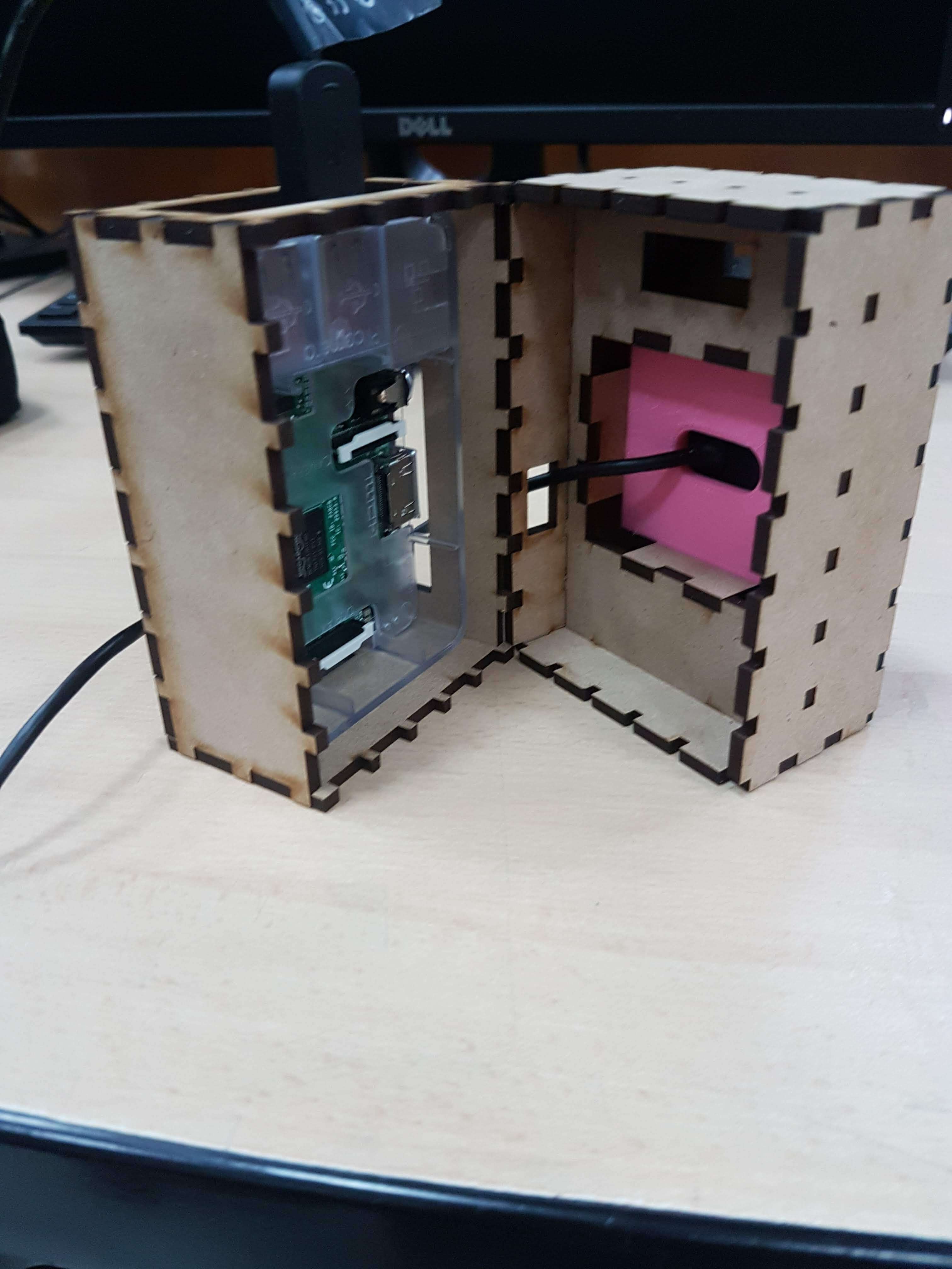
Laser cut
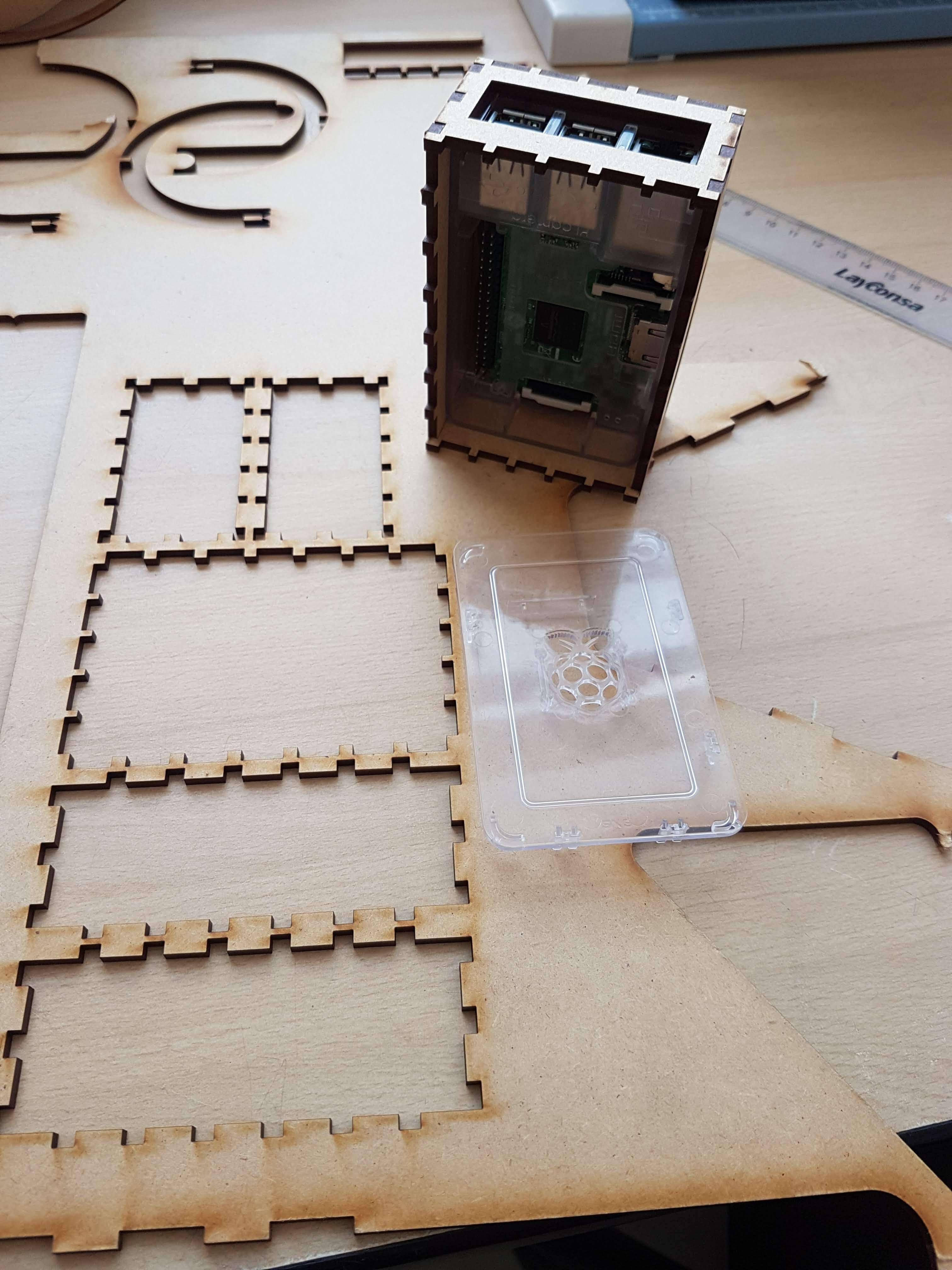
Once the programm its working in it's first iteration, the housing needs to be made. First half will hold the Raspberry and the other half will hold the camera and the lights.
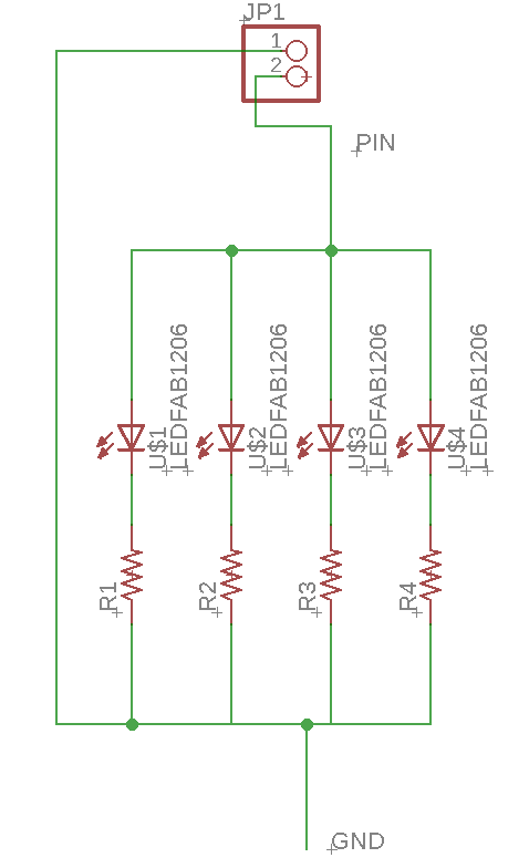
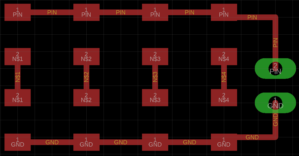
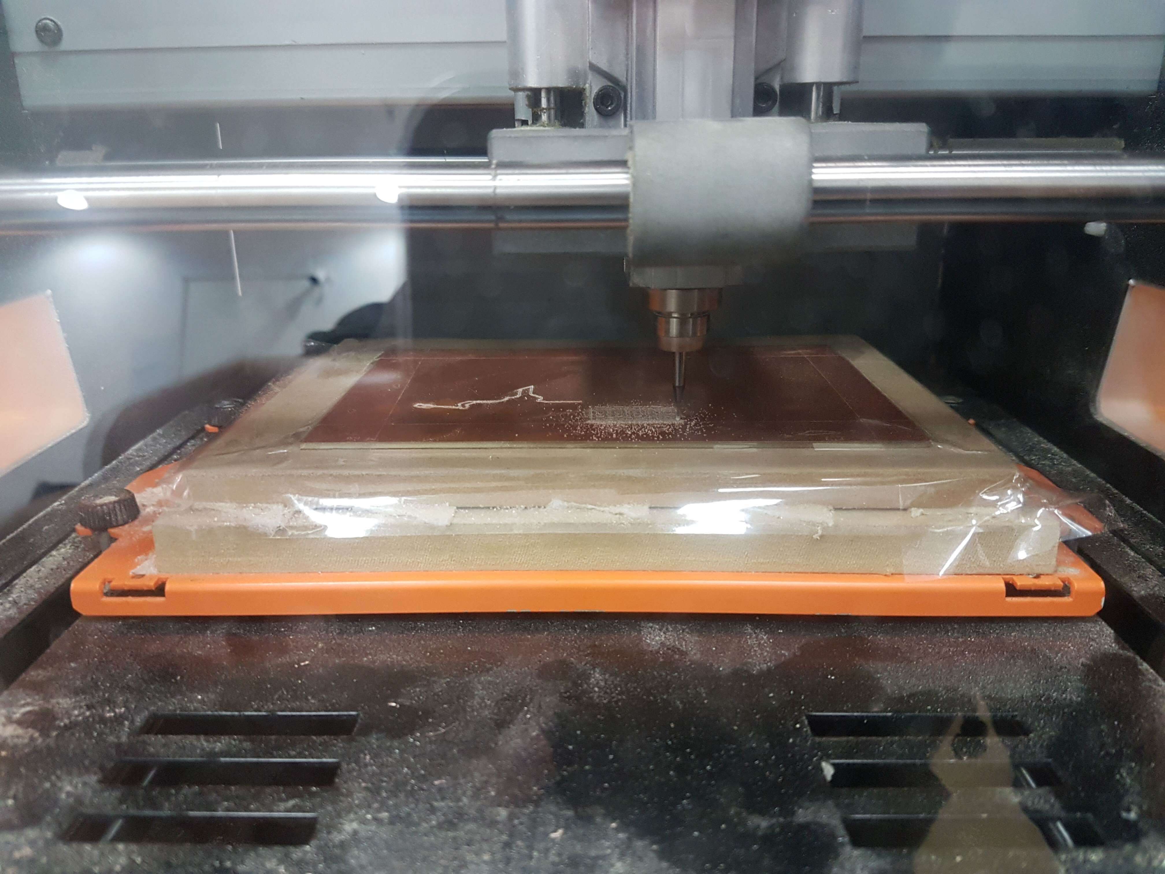
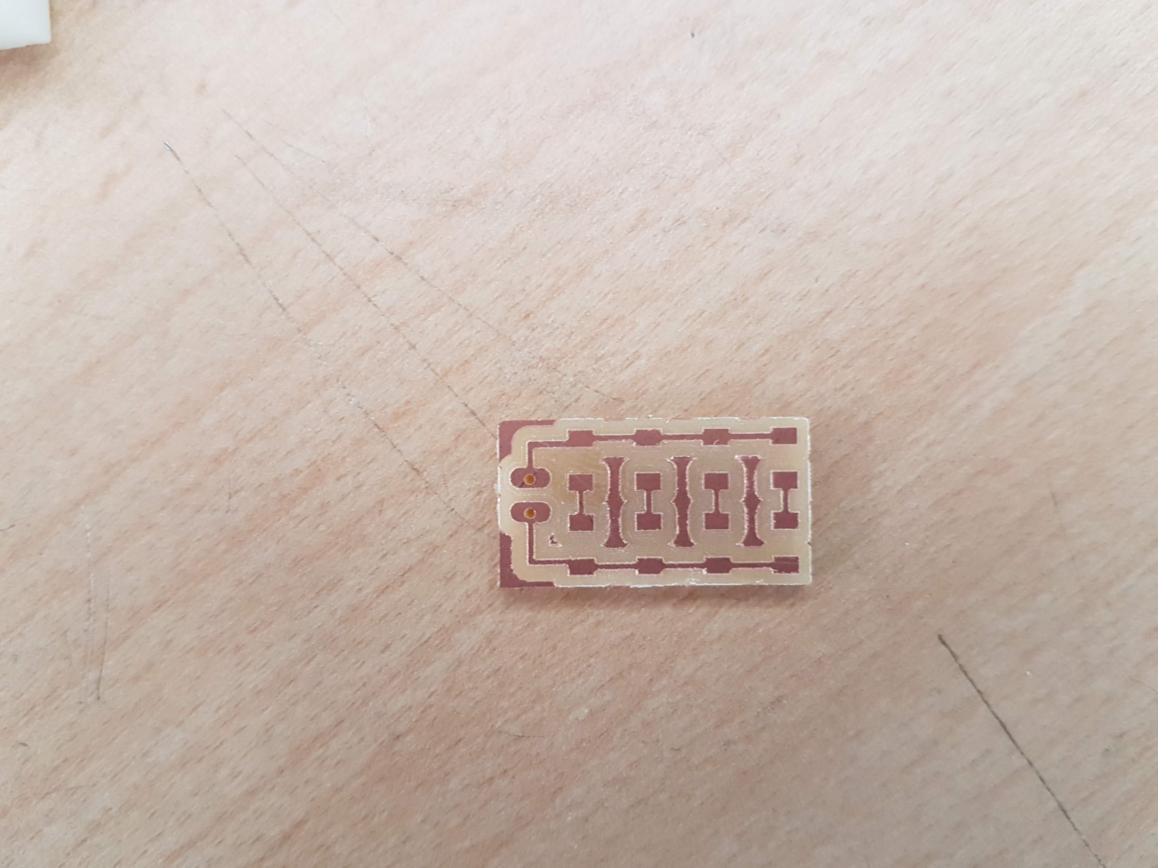
LED Board
A LED board will be connected to the Raspberry to provide extra lightning in case image might turn to dark.
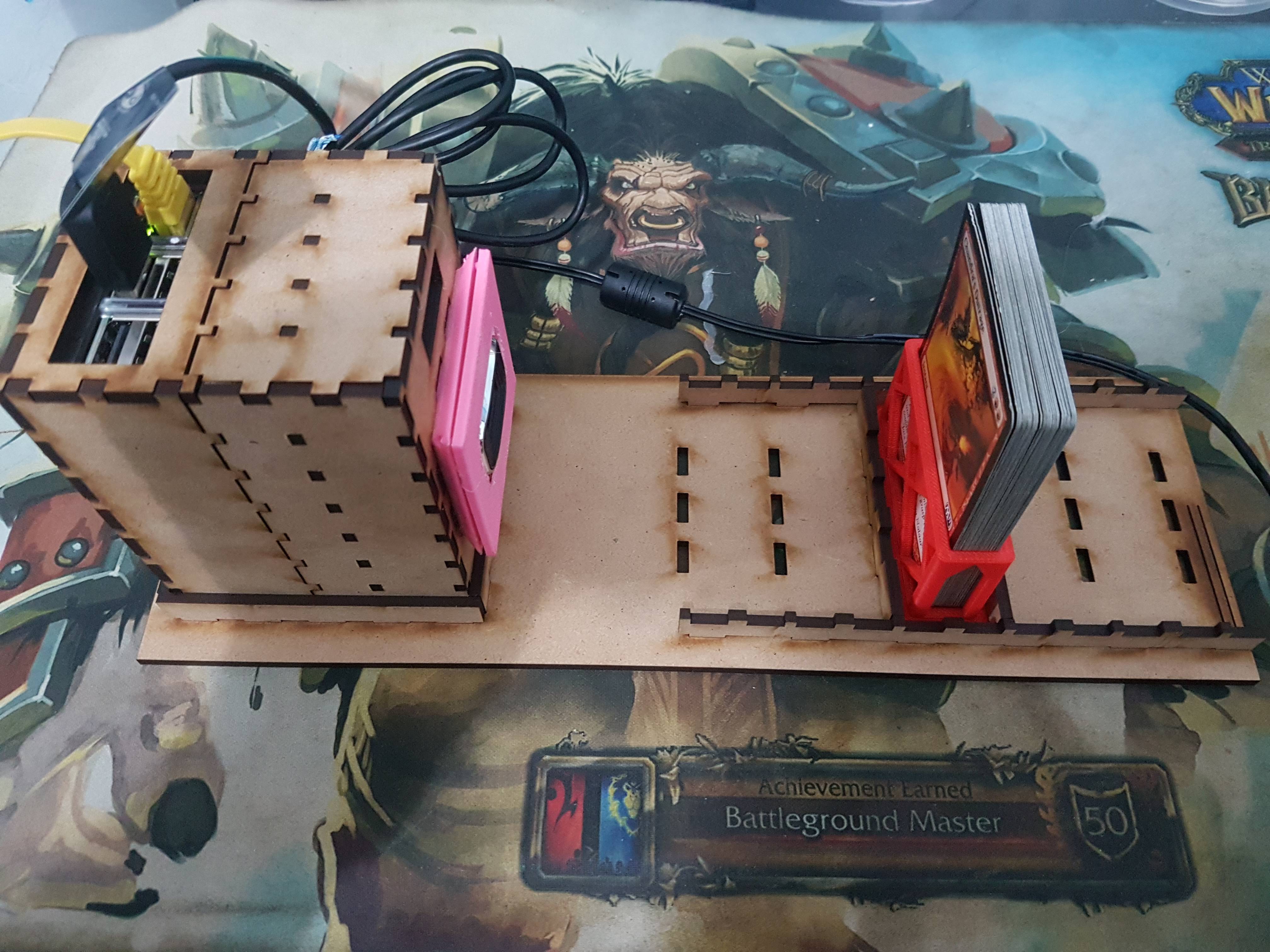
Putting everything together
Once all parts are made, we can out the proyect together.
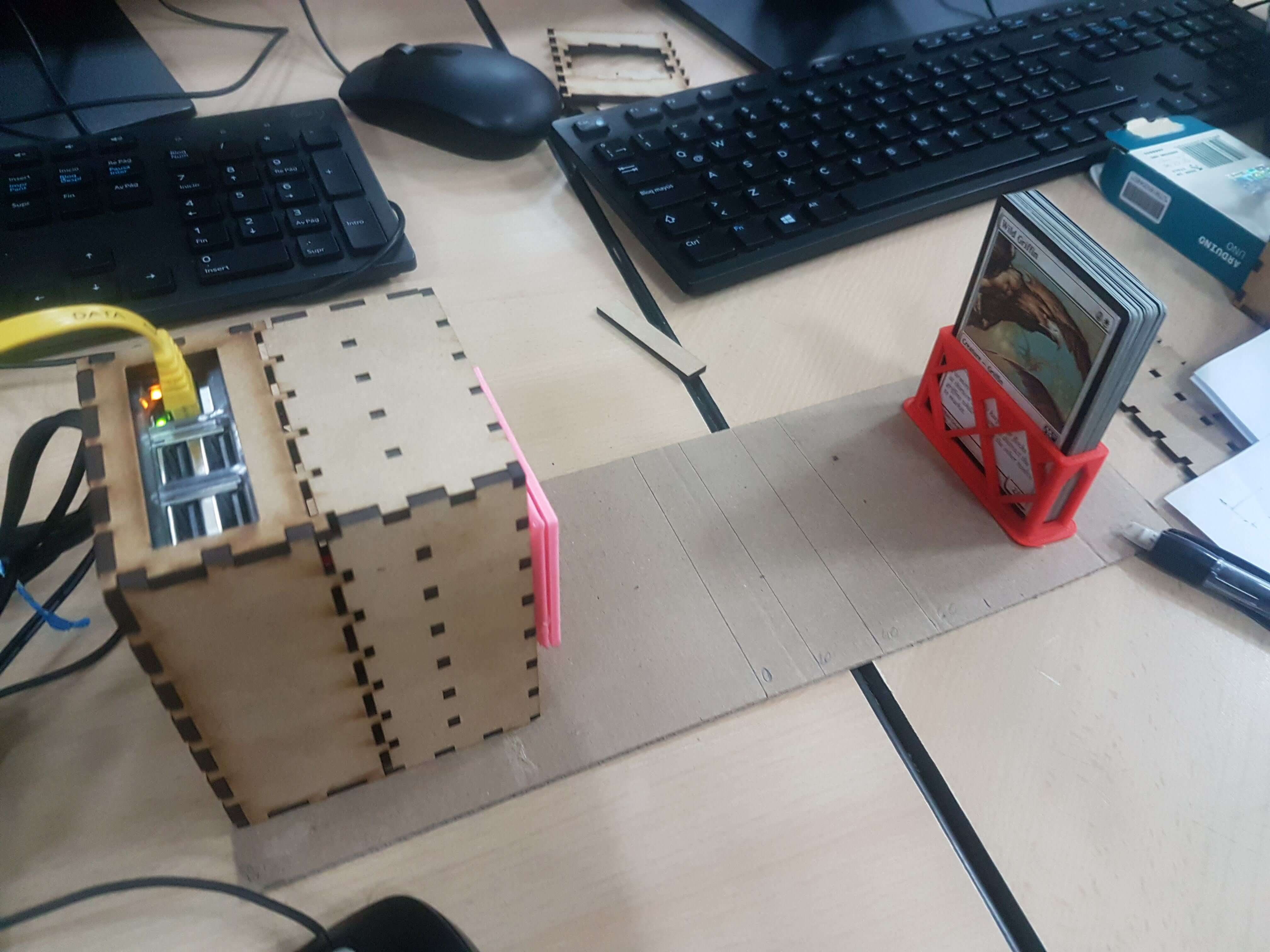
Testing
Once all parts are made, we can out the proyect together. I need to look out for a "perfect" spot between distance and resolution. Also light was important to get the correct name. With those testing in mind I made another piece to place the raspberry housing to a fixed position and to place the cards to several fixed positions.
With the new built some pictures were right but other throw some jiberrish. The OCR sometime could not detect the name because was too noise or blurry. Next will test a second camera.
Second camera
Using the camera we have here at the Fab Lab for each class, I tried to get a better quality photo. Lucky me its size was perfect to fit in the housing.
New Testing
With the new camera, the photos were better. It has a auto focus which helps to get better quality at close distances.
Using the new ccamera, I run the Python program and it works!