Week 9: Embedded programming
03/19/2019 - Stéphane Muller
The assignment for the week is to read a microcontroller data sheet and program our board to do something, with as many different programming languages and programming environments as possible. And as a group we have to compare the performance and development workflows for other architectures.
I thought this week would be easy for me since I already have some experience with the C language, web development and Arduino programming. Boy was I wrong... It turned out to be a lot more complicated than I anticipated.
Research
A LOT of research was necessary this week. I wanted to understand Neil's code for the echo board. As I said I already knew the C language, it's the first programming language I learned, but somehow I couldn't understand a single line in Neil's code. So first I thought, let's do this step by step and start by reading the datasheet. Maybe everything will get clearer then. Nope.
I'm not gonna lie, when I started reading the datasheet I got lost very quickly. I understood the hardware specifications, but once it came to registers and data models I got VERY confused. So I stopped and started reading tutorials instead. And it's only when I understood the programming part that I understood the content of the datasheet, because in the tutorials they kept refering to tables that were in the document.
Here is a list of the most useful resources I found:
- A great series of video tutorials on AVR programmming, very clear
- The website of the YouTube author, great stuff as well
- A series of articles on timers and interrupts
- A list of C operators
Planning and list of tasks
- Group assignment
- Blinking an LED Arduino style
- Blinking an LED C style
- Blinking an LED C style with interrupts
- Using a button C style with interrupts
- Using a button with double clicks C style
- Using a serial communication
Step by step
Group assignment
Here is a table comparing 4 different architectures:
| ATTiny45 | ATTiny84 | ATMega328 | ESP8266 | |
|---|---|---|---|---|
| Architecture | 8 bit AVR | 8 bit AVR | 8 bit AVR | 32 bit RISC |
| Voltage | 1.8-5.5V | 1.8-5.5V | 1.8-5.5V | 2.5-3.6V |
| Clock speed | 8MHz | 8MHz | 8MHz | 24-52MHz |
| Memory | 4Kb flash / 256b EEPROM / 256b SRAM | 8Kb flash / 512b EEPROM / 512b SRAM | 32Kb flash / 1Kb EEPROM / 2Kb SRAM | 64Kb RAM (instructions) / 96Kb RAM (data) |
| Pins | 2 analog / 6 digital / 2 PWM | 8 analog / 4 digital / 2 PWM | 6 analog / 14 digital / 6 PWM | 1 analog / 17 digital / 18 PWM |
| Language | Arduino / C | Arduino / C | Arduino / C | Arduino / C / C++ / JS / MicroPython / Go |
| Programmer | ISP | ISP | ISP / USART | UART |
All these characteristics are crucial in choosing the right architecture for your project. Analog sensors will require analog inputs for example. Depending on the application you might need more GPIO pins, etc.
Blinking an LED Arduino style
Okay, so let's start off easy with a simple blink program in Arduino.
#define LED 5

void setup() {
  pinMode(LED, OUTPUT);
}

void loop() {
  digitalWrite(LED, HIGH);
  delay(1000);
  digitalWrite(LED, LOW);
  delay(1000);
}
First you have the setup() where you specify the pins you're going to use and wether they're going to be inputs or outputs. And then there's the infinite loop where you put your code. Here we just tell the MCU to apply a HIGH voltage, delay 1000ms, then apply a LOW voltage and pause 1000ms again. No biggy, nothing fancy.
Then I wanted to read the button's state and turn on the LED, but the right way to do that would be to use event management and interrupts. There's a library you can use in Arduino but it only works with Arduinos and not our ATTiny. So I decided to move on to plain C already and that's where things got interesting.
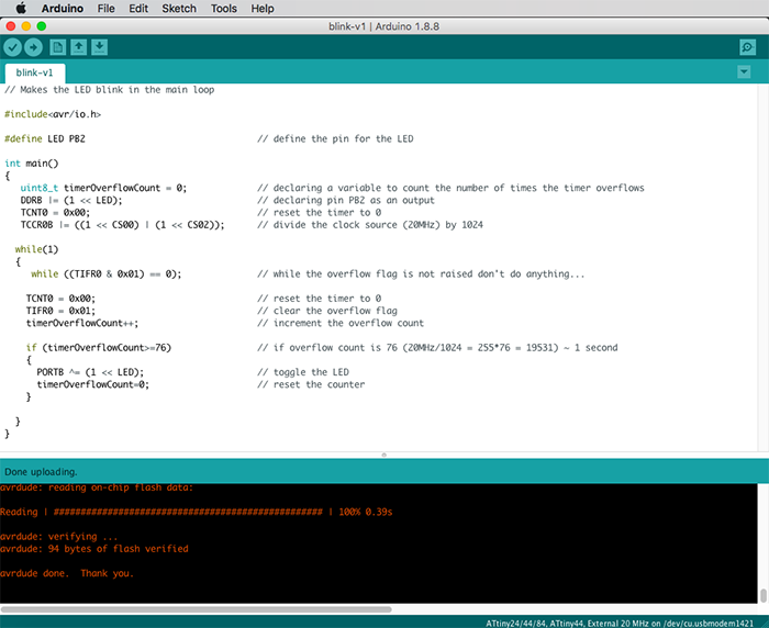
Blinking an LED C style
Let's redo our simple blinking program first. It's the Hello World of electronics I suppose.
// Makes the LED blink in the main loop

#include <avr/io.h>

#define LED PB2                                // define the pin for the LED

int main()
{
   uint8_t timerOverflowCount = 0;             // declaring a variable to count the number of times the timer overflows
   DDRB |= (1 << LED);                         // declaring pin PB2 as an output
   TCNT0 = 0x00;                               // reset the timer to 0
   TCCR0B |= ((1 << CS00) | (1 << CS02));      // divide the clock source (20MHz) by 1024

  while(1)
  {
    while ((TIFR0 & 0x01) == 0);               // while the overflow flag is not raised don't do anything...

    TCNT0 = 0x00;                          		 // reset the timer to 0
    TIFR0 = 0x01;                          		 // clear the overflow flag
    timerOverflowCount++;                  		 // increment the overflow count

    if (timerOverflowCount>=76)            		 // if overflow count is 76 (20MHz/1024 = 255*76 = 19531) ~ 1 second
    {
      PORTB ^= (1 << LED);                 		 // toggle the LED
      timerOverflowCount=0;               		 // reset the counter
    }
  }
}
A lot of new things here... To start understanding this code, first I needed to understand what the hell was going on with these instructions: DDRB |= (1 << LED). Here comes bit masking, bit shifting and logic operators.
Alright, so on the right we're doing what is called bit shifting. Basically we're shifting a 1 to the position defined by the constant LED (LED = PB2 = 2).
Then on the left we have a byte (which is 8 bits) called DDRB and we're doing an OR to it with the bit we shifted on the right. That gives us the following:
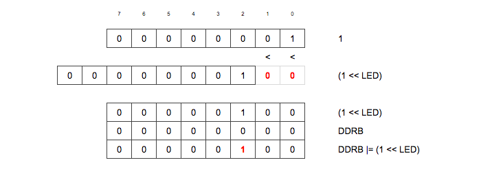
But why do we do that, you may ask? Well, that's the second important thing to learn here. Using a microcontroller involves playing with virtual data registers that control its behavior. Data registers are bytes and each bit or combination of bits controls something in particular.
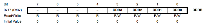
Here for example, the DDRB byte is the Port B Data Direction Register. It specifies the direction of the data flow (input or output) for the group of pins in port B. By default the bits are set to 0 (so inputs) and by setting these bits to 1 we tell the MCU we want outputs.
Instead of using delays, here we're using one of the internal timers of the MCU. There are 3 timers in the ATTiny44, 2 one byte timers and 1 two bytes timer. Here we're using timer 0, which is 1 byte long (so 8 bits). That means it can count up to 255, then it resets and starts again.
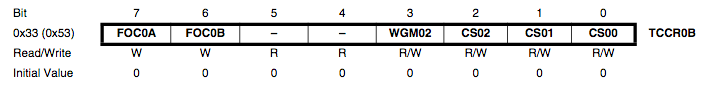
With our 20MHz clock, it's very very fast. So what we're going to do is divide the clock source by 1024. That is done by setting 2 bits to one in the TCCR0B byte. Their combination tells the MCU to divide the clock by 1024.
TCCR0B |= ((1 << CS00) | (1 << CS02));And that we know thanks to the datasheet:
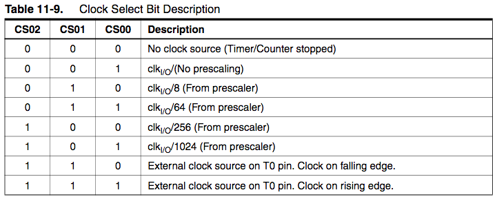
We divided the clock by 1024, which means the timer is now incremented every 51µs and it finishes counting to 255 (it overflows) every 13ms. So to get a 1 second delay we need to count 76 timer overflows.
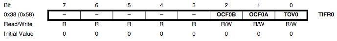
When the timer overflows, it raises a flag. This flag is called TOV0 and is contained in the Timer/Counter 0 Interrupt Flag Register: TIFR0. So whenever the timer overflows, this bit is set to 1. So in the code we're checking when this flag is raised and when it is, we reset the timer and the flag and we increment the overflow count.
And finally, when we get to 76, we toggle the LED by setting the corresponding bit in the Port B data register. Here we use a XOR operator, which means that whatever the previous state it will set it to the opposite one.
PORTB ^= (1 << LED);Blinking an LED C style with interrupts
To slowly start using interrupts, let's try using a timer interrupt to blink the light.
// Makes the LED blink using time interrupts
#include <avr/io.h>
#include <avr/interrupt.h>
#define LED PB2 // define the pin for the LED
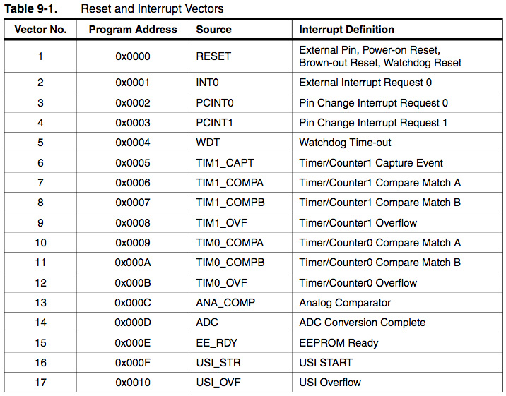
ISR(TIM1_OVF_vect) // define the Interrupt Service Routine (ISR) for when timer 1 overflows
{
PORTB ^= (1 << LED); // toggle the LED
TCNT1 = 46004; // 16 bit counter so 65535 values, start timer at 46004 (65535 - 20MHz/1024)
}
int main()
{
DDRB |= (1 << LED); // declaring pin PB2 as an output
TCNT1 = 46004; // 16 bit counter so 65535 values, start timer 1 at 46004 (65535 - 20MHz/1024)
TCCR1A = 0x00; // clear register A for the timer
TCCR1B = (1<<CS10) | (1<<CS12); // divide the clock source (20MHz) by 1024
TIMSK1 = (1 << TOIE1); // enable timer 1 overflow interrupt (TOIE1)
sei(); // enable global interrupts by setting global interrupt enable bit in SREG
while(1)
{
// infinite loop to put any code
}
}This time we'll be using timer 1, which is a 16 bit counter. That way we won't have to count the number of overflows, we can just start the timer at a certain value and wait until it overflows to raise an interrupt.
The maximum number the timer can count to is 65535 and after we divided the clock by 1024, the timer needs to count 19531 to one second. So if we set the timer to 65535-19531 = 46004, when it gets to 65535, one second will have passed.
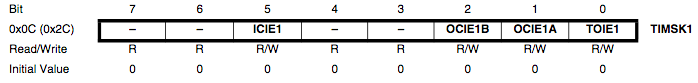
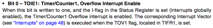
What's new here is that we need to enable the interrupt (bit TOIE1) for timer 1 in the Timer/Counter Interrupt Mask Register 1.
And then we enable global interrupts with sei();. This means that the main code will execute normally and whenever the timer overflows, the main code will be interrupted and a specific routine will be executed instead, before returning to the main code and picking up exactly where it left off.
The routine here toggles the LED and resets the timer.
ISR(TIM1_OVF_vect)
{
  PORTB ^= (1 << LED);
  TCNT1 = 46004;
}
Using a button C style with interrupts
Now let's use a button to start/stop the blinking! We'll reuse the previous code and add the handling of the button.
// Here the button toggles the blinking LED on or off
#include <avr/io.h>
#include <avr/interrupt.h>
#define LED PB2 // define the pin for the LED
volatile uint8_t pinStateChange = 0; // declaring global variable to be able to access it in routines
ISR(PCINT0_vect) // define the Interrupt Service Routine (ISR) for when the button pin changes state
{
if(pinStateChange == 1) // if the button has been pressed do...
{
TIMSK1 ^= (1 << TOIE1); // launch the timer and start blinking the LED
}
pinStateChange ^= 1; // the button has been toggled
}
ISR(TIM1_OVF_vect) // define the Interrupt Service Routine (ISR) for when timer 1 overflows
{
PORTB ^= (1 << LED); // toggle the LED
TCNT1 = 46004; // 16 bit counter so 65536 values, start timer at 46004 (65535 - 20MHz/1024)
}
int main()
{
DDRB |= (1 << LED); // declaring pin PB2 as an output
PCMSK0 |= (1 << PCINT7); // enable pin PA7 (aka PCINT7) for interrupts
GIMSK |= (1 << PCIE0); // enable interrupts for this group of pins
TCNT1 = 46004; // 16 bit counter so 65536 values, start timer 1 at 46004 (65535 - 20MHz/1024)
TCCR1A = 0x00; // clear register A for the timer
TCCR1B = (1<<CS10) | (1<<CS12); // divide the clock source (20MHz) by 1024
sei();
while(1)
{
// infinite loop to put any code
}
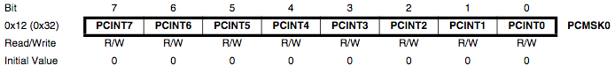
}Not that much more complicated really. We just added a new interrupt, one that is raised whenever a pin changes state. To do that, we just had to enable the pin connected to the button in the Pin Change Mask Register and enable interrupts for the right group of pins in the General Interrupt Mask Register.
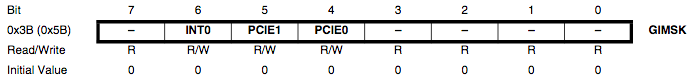
Then we find the right interrupt vector and launch the routine to start the blinking.
When you click on the button, the pin changes state twice: on press AND on release. We need to take that into account, otherwise the routine is executed twice.
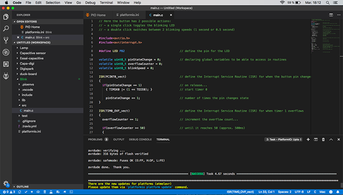
Using a button with double clicks C style
Because I like challenges and I got excited with blinking my LED in plain C, I thought it would be interesting to add another feature to that button and try to implement a double click! Each time you double click on the button, the blinking will change speed.
// Here the button has 2 possible actions:
// - a single click toggles the blinking LED
// - a double click switches between 2 blinking speeds (1 second or 0.5 second)

#include <avr/io.h>
#include <avr/interrupt.h>

#define LED PB2                                // define the pin for the LED

volatile uint8_t pinStateChange = 0;           // declaring global variables to be able to access in routines
volatile uint8_t overflowCounter = 0;
volatile uint8_t blinkSpeed = 0;

ISR(PCINT0_vect)                               // define the Interrupt Service Routine (ISR) for when the button pin changes state
{
  if(pinStateChange == 1)                      // on release...
    { TIMSK0 |= (1 << TOIE0); }                // start timer 0

    pinStateChange += 1;                       // number of times the pin changes state
}

ISR(TIM0_OVF_vect)                             // define the Interrupt Service Routine (ISR) for when timer 1 overflows
{
  overflowCounter += 1;                        // increment the overflow count...

  if(overflowCounter >= 50)                    // until it reaches 50 (approx. 500ms)
  {
    if(pinStateChange == 2)                    // if the button has been pushed once...
    { TIMSK1 ^= (1 << TOIE1); }                // toggle timer for blinking LED

    if(pinStateChange == 4)                    // if the button has been push twice in less than 500ms...
    { blinkSpeed ^= 1; }                       // toggle blinking speed

    pinStateChange = 0;                        // reset variable
    overflowCounter = 0;                       // reset counter
    TIMSK0 &= (0 << TOIE0);                    // disable timer 0
  }
}

ISR(TIM1_OVF_vect)                             // define the Interrupt Service Routine (ISR) for when timer 1 overflows
{
  PORTB ^= (1 << LED);                         // toggle the LED

  if(blinkSpeed == 0)
  { TCNT1 = 46004; }                           // blink once every second

  if(blinkSpeed == 1)
  { TCNT1 = 56004; }                           // blink twice every second
}

int main()
{
  DDRB |= (1 << LED);                          // declaring pin PB2 as an output

  PCMSK0 |= (1 << PCINT7);                     // enable pin PA7 (aka PCINT7) for interrupts
  GIMSK |= (1 << PCIE0);                       // enable interrupts for this group of pins

  TCNT1 = 46004;                               // 16 bit counter so 65536 values, start timer 1 at 46004 (65535 - 20MHz/1024)
  TCCR1A = 0x00;                               // clear register A for the timer
  TCCR1B = (1<<CS10) | (1<<CS12);              // divide the clock source (20MHz) by 1024

  TCNT0 = 0;                                   // reset the timer to 0
  TCCR0A = 0x00;
  TCCR0B = (1 << CS10) | (1 << CS12);          // divide the clock source (20MHz) by 1024

  sei();

  while(1)
  {
                                               // infinite loop to put any code
  }
}
I started out with my previous program and added to it. To achieve the double click feature I used a second timer which started counting at the first click. The timer counts for approximately 500ms and if there is a second click it toggles the blinking speed and if not it just toggles the blinking.
Using a serial communication
Because serial communication is very useful for debugging, I really wanted to implement it in my program. Neil's code in the echo program seemed awfully complicated so I thought maybe I could use an existing library. I found several, but none worked with the ATTiny44.

So as a workaround I just reused Neil's code!
// Here the button has 2 possible actions:
// - a single click toggles the blinking LED
// - a double click switches between 2 blinking speeds (1 second or 0.5 second)

#include <avr/io.h>
#include <avr/interrupt.h>

#include "uart.h"

// ********************************************************************************************************* //
// ********************************** Neil's code from hello.ftdi.44.echo.c ******************************** //

#include <util/delay.h>
#include <avr/pgmspace.h>

#define output(directions,pin) (directions |= pin) // set port direction for output
#define set(port,pin) (port |= pin) // set port pin
#define clear(port,pin) (port &= (~pin)) // clear port pin
#define pin_test(pins,pin) (pins & pin) // test for port pin
#define bit_test(byte,bit) (byte & (1 << bit)) // test for bit set
#define bit_delay_time 8.5 // bit delay for 115200 with overhead
#define bit_delay() _delay_us(bit_delay_time) // RS232 bit delay
#define half_bit_delay() _delay_us(bit_delay_time/2) // RS232 half bit delay
#define char_delay() _delay_ms(10) // char delay

#define serial_port PORTA
#define serial_direction DDRA
#define serial_pins PINA
#define serial_pin_in (1 << PA0)
#define serial_pin_out (1 << PA1)

#define max_buffer 25

void get_char(volatile unsigned char *pins, unsigned char pin, char *rxbyte) {
   //
   // read character into rxbyte on pins pin
   //    assumes line driver (inverts bits)
   //
   *rxbyte = 0;
   while (pin_test(*pins,pin))
      //
      // wait for start bit
      //
      ;
   //
   // delay to middle of first data bit
   //
   half_bit_delay();
   bit_delay();
   //
   // unrolled loop to read data bits
   //
   if pin_test(*pins,pin)
      *rxbyte |= (1 << 0);
   else
      *rxbyte |= (0 << 0);
   bit_delay();
   if pin_test(*pins,pin)
      *rxbyte |= (1 << 1);
   else
      *rxbyte |= (0 << 1);
   bit_delay();
   if pin_test(*pins,pin)
      *rxbyte |= (1 << 2);
   else
      *rxbyte |= (0 << 2);
   bit_delay();
   if pin_test(*pins,pin)
      *rxbyte |= (1 << 3);
   else
      *rxbyte |= (0 << 3);
   bit_delay();
   if pin_test(*pins,pin)
      *rxbyte |= (1 << 4);
   else
      *rxbyte |= (0 << 4);
   bit_delay();
   if pin_test(*pins,pin)
      *rxbyte |= (1 << 5);
   else
      *rxbyte |= (0 << 5);
   bit_delay();
   if pin_test(*pins,pin)
      *rxbyte |= (1 << 6);
   else
      *rxbyte |= (0 << 6);
   bit_delay();
   if pin_test(*pins,pin)
      *rxbyte |= (1 << 7);
   else
      *rxbyte |= (0 << 7);
   //
   // wait for stop bit
   //
   bit_delay();
   half_bit_delay();
   }

void put_char(volatile unsigned char *port, unsigned char pin, char txchar) {
   //
   // send character in txchar on port pin
   //    assumes line driver (inverts bits)
   //
   // start bit
   //
   clear(*port,pin);
   bit_delay();
   //
   // unrolled loop to write data bits
   //
   if bit_test(txchar,0)
      set(*port,pin);
   else
      clear(*port,pin);
   bit_delay();
   if bit_test(txchar,1)
      set(*port,pin);
   else
      clear(*port,pin);
   bit_delay();
   if bit_test(txchar,2)
      set(*port,pin);
   else
      clear(*port,pin);
   bit_delay();
   if bit_test(txchar,3)
      set(*port,pin);
   else
      clear(*port,pin);
   bit_delay();
   if bit_test(txchar,4)
      set(*port,pin);
   else
      clear(*port,pin);
   bit_delay();
   if bit_test(txchar,5)
      set(*port,pin);
   else
      clear(*port,pin);
   bit_delay();
   if bit_test(txchar,6)
      set(*port,pin);
   else
      clear(*port,pin);
   bit_delay();
   if bit_test(txchar,7)
      set(*port,pin);
   else
      clear(*port,pin);
   bit_delay();
   //
   // stop bit
   //
   set(*port,pin);
   bit_delay();
   //
   // char delay
   //
   bit_delay();
   }

void put_string(volatile unsigned char *port, unsigned char pin, char *str) {
   //
   // print a null-terminated string
   //
   static int index;
   index = 0;
   do {
      put_char(port, pin, str[index]);
      ++index;
      } while (str[index] != 0);
   }

// ********************************** End ****************************************************************** //
// ********************************************************************************************************* //

#define LED PB2                                // define the pin for the LED

volatile uint8_t pinStateChange = 9;           // declaring global variables to be able to access in routines
volatile uint8_t overflowCounter = 0;
volatile uint8_t blinkSpeed = 0;

ISR(PCINT0_vect)                               // define the Interrupt Service Routine (ISR) for when the button pin changes state
{
  if(pinStateChange == 9)                      // on release...
  {
    welcomeMsg();
    pinStateChange = 0;
  }

  if(pinStateChange == 1)                      // on release...
  { TIMSK0 |= (1 << TOIE0); }                  // start timer 0

  pinStateChange += 1;                         // number of times the pin changes state
}

ISR(TIM0_OVF_vect)                             // define the Interrupt Service Routine (ISR) for when timer 1 overflows
{
  overflowCounter += 1;                        // increment the overflow count...

  if(overflowCounter >= 50)                    // until it reaches 50 (approx. 500ms)
  {
    if(pinStateChange == 2)                    // if the button has been pushed once...
    { TIMSK1 ^= (1 << TOIE1); }                // toggle timer for blinking LED

    if(pinStateChange == 4)                    // if the button has been push twice in less than 500ms...
    { blinkSpeed ^= 1; }                       // toggle blinking speed

    pinStateChange = 0;                        // reset variable
    overflowCounter = 0;                       // reset counter
    TIMSK0 &= (0 << TOIE0);                    // disable timer 0
  }
}

ISR(TIM1_OVF_vect)                             // define the Interrupt Service Routine (ISR) for when timer 1 overflows
{
  PORTB ^= (1 << LED);                         // toggle the LED

  if(blinkSpeed == 0)
  { TCNT1 = 46004; }                           // blink once every second

  if(blinkSpeed == 1)
  { TCNT1 = 56004; }                           // blink twice every second
}

void startBlink(void)
{
  TIMSK1 |= (1 << TOIE1);

  put_string(&serial_port, serial_pin_out, "LED is now blinking!");
  put_char(&serial_port, serial_pin_out, 10);
  put_string(&serial_port, serial_pin_out, ">> ");
}

void stopBlink(void)
{
  TIMSK1 &= (0 << TOIE1);
  PORTB &= (0 << LED);

  put_string(&serial_port, serial_pin_out, "LED is now off!");
  put_char(&serial_port, serial_pin_out, 10);
  put_string(&serial_port, serial_pin_out, ">> ");
}

void onLED(void)
{
  TIMSK1 &= (0 << TOIE1);
  PORTB |= (1 << LED);

  put_string(&serial_port, serial_pin_out, "LED is now on!");
  put_char(&serial_port, serial_pin_out, 10);
  put_string(&serial_port, serial_pin_out, ">> ");
}

void welcomeMsg(void)
{
  put_string(&serial_port, serial_pin_out, "Welcome to Blinky 2019!");
  put_char(&serial_port, serial_pin_out, 10);
  put_string(&serial_port, serial_pin_out, "To make the LED blink, type \"b\", to turn on the LED, type \"s\", to turn off the LED, type \"o\". What's it gonna be? ");
  put_char(&serial_port, serial_pin_out, 10);
  put_string(&serial_port, serial_pin_out, ">> ");
}

int main()
{
  static char chr;
  static char buffer[max_buffer] = {0};
  static int index = 1;

  CLKPR = (1 << CLKPCE);
  CLKPR = (0 << CLKPS3) | (0 << CLKPS2) | (0 << CLKPS1) | (0 << CLKPS0);

  set(serial_port, serial_pin_out);
  output(serial_direction, serial_pin_out);

  DDRB |= (1 << LED);                          // declaring pin PB2 as an output

  PCMSK0 |= (1 << PCINT7);                     // enable pin PA7 (aka PCINT7) for interrupts
  GIMSK |= (1 << PCIE0);                       // enable interrupts for this group of pins

  TCNT1 = 46004;                               // 16 bit counter so 65536 values, start timer 1 at 46004 (65535 - 20MHz/1024)
  TCCR1A = 0x00;                               // clear register A for the timer
  TCCR1B = (1<<CS10) | (1<<CS12);              // divide the clock source (20MHz) by 1024

  TCNT0 = 0;                                   // reset the timer to 0
  TCCR0A = 0x00;
  TCCR0B = (1 << CS10) | (1 << CS12);          // divide the clock source (20MHz) by 1024

  welcomeMsg();

  sei();

  while(1)
  {
    get_char(&serial_pins, serial_pin_in, &chr);

    switch(chr)
    {
      case 'b' :
      startBlink();
      break;

      case 's' :
      onLED();
      break;

      case 'o' :
      stopBlink();
      break;

      default :
      put_string(&serial_port, serial_pin_out, "Command not recognized!");
      put_char(&serial_port, serial_pin_out, 10);
      put_string(&serial_port, serial_pin_out, ">> ");
    }
  }
}
So here the program just prompts the user for a one letter command. The program then executes it and gives the user feedback on the completion of the task. Otherwise it does exactly the same thing as the previous versions.
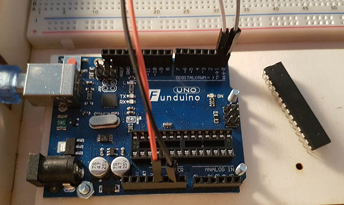
To test my program I set up my Arduino Uno as an FTDI. It's really easy, you just need to unplug the ATMega from the board and use the Rx and Tx pins in combination with the Vcc and Ground of course.
Integrated Development Environment (IDE)
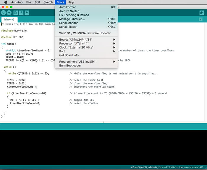
I tested 2 IDEs this week: the Arduino IDE and VSCode/Platformio. The Arduino IDE is graphical, intuitive and overall very easy to use. You just need to specify the board and the programmer you're using in the menu and then upload your code.
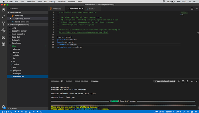
I quite like the interface of VSCode too. It looks very sleek and profesionnal. You have to be careful not to forget to set up the ini file with the board and the programmer.
Conclusion
Achievements
I'm very happy with what I've accomplished this week. It was a complicated topic but I'm quite confident with my programming abilities now. And I can't wait to take on bigger challenges!