Week 8: Computer-Controlled Machining
03/12/2019 - Stéphane Muller
This week, as a group we needed to test runout, alignment, speeds, feeds, and toolpaths for our machine. And the individual assignment was to make something BIG with said machine.
I was really looking forward to that week because I love working with wood and making furnitures. I already knew what I wanted to do and I had a couple of design ideas I wanted to explore.
Research
So the idea was to make a coffee table for my girlfriend and be creative with the design. Together we came up with the idea of machining a 3D cityscape of Paris for the table top and fill the void with epoxy. The first challenge was to find a (free) 3D representation of Paris.
I thought I could get the 3D from Google Earth, but all the tutorials explaining how to do it were outdated and didn't work. Google does not share this data unfortunately. Next idea was to get the same kind of data from Openstreet Maps. I found the plugin OSM2World and made some tests but it only works for small areas (and not well).
I found some nice models but all were for sale.
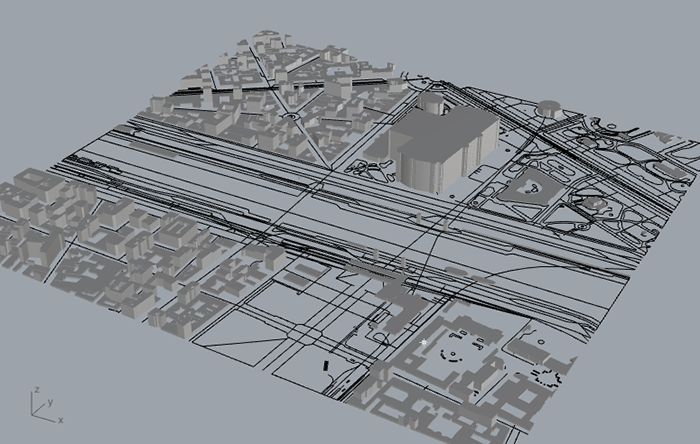
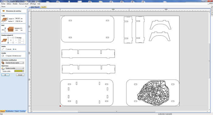
I found CADmapper which is really cool though. It's free for areas under 1 square kilometer and not that expensive upwards. You can export 3D Rhino files with buildings and topography or very detailed vector files. Here's an example of downtown Paris. Monuments are not hardly recognizable, but the rest is very good.
Doing all this reasearch and playing with some 3D models got me thinking about the feasability of it all. Especially with an area as big as Paris on such a small surface. So I looked for some other inspiration and found this.
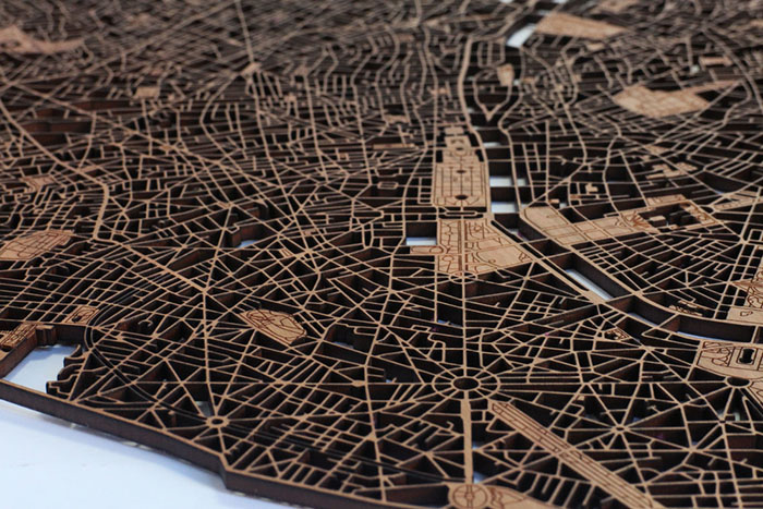
And that was it. This will be part of the table top (or something approaching). Now on to planning.
Planning and list of tasks
As this is rather experimental and might take some time to make, I decided to use spiral development for this project. I would be doing the structure of the table first, in order to validate the week. And then I would add decorative elements like the table top, drawers, etc...
- Designing the table
- Characterizing the machine
- Machining the table
- Finishing touches and assembling
- Improving on the design
Step by step
Group assignment
Check out our group documentation.
Designing the table
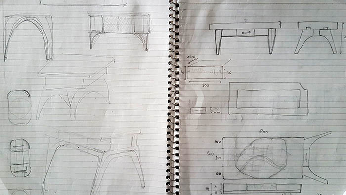
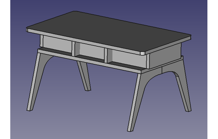
I started out with some rough sketches and the desired dimensions, but I soon realized I needed a 3D view to have a better idea of the proportions. So I played with FreeCAD a little, but after hours of tinkering I wasn't very satisfied with the result and neither was my client.
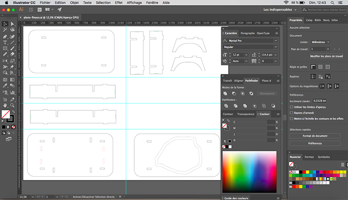
We brainstormed for awhile and came up with a simpler design, with curved angles and better proportions. I didn't feel the need to model it in 3D this time and instead decided to design the plans directly in Illustrator.
Characterizing the machine
Group assignment...
Before I could do the machining I wanted to make sure my joinery would actually work, so I designed a "quick" test in VCarve and machined it.
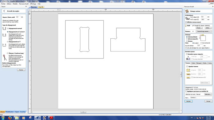
This phase was critical because my first try didn't work (neither did the second actually) and it enabled me to find the dogbone feature in VCarve. I looked for it on Google but only found a plugin that worked with VCarve 9 (we have VCarve 8 installed).
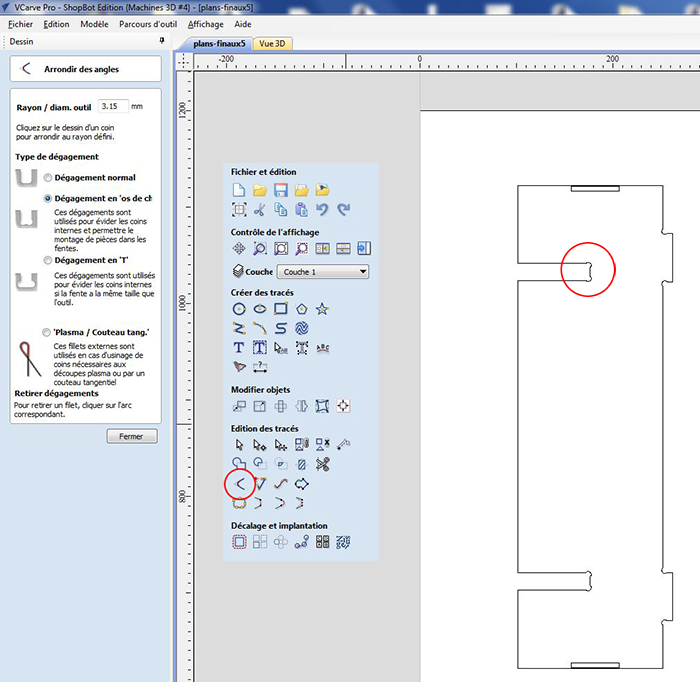
To make a dogbone, you need to click on the "round angles" tool and on the next screen select "dogbones".
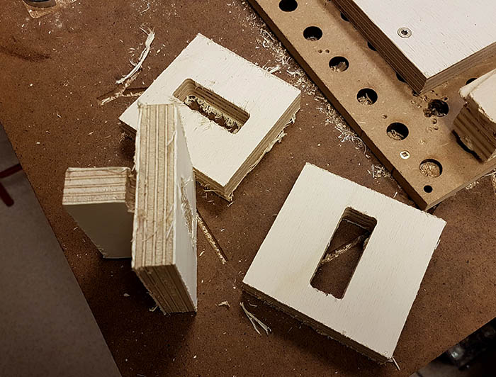
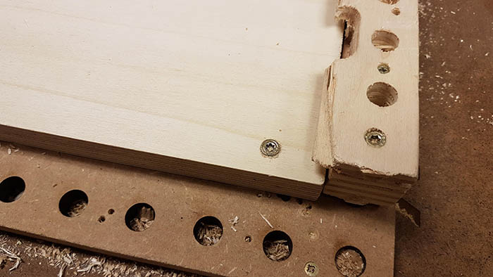
As you can see on the picture below, the first joinery didn't work. The dimension of the mortise were good, but the tenon was 0.7 mm too big. So I made the mortise 0.8 mm larger for my second try. Still wasn't enough. 0.9 mm finally did the trick.
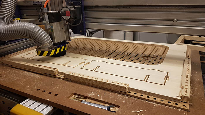
Machining the table
I made the necessary adjustments on my plans, double checked everything and started the machining process. Here are the steps I took for each wood board I machined.
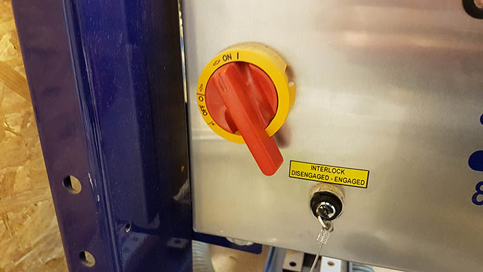
- Turn on the shopbot
- Install the right end mill in the drill
- Screw the wood plank on the sacrificial board of the shopbot
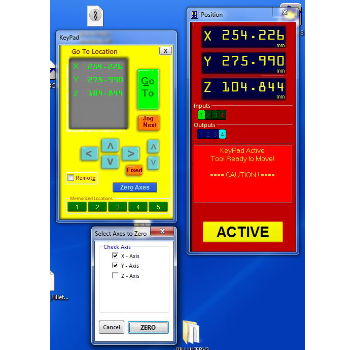
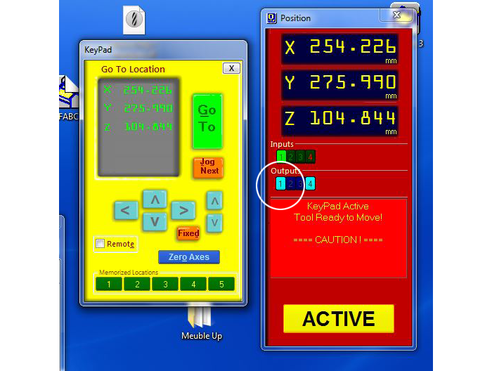
- Do the X and Y origins (bottom left of the milling area)
- Move the end mill to the opposite corner of the cutting area, to make sure everything fits
- Move the end mill to the center of the milling area
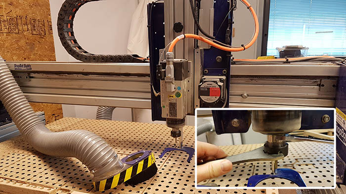
- Do the Z origin
- Let the end mill turn freely for 3-4 minutes to warm it up
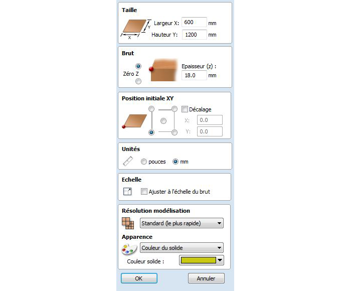
- Open Illustrator file in VCarve
- Adjust the board length and thickness
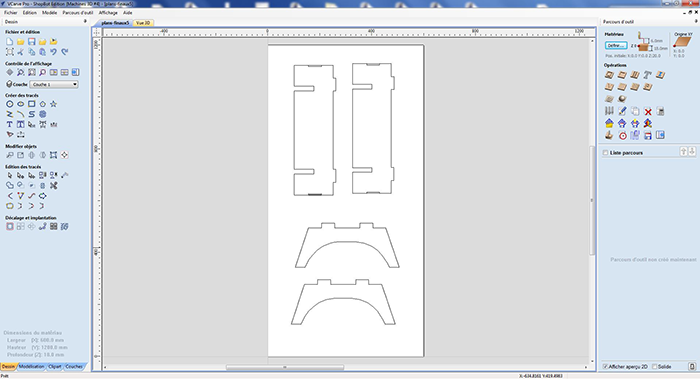
- Place the parts to be cut on the board
- Add dogbones where needed
- Set up the milling parameters (feed, speed, stepover...) for each operation (edge, hole...)
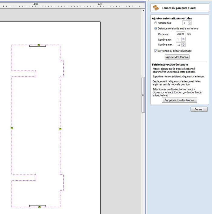
- Add tenons
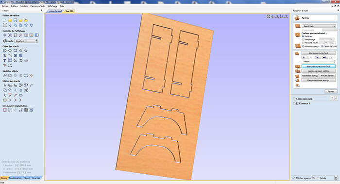
- Simulate the mill in 3D
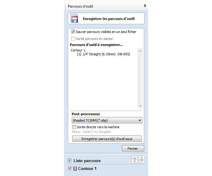
- Save the g-code and send it to the shopbot for milling
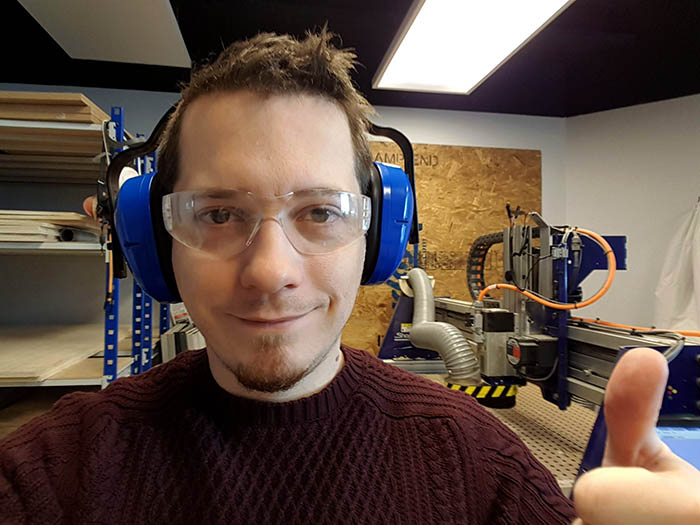
- Put on protective gear
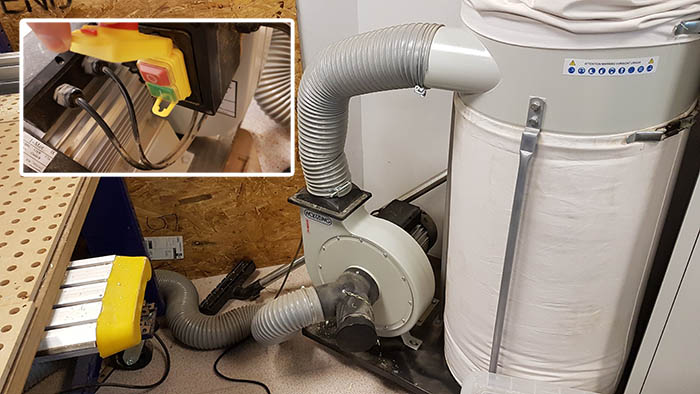
- Turn on the dust extractor
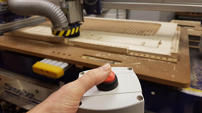
- Start the mill and keep one finger on the stop button at all times
- Wait patiently...
- Turn off the dust extractor
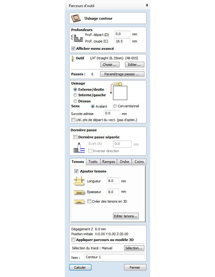
For this job I used a straight one-flute 1/4 inch mill and the following machining settings:
| End mill diameter | 6.35 mm (1/4 inch) |
| Pass depth | 3 mm |
| Stepover | 40% |
| Spindle speed | 6000 rpm |
| Feed rate | 40 mm/s |
To calculate the feedrate I used this data recommandation chart for soft plywood from Onsrud. So the formula to calculate the feedrate is: Spindle speed (RPM) x number of cutting edges x chip load.
The chipload for the endmill I used was 0.0157, the spindle speed we use here is 6000rpm and so the formula gave me a 94.2 inches per minute feedrate, which is 40mm/s.
The right speed and feed vary depending on the material. If the spindle is too fast but the feed rate too slow, the endmill will heat up or even burn the wood. If the feed is too fast compared to the spindle size, the endmill might break because not enough material is chiped away.
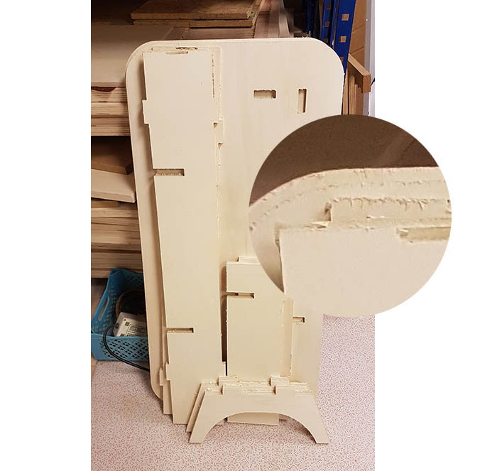
Finishing touches and assembling
The machined wood is pretty rough on the edges, with lots of splinters, as you can see on the pictures, so there was a lot of polishing to be done before assembling it.
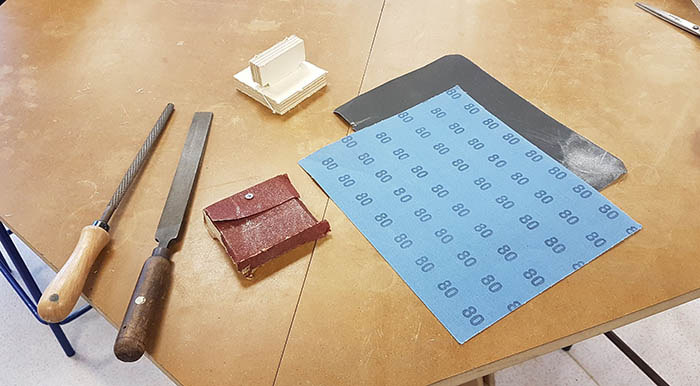
My weapons of choice for the job. I used one of my machined test squares to screw the sanding paper on it. I also used files to file down the tenons. I first sanded with a grain of 60, then 80, then 160 and finally 180 (especially for the most exposed areas of the table).
When sanding edges, always sand down, otherwise you might take some wood off the surface.
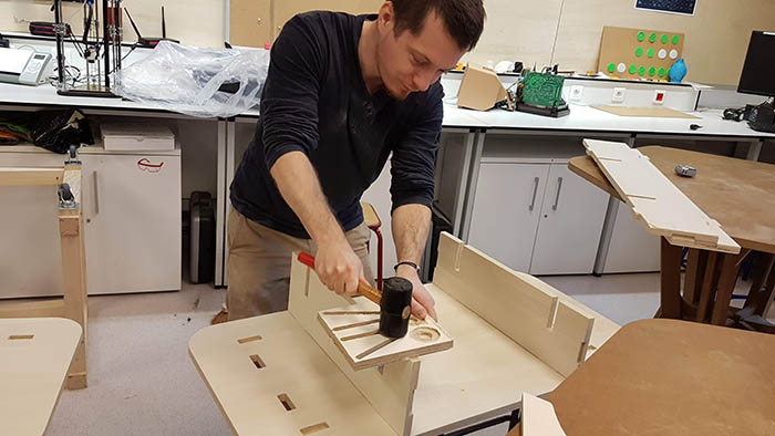
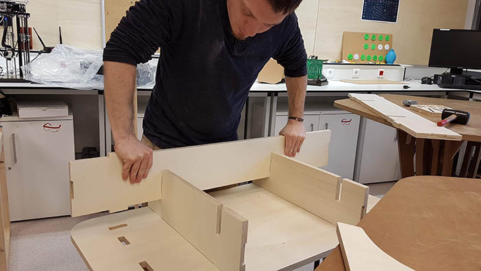
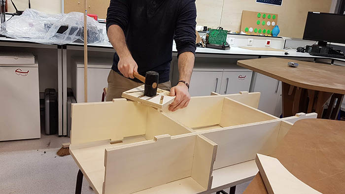
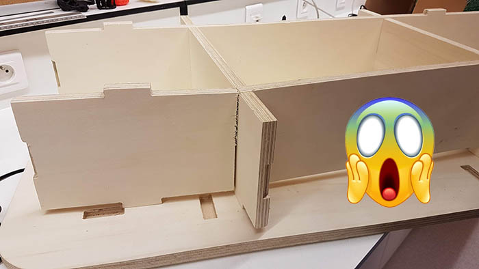
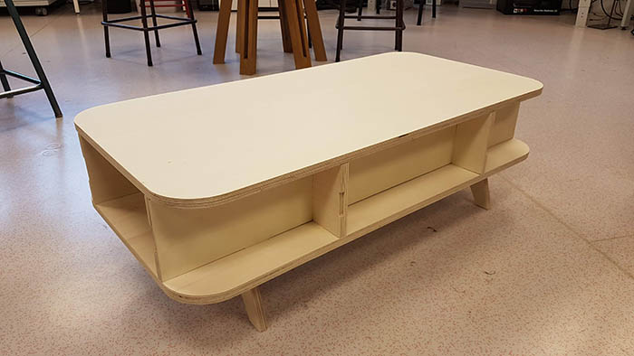
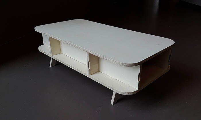
At last, it was time to assemble the table! What should have been a satisfying experience turned out to be quite painful... First I realized all my joints were 5 cm off center. Which is more an esthetics problem. It doesn't jump at you but once you notice it, it's a little annoying. And then, as you can see on the slideshow below, I forced a plank down a bit too hard and the wood broke. In the end I was still able to assemble the table and surprisingly enough, you can't even see where it's broken.
To correct my failings I have a couple of options. I can try to machine away 5 cm of the planks, but it's going to be a very delicate operation since I have rounded edges. It would need to be perfectly aligned. I will do some tests later.
A safer option would be to make new holes for the legs of the table, because that's where you notice the asymetry the most.
In any case, I will need to machine a new plank to replace the one that broke.
Improving on the design
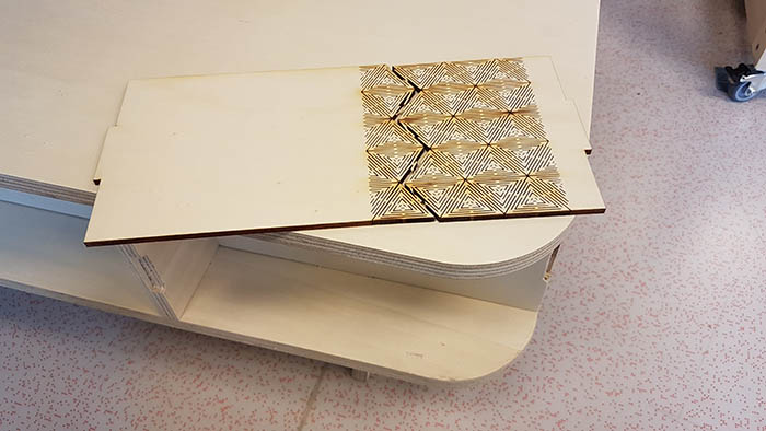
I'd like to cover the corners with living hinges, so I found some patterns online and tried laser cutting the one I liked the most. Unfortunately it didn't go so well. It probably wasn't the most flexible pattern... I need to learn more on the way those patterns work.
Laser cutting the plan Paris I designed will take approximately 4 hours... and will most probably clog the filter. But Adel tells me they'll install a better ventilation system in 2 weeks, and I'll be able to add cellulose to the filter and do the cut. So to start I'll work on a little personal project of mine as kind of a proof of concept.
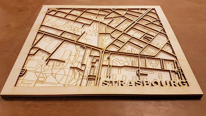
I want to make a little wooden poster of a small portion of a plan of Strasbourg, the city where I was born. Here's the result. I still need to varnish the grid, paint the parks in green and cut a plexiglass cover.
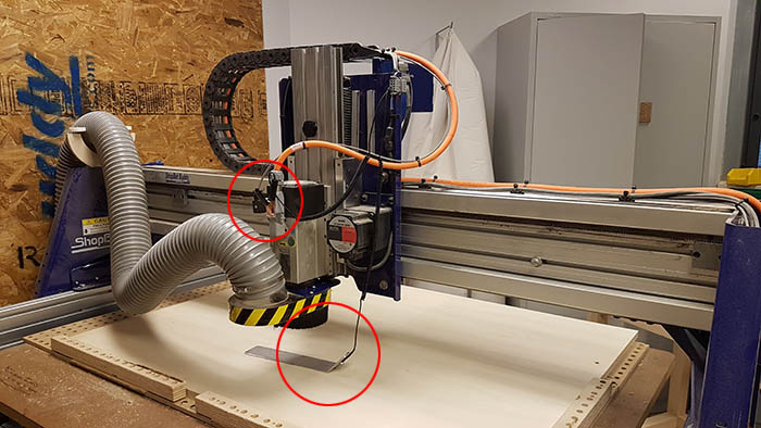
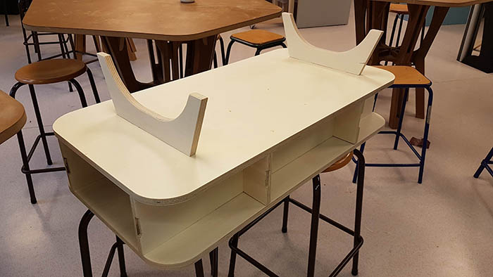
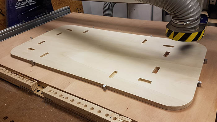
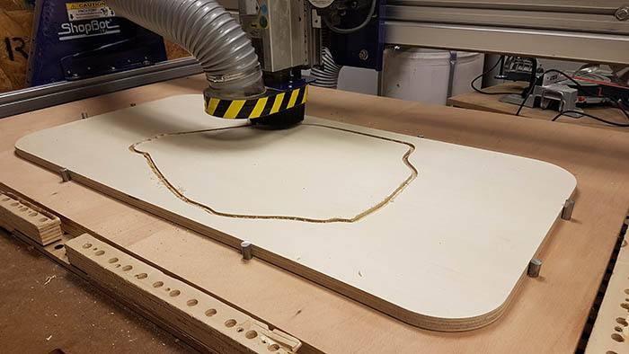
I haven't had much time to keep working on my table, but I managed to cut the hole for my map of Paris and drill some new holes for the feet (so that they look centered, to cover up my mistake). It was a challenge because I had to find a way to fix the board on the shopbot without screwing it and also trying to get a perfect x/y origin.
The solution was to use a new sacrificial board, use my original design to place holes right at the very edge of the table board and drill those holes. Then using steel stumps to block the board. It worked perfectly!
Here I will update the project with my iterations. I need to varnish the table, laser cut live hinges to cover the rounded edges and machine and laser cut the table top with the plan of Paris! To be continued...
Conclusion
Challenges
I was quite stressed to machine such a big furniture for the first time. I double checked and triple checked my joints on my plans to be sure everything was aligned and with the right dimensions, but in the end I missed a 5 cm asymetry. Which is quite infuriating. Next time I'll use Fusion 360 or another parametric design software to avoid mistakes like these. But on the bright side, everything else worked, the tolerances were good, the alignments as well and this minor hiccup aside, it looks exactly like I imagined it. Like it was right out of an IKEA catalog!
Also, wood is strong but you still need to handle it with care...
Achievements
I'm quite satisfied with the result. I think it's a good job for a first try! It felt good doing something with my hands. Giving it life in a way.