Week 11: Input devices
04/03/2019 - Stéphane Muller
Group assignment: probe an input device's analog levels and digital signals. Individual assignment: measure something: add a sensor to a microcontroller board that you have designed and read it.
Research
This week I'll start working on my final project! I'm particularly interested by capacitive sensing and step response. It's a really versatile and looks a bit magic (or very high-tech) to me.
It's a rather complicated device though and it required a little bit of research.
Some interesting ressources I found on the subject:- A video explaining the physics of capacitive sensors
- Inspiration for my final project
- The Arduino library for capacitive sensors
Planning and list of tasks
- Group assignment
- Designing the board
- Programming the board
- Testing the sensors
Step by step
Group assignment
Check out our group documentation.
Designing the board
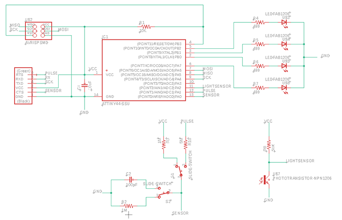
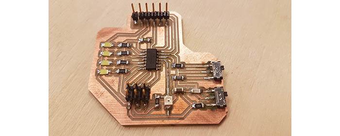
My objective here is to detect motion or proximity from a distance. Since there are two ways to do capacitive sensing, I wanted to test both approaches and test which one worked best for me. So I took both of Neil's designs (loading and transmit-receive) and combined them on one board with the help of slide switches.
Then I tried to improve the loading variant with pointers I found on various websites. I added a small capacitor (100pF) on the sensing pin to help filter the noise. And I increased the resistor (from 1 to 5MΩ) to measure higher values.
I added 4 LEDs to simulate proximity detection and changed from ATTiny85 to ATTiny44 because I needed more pins.
Finally, I added a phototransistor as a backup in case the capacitive sensors didn't work out or if I didn't get the higher resistors in time (they are not in the fab inventory and Adel had to order them). Turns out it was a good idea because we got the resistors only Tuesday and the timing was too short for me to get it to work.
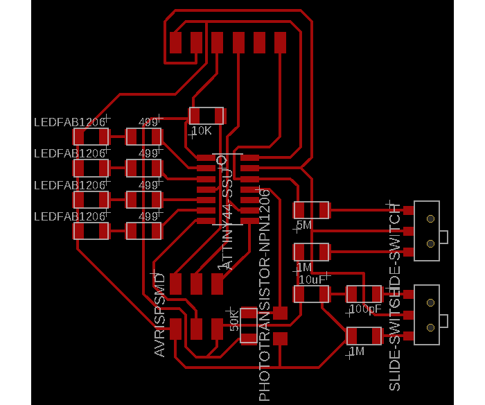
The -almost- finished board (without the high resistors).

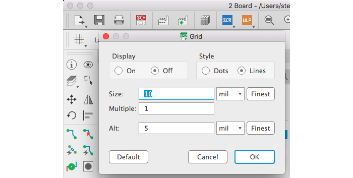
I discovered how to change the size of the magnetic grid in Eagle today... it's so much better now, when the paths aren't so close...
Programming the board
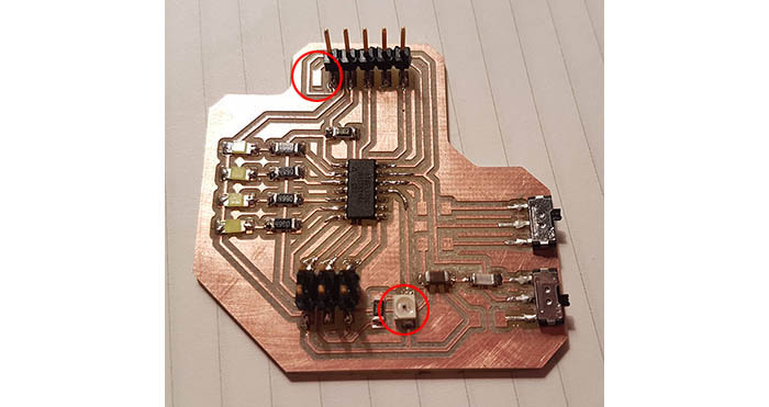
When trying to program my board I discovered 2 problems... I forgot a pin for the FTDI and I had soldered the phototransistor the wrong way. The notch on the component indicates the collector (thank you datasheet).
I was still able to work on the programming though. I spent a lot of time working out how Neil's programs worked, including the serial connection in more detail than last time because I had trouble making it work this time.
I started out with a simple blinking program to test the board.
#include
#include

#define F_CPU 8000000UL                         // 8 MHz
#define LED1 PA7                                // define the pins for the LEDs
#define LED2 PB2
#define LED3 PB1
#define LED4 PB0

int main()
{
   DDRA |= (1 << LED1);
   DDRB |= (1 << LED2);
   DDRB |= (1 << LED3);
   DDRB |= (1 << LED4);

  while(1)
  {
    PORTA ^= (1 << LED1);
    _delay_ms(200);
    PORTA ^= (1 << LED1);
    PORTB ^= (1 << LED2);
    _delay_ms(200);
    PORTB ^= (1 << LED2);
    PORTB ^= (1 << LED3);
    _delay_ms(200);
    PORTB ^= (1 << LED3);
    PORTB ^= (1 << LED4);
    _delay_ms(200);
    PORTB ^= (1 << LED4);
    PORTB ^= (1 << LED3);
    _delay_ms(200);
    PORTB ^= (1 << LED3);
    PORTB ^= (1 << LED2);
    _delay_ms(200);
    PORTB ^= (1 << LED2);
  }
}
As I had 4 LEDs, I had a little fun and made a "kit" looking animation. And this time I used the delay library instead of interrupts. As you can see the program is very straightforward... but at first it wouldn't work because something was off with the clock. Last time we used a resonator, this time we're using the internal clock and I couldn't figure out for the life of me what was wrong. All my settings seemed right in the Arduino IDE.
After some research I figured it must be because the fuses weren't set correctly. Apparently it's possible to set the fuses by burning the bootloader, so that's what I did. It didn't work straight away, you have to reset the power of the MCU for it to work.
Then I wrote a simple routine to display the level measured by my sensors with the 4 LEDs.
void displayLevel(int16_t measure)                                                // function displaying the intensity of what the sensor is getting
{
  float level = (float) measure*1024/CALIBRATION;                                 // define the maximum value here

  if( level<50 )
  {
    PORTA = (0 << LED1);
    PORTB = (0 << LED2) | (0 << LED3) | (0 << LED4);
  }

  if( level>=50 && level<256 )
  {
    PORTA |= (1 << LED1);
    PORTB = (0 << LED2) | (0 << LED3) | (0 << LED4);
  }

  if( level>=256 && level<512 )
  {
    PORTA |= (1 << LED1);
    PORTB = (1 << LED2) | (0 << LED3) | (0 << LED4);
  }

  if( level>=512 && level<768 )
  {
    PORTA |= (1 << LED1);
    PORTB = (1 << LED2) | (1 << LED3) | (0 << LED4);
  }

  if( level>=768 && level<1024 )
  {
    PORTA |= (1 << LED1);
    PORTB = (1 << LED2) | (1 << LED3) | (1 << LED4);
  }
}
It's a simple routine that takes the measurement and divides it into 4 thresholds. The first little calculation is to calibrate the display with the maximum value we're expecting.
Next, I took Neil's code for the phototransistor and adapted it to the ATTiny44. The bits and registers for the ADC aren't exactly the same. It was a good opportunity to figure out how it worked.
int main()
{
   uint16_t measurement = 0;
   static char chr;
   char str[10];

   DDRA |= (1 << LED1);                                                           // define LED pins as outputs
   DDRB |= (1 << LED2);
   DDRB |= (1 << LED3);
   DDRB |= (1 << LED4);

   CLKPR = (1 << CLKPCE);
   CLKPR = (0 << CLKPS3) | (0 << CLKPS2) | (0 << CLKPS1) | (0 << CLKPS0);         // clock is not divided

   set(serial_port, serial_pin_out);
   output(serial_direction, serial_pin_out);

   ADMUX = (0 << REFS1) | (0 << REFS0)                                            // use Vcc as a reference
         | (0 << MUX3) | (0 << MUX2) | (1 << MUX1) | (0 << MUX0);                 // set PA2 as the analog input
   ADCSRB = (0 << ADLAR)                                                          // the result is stored in ADCH and ADCL over 10 bits adjusted right
         | (0 << ADTS2) | (0 << ADTS1) | (0 << ADTS0);                            // free running mode
   ADCSRA = (1 << ADEN)                                                           // enable Analog to Digital Converter
         | (1 << ADPS2) | (1 << ADPS1) | (1 << ADPS0);                            // set prescaler to 128

  while(1)
  {
    ADCSRA |= (1 << ADSC);                                                        // start conversion
    while (ADCSRA & (1 << ADSC));                                                 // wait till conversion is done (when complete, ADSC returns to zero)

    measurement = (ADCH << 8) | ADCL;                                             // store the result in variable
    sprintf(str, "%d", measurement);
    displayLevel(measurement);                                                    // display it with the LEDs

    chr = ADCL;                                                                   // ADCL and ADCH need to be read
    chr = ADCH;                                                                   // otherwise they're not updated

    put_string(&serial_port, serial_pin_out, "measurement: ");
    put_string(&serial_port, serial_pin_out, str);
    put_char(&serial_port, serial_pin_out, 10);

    _delay_ms(500);
  }
}
In the ADMUX register we're defining Vcc as our reference voltage and the analog input where the signal is supposed to be read.
Then we set the result to be stored and ajusted right. The result is stored over 10 bits in 2 different bytes: ADCH and ADCL. The difference between right and left adjusted is best explained in the picture below.

Then we enable the ADC and set the prescaler to 128.
In the main loop we start the analog to digital conversion by setting the ADSC bit to 1 in the ADCSRA register. This bit will stay set until the conversion has been completed. Then it's cleared back to 0 and that's what we're testing with the while loop next.
To read the result I concatenate ADCH and ADCL together, transform them in a string and send the string through the serial.
ADCHandADCLneed to be explicitly read by assigning their value to a variable, otherwise they won't be updated by the ADC.
Now I had some trouble with serial this time, I kept getting strange characters. So I tried to understand how Neil's serial communication worked and what the baud rate and bit delays were. So a baud rate is just the number of bits per second sent. And at some speeds and some clock rates, MCUs generate more errors. To choose the right baud rate you can refer to this table.
The bit delay, as it is mentionned in Neil's program, is the time used by each bit for the corresponding baud rate. So, at 9200 baud we get 1/9600 = 104µs. Once I understood all that it was pretty clear nothing was wrong with the code, so I checked my connections... and I just had to switch Tx and Rx. Dumb mistake but at least I understand the code now!
To make the code a little easier to read, I put Neil's serial communication code in an include file and included it in the header.
At last I could re-solder the phototransistor, solder the missing pin, the higher resistors and test everything. Here is the final board.
Testing the sensors
With this setup I found the sensor not sensitive enough. In a very illuminated setting, the value was already as high as 680. I expected values closer to 0, like 300. Next time I'll try with a lower resistor (10K vs 50K now).
Conclusion
I've learned a lot about embedded programming and the way MCUs work this week. I thought it would be easy but it turns out there were quite a few things I did not understand.
I have just started working on the capacitive sensor and I haven't been able to make a proper reading yet. Stay tuned, this part will be covered on my final project page!