

Week 5: Electronics Production
Assignment
BRAINSTORMING
What is PCB?
PCB means Printed Circuit Board.
There are many different ways PCBs can be made by digital fabrication. But in any way, they mechanically support, and electrically connects electronic components. Circuits on PCBs have components such as capacitors, resistors, and other active devices.Because I knew absolutely nothing about Electronics, I had to start from there.
I spent most of my week studying about electronics, circuit, and components.
I also needed some basic knowledge of reading and drawing schematics, because I seriously had NO IDEA what I was doing.
(Consequently, I didn't get to programming in the week.)
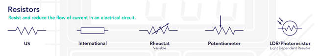
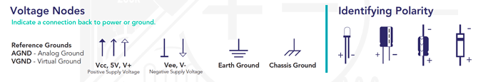
Components (and their schematic legends)

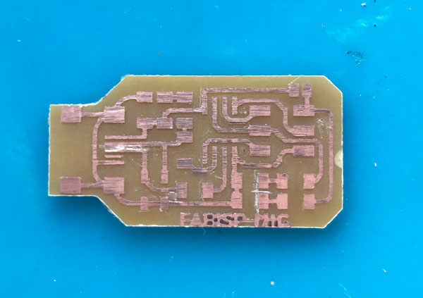
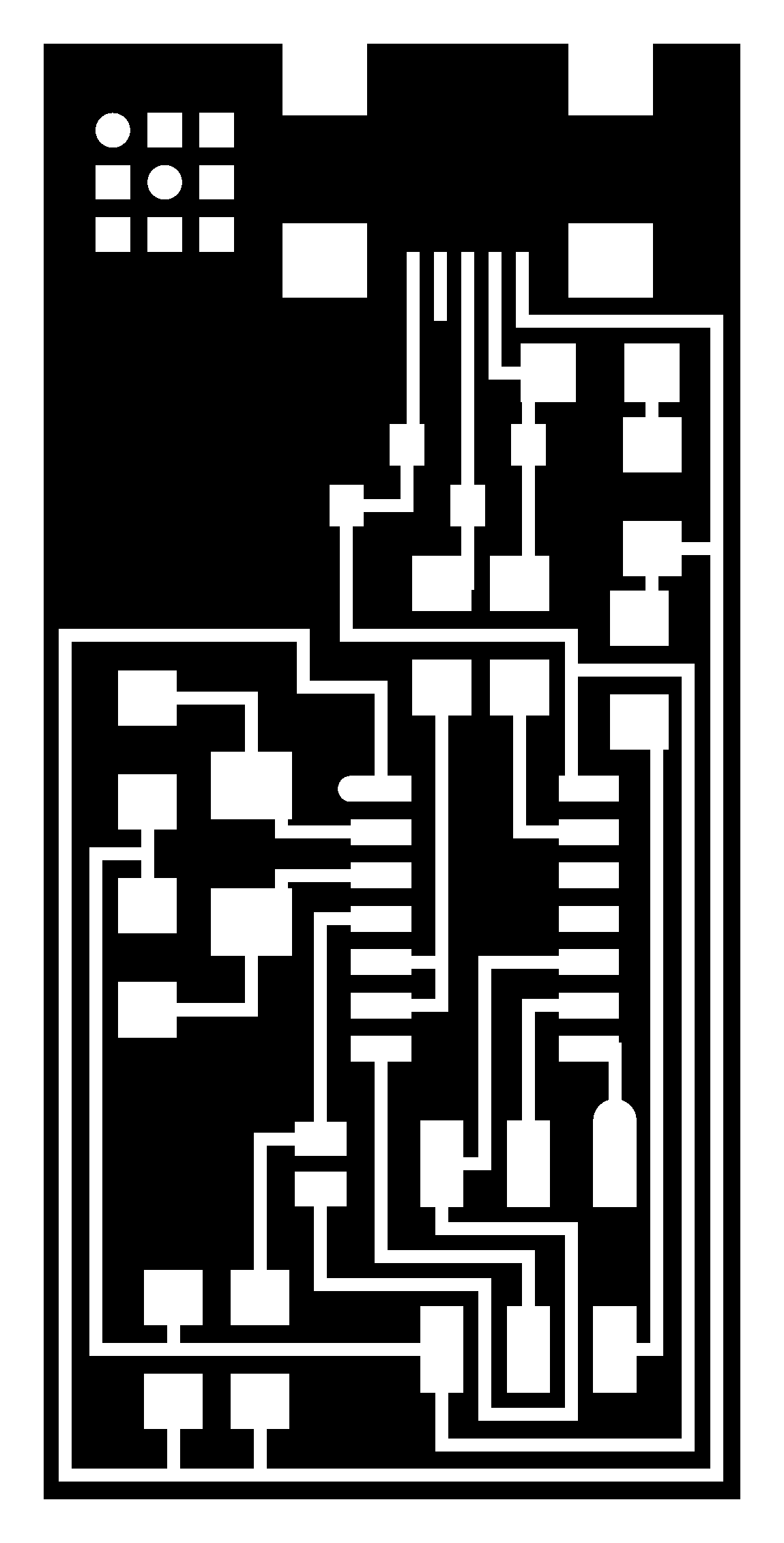
Milling your PCB
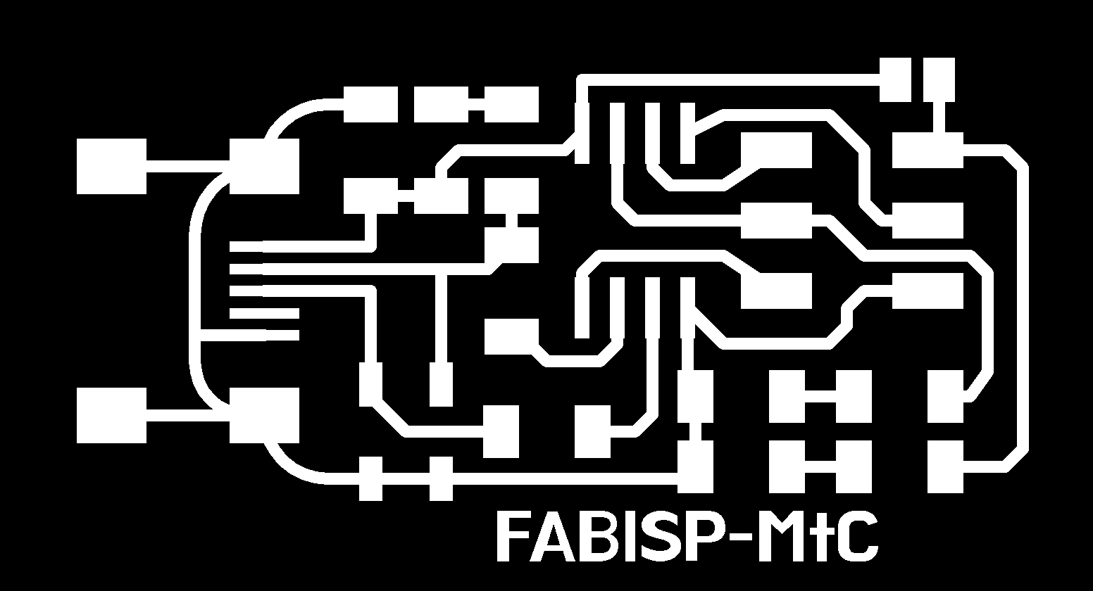

So I got his files and changed the name.
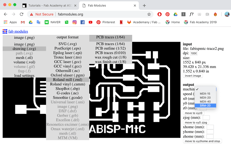 Go to fabmodules.org and load up your file.
You can choose different extensions but png works just fine.
Choose the output format accordingly to the machine you have. and then choose which cut you are doing.
Go to fabmodules.org and load up your file.
You can choose different extensions but png works just fine.
Choose the output format accordingly to the machine you have. and then choose which cut you are doing.
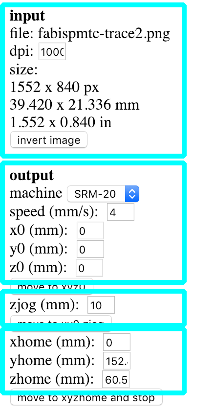 After loading your png, stats will appear on the right.
Check the input for the size and dpi (1000) Set the your machine, and speed (trace 4, cut 1),
make sure that your xyz (for your origin) is set at zero. The zjog is the setting for the height of your mill when it is moving around in action. (Set at 10 to be safe) The home xyz is for after the milling is finished, the machine come out to the front for you to check and take out.
 Under the Process section, don't change anything but the number of offset. Set howmany ever you want, but -1 to cut all the way to the edge.
 You can check your traces by clicking the 'calculate' button before saving. Click 'Save' and have it on the computer connected to your machine.
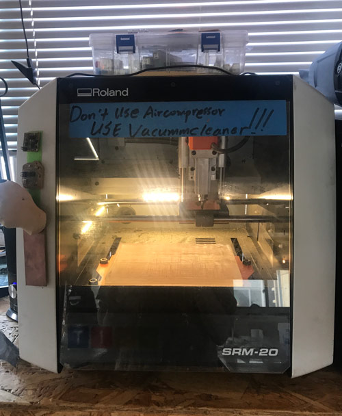
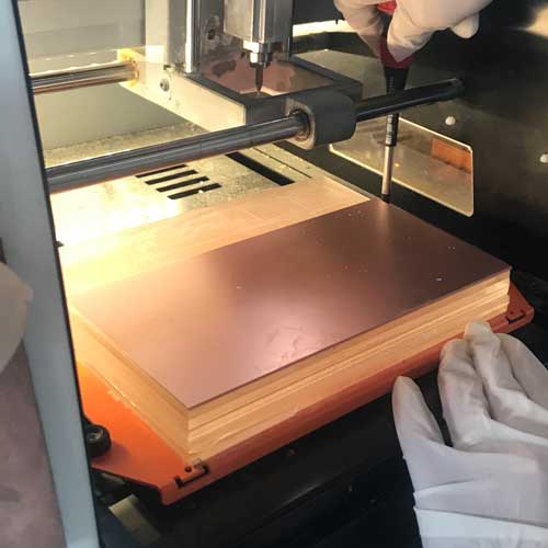
Fab Lab Seoul has a Roland SRM-20. A small desktop milling machine.
Cuttable materials are:
[Modeling Wax, Chemical Wood, Foam, Acrylic, Poly acetate, ABS, PC board]
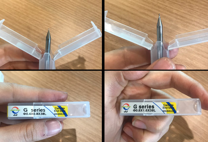
The end mills we will use this week are the 0.4mm (1/64") mill for tracing and 0.8mm (1/32") mill for cutting.
They are extremely fragile, especially the 0.4mm
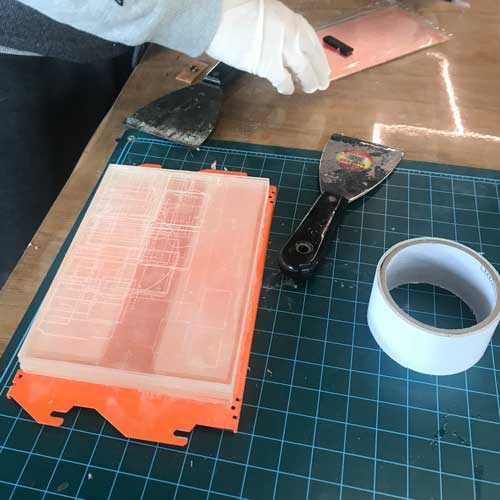
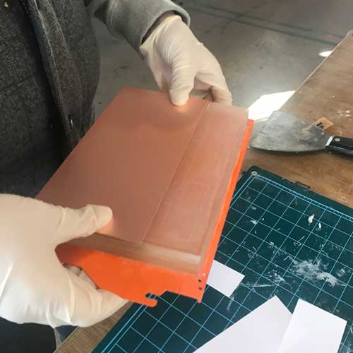
take the bed out, get a copper board for PCB making,
put double side tape evenly on the board, and stick it on to the bed.
put the board back on the machine.
(having rubber gloves is helpful as grease from your hands are bad for the board.)
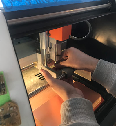
and carefully put in the appropriate end mill.
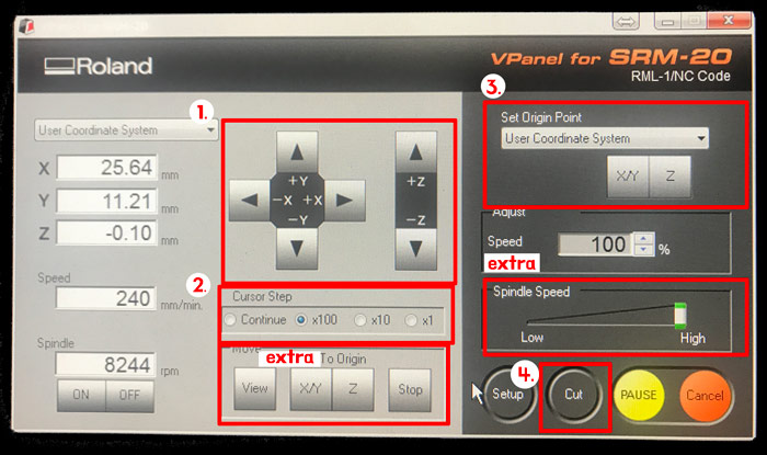
1. Like the laser cutter manually move the mill to find the origin xyz.
2. Becareful when you set your z especially, because initially it moves fast. so you can adjust the speed it moves here.
3. After you've adjusted the xyz, press set origin. [you have to get z as close as you can without breaking the mill, and adjust the z manually] after setting the Z you have to raise it back so that the end mill does not accidentally break
4. Press 'cut' to pick your .rml file and start.
Extra. you can click here to go to the origin you've set. this is useful for end mill change for the same cut.
Extra. If you haven't used your machine for a while, you might want to warm it up by checking the 'Spindle Speed'
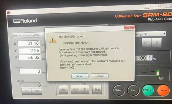
**Problem 1**
While tracing, I had an error message pop up. I couln't find the solution during the cutting so I had to cancel cutting.
I checked the manual and found the solution later on. the manual is on the links.
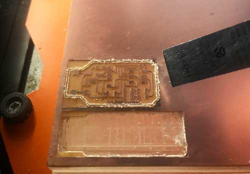
**Problem 2**
I forgot to reset the Z origin after changing the mill.
So it didn't cut all the way through the first time.
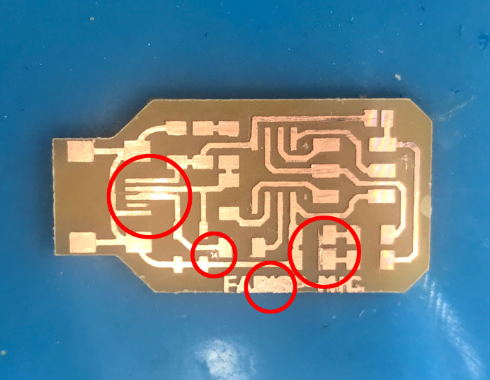
Due to the error, the last couple traces didn't happen.
So I had to clean it up manually.
Soldering
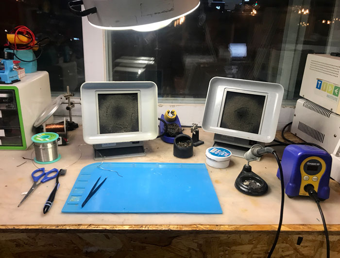
except for the height (it is a bit high for the short me).
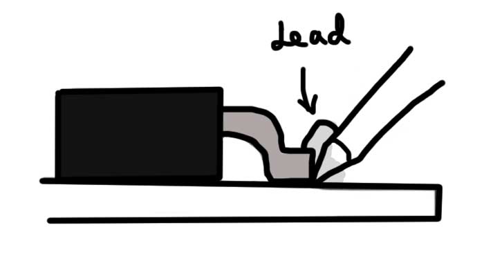
Niel's drawing from class (wait with the iron in place for 5-10 seconds)
 Start from inside out. My first try was not pretty.
I had to do it many times as well as try not to melt my board.
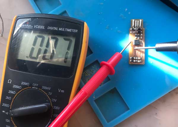
 Check with a multimeter to make sure there is no broken circuits or shorts. add the last 2X3 connecter piece.
I also added solder to the connector parts because it was advised to do so.
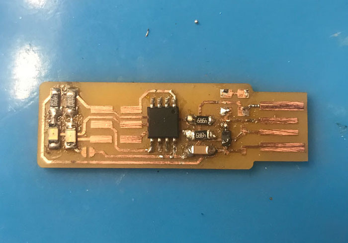
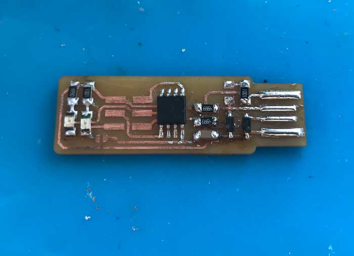
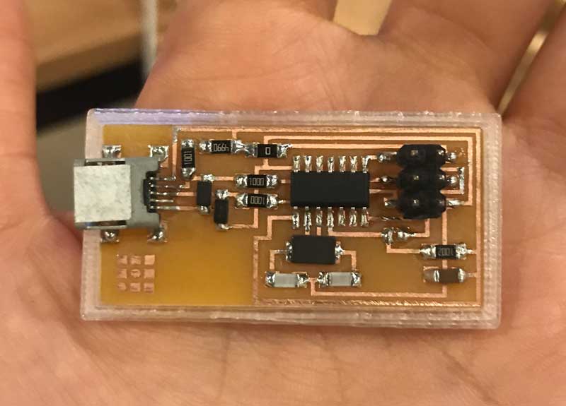
Soldering my PCB
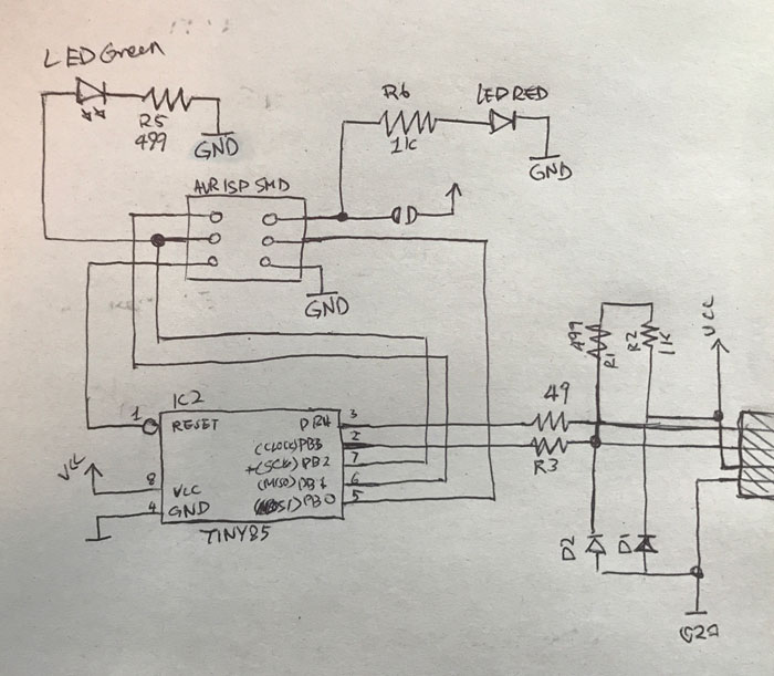 I redrew the schematics so that I could have it next to me while I solder to check.
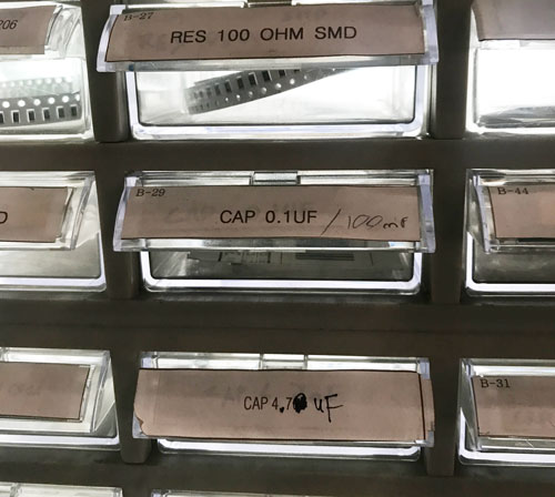
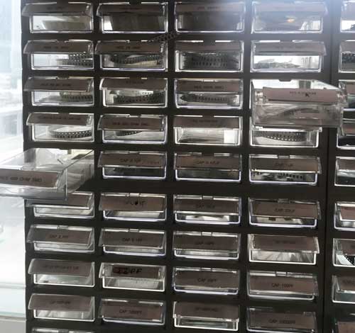
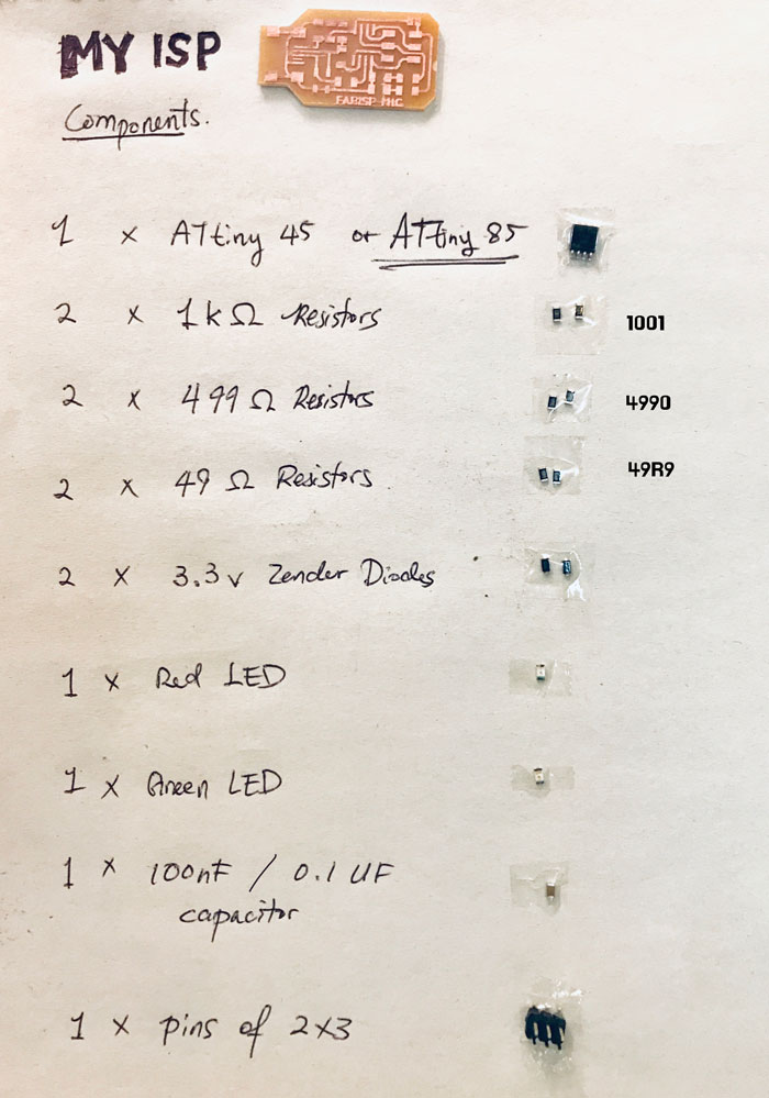 Here are the components...
 ...that was very hard to find.
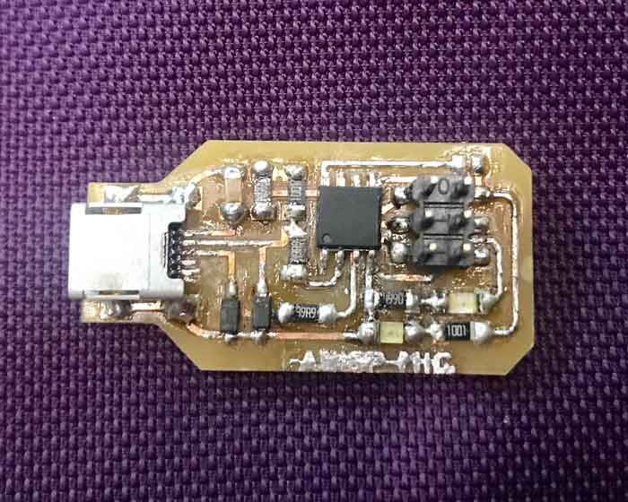 An engineer friend of my told me that I was pretty close to buring the board. I still couldn't figure out how to get the solder off of the circuit lines...
Making Connections
Connecting the new board to the computer to program.
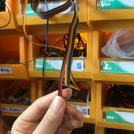
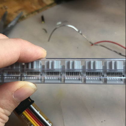
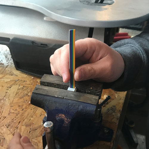 Using the rainbow cables and connectors, make a cable connector for your ISP.
make sure that when you clamp the connector on the cable, make sure they are facing
the same way on both sides.
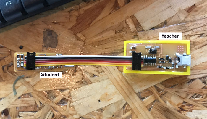 Connect the newly made student ISP (Slave) to the teacher's ISP (Master) to start programming.
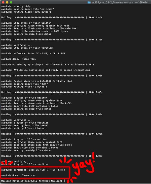
Programming
In the end, I had burnt and ripped three PCBs before I figured out what the problem was. After multiple failures, I got real good at soldering.
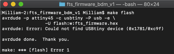
I still couldn't Program into the ISP. I tried using My instructor's ISP which works on his computer,
but I still wouldn't work. After weeks of struggling, I came to a conclusion that it is no longer my soldering problem, but the compatibility of the connection with this particular design with my laptop connector
and decided to try using a different design.
Trouble
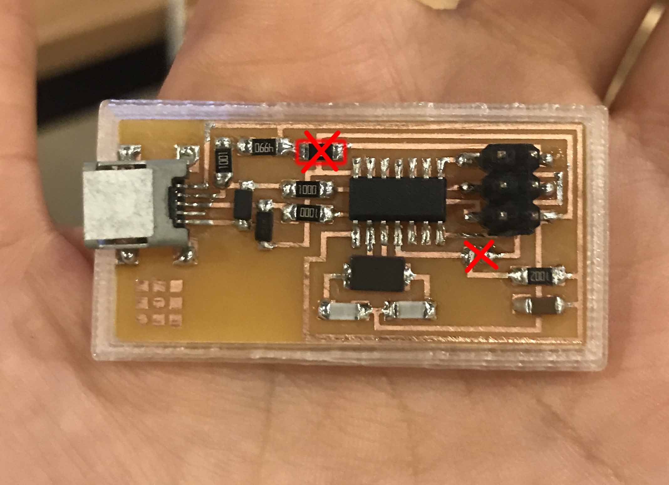 Make sure that after programming into your ISP, to make it a "Master" so that it can program other boards,
unsolder the jumper (in this case, the 0ohm resistor and the jumper) so that the ISP does not send power as well.
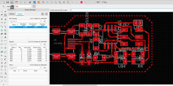
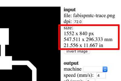 Check the unit and measurement size of your design before you start setting up on mod.
it may be too big or too small!
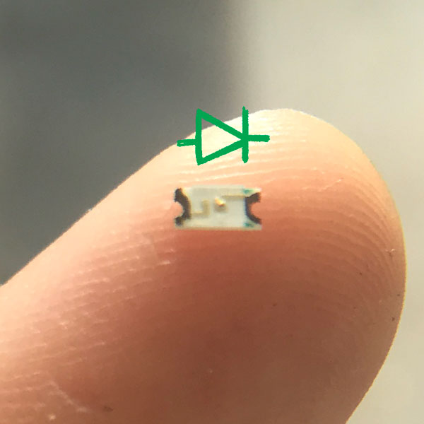 LED only works if put in the correct direction. Check the schematic to make sure.