Computer-Controlled Cutting: build your own press fit kit
In Computer-Controlled Cutting we learned how to use the laser cutter and the vinyl cutter. For each machine we were asked to develop something that can cover all the aspects we learned while using each machine. In laser cutter we were asked to design and cut our own press fit kit, and in vinyl cutter we were asked to expolre the capability of the machine by design whatever we want and cut it using the vinyl cutter.
The Group Assignment
For the group assignment this week we were asked to characterize our lasercutter parameters (e.g. foucus, power, speed, rate kerf, and joint clearance) for different type of materials. In our lab we decided to examine two different material; cardboard, and acryilic to see the performance of our lasser cutter according to the parameters mentioned when dealing with these materials.
Laser Cut Design
In the individual assignement we were asked to design a press fit construction kit that can be assemebled in different ways, and then laser cut it according it according to our laser kerf.
In desiging my press fit construction kit I used Grasshopper 3D, which is a visiual programming language and enviroment that runs with Rhino 3D computer-aided design application. I decided to go for Grasshopper because I wanted to learn a new environment and because I would like to master a new 3D modeling software, which is in this case Rhino, at the end of Fab Academy program.
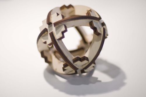
For the assignment I wanted to design and fabricate the following press fit kit. I decided to replicate a ready made design intstead of coming up with a new one, because I wanted to foucs in learnning the software rather than the desigining process.
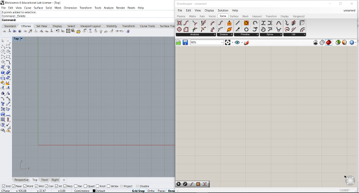
To Satrt the process I opened Rhino, and then in the coomand window I wrote Grasshopper, for the enviroment to launch.
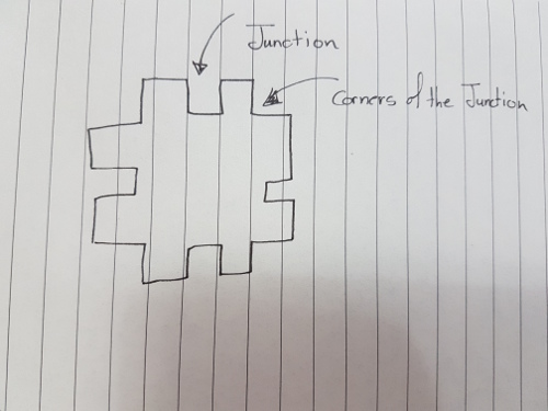
To start the design I will have first to design the square that has the four junctions, with the four subtracted corners, similar to what illustrated in the picture below.
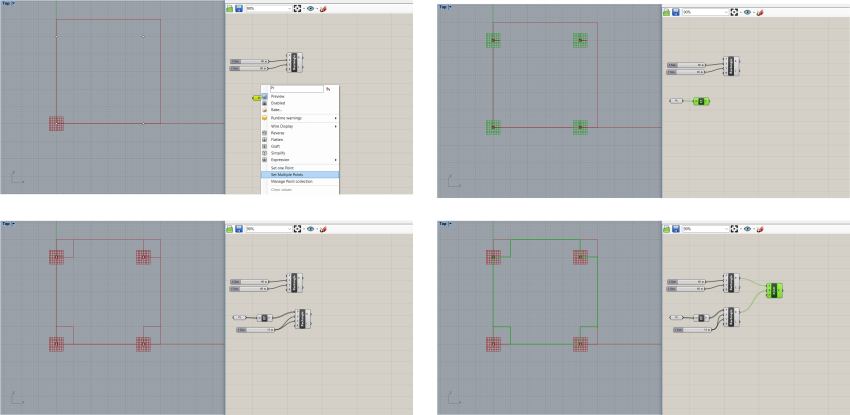
Therefore, to start, I created a sequare in Grasshopper in the XY plane, and to control the x and y length I used slider that varries from 0 to 60 mm with 10 mm steps.

Then moved to add four different points around the square. From these points I will create four squares in the corners of the big square which will help me in finalizing the outer shape of the design. After creating the squares I am going to use the "Region Difference" tool in grasshopper to substract the four corner squares from the bigger one to create the shape I am looking for.
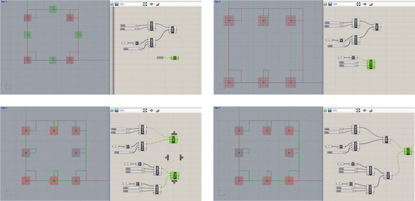
Moving on, the next thing was to start creating the junctions of the first piece. The junctions will be in the middle of each line of the square, and will be with 4 mm width since the material I am going to use is cardboard with 4 mm thickness, and 10 mm length. Following the same proceadure, I created two different groups, each group consist in two parallel points that are used to draw a squares to create the junctions. These group then are merged together, and finally with the "Region Difference" command are substracted from the main big square.
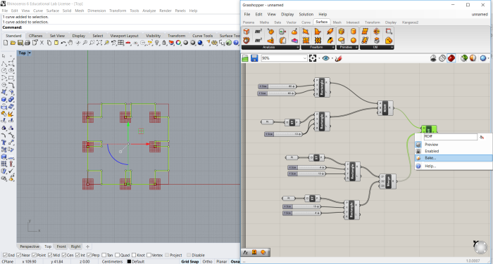
Finally to finalize the first piece I "baked" the last box in my schematic which is the "Region Difference" to be able to save the created shape using Rhino interface. The bake command will ruplicate the result of the box baked in Rhino to be able control it from Rhino interface instead of Grasshopper. After baking I exported the final result to DXF format so I can use it with the laser cutter software.
Designing the second piece was much easier to design since I am more familiar with the interface now and I experinced in it when I was desining the the first piece.
The second piece was basically an arc with junctions that would attach to the other piece. To create this arc I used the arc command or box in grasshopper, and then choosed to have the arc in the y plane. Then, I added an offset for this arc for 10 mm away from the main arc, and finally closed it using two lines connecting the end points together.

After creating the the outer shape of the arc, it is now time to create the junction of it. I did the same steps I followed in the first piece, I added points, and from these points I draw a rectangle with 4 mm width and 10 mm length. After creating these rectangles I used agine the "Region Difference" command to remove these rectangles from the main arc to create the exact curve I will use in the press fit kit design. Finally, and from the Region Differnce box in the grasshopper schematic I baked the resulted curve to be able to exported as DXF in Rhino.

Laser Cutting
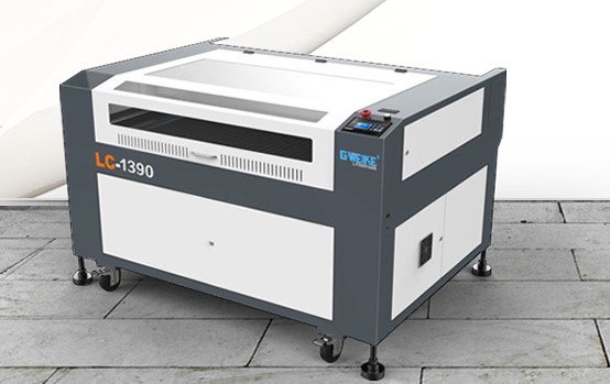
Moving on, after finishing the design, it is now time to fabricate the press-fit kit using the laser cutter. The laser cutter we have in the lab is the G.WEIKE LC1390S, it is a CO2 laser cutter, that has a maximum cutting area of 1300 x 900 mm, uses laser power of 800 W and operates at 110-220V - 50 and 60 Hz AC supplies. Despite the fact that it is a huge laser cutter, it is not one of the best laser cutter to use in general due to different reasons, one of them is that the limitation it has when it comes to the type of the material can be use in the cutting or engraving process.
The software used to operate the machine along with the machine is lasercut5.3. The software is consider to be kind of user friendly, you can easily figure your way through the software. One main drawback about this software is that it only accept vector format files, and not any other. Meaning that the software cannot accept png or JPEG files, which make the process longer for you if you wanted to laser cut or engrave a picture, because you will have to go for illustrator to auto trace it in order for the machine to recognise the file.
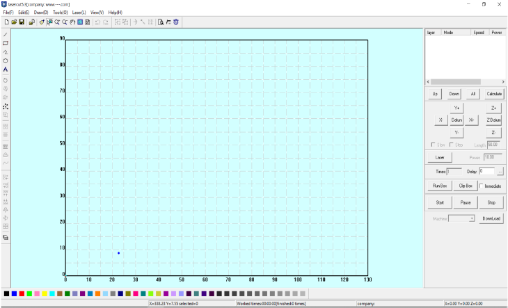
Moving on, to start the process I imported my files into the software to prepare the file for the laser cut. After uploading the files, we should set the speed and power of the laser cutter accordig to the type of material used in the process. The material we are going to use is cardboard, and according to the group assignment we did to test the settings of the laser cutter with different material, when using cardboard the speed should be maximum 20%, power and corner power should be 100%.

Finally, after preparing my files to be cutted, I save the file to a USB, and then inserted the USB to the laser cutter to setup my file and do the machine setup for the cutting.
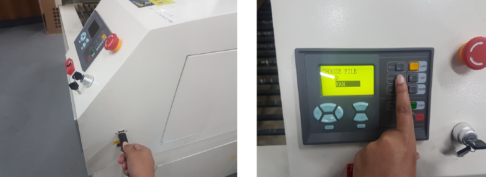
The next step is to insert my material which is the cardboard sheet, then setup my z-axis according to the distance between the laser head, and the material. There is no very specific way to adjust the z-axis, the machine doesn't have a rule on how to adjust it. However, based on the past experiments we did, we created a small tool that we hang on the head of the laser cutter, and adjust the the z-axis, until the tool fall down, to indicate that the z-axis now is adjusted.

Finally, the process of the laser cutting went succefuly, and the parts was cutted perfectly. However, my designs had an issue and it did not come out as what I expected to be, the connections between the junctions were correct, but the overall design was not as what I was looking for. The main reason behind that was because the arc I designed should not be a full arc, however it should have been half an arc for the design to come out as what should have been.
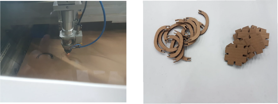
Here is the final result of the laser cutter, assembled together.

Vinyl Cutting
For the Vinyl Cutting I decided to vinyl cut the sticker I designed in the previous 2D design assignment Computer-aided Design. I did this design for my project in Fab Academy, and it illustrated the general concept of my project.

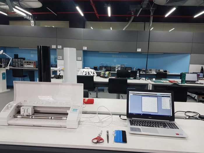
The vinyl cutter machine we have in QBIC Fab Lab is the Silhouette Cameo 3, and the software used to operate the machine is the Silhouette studio.
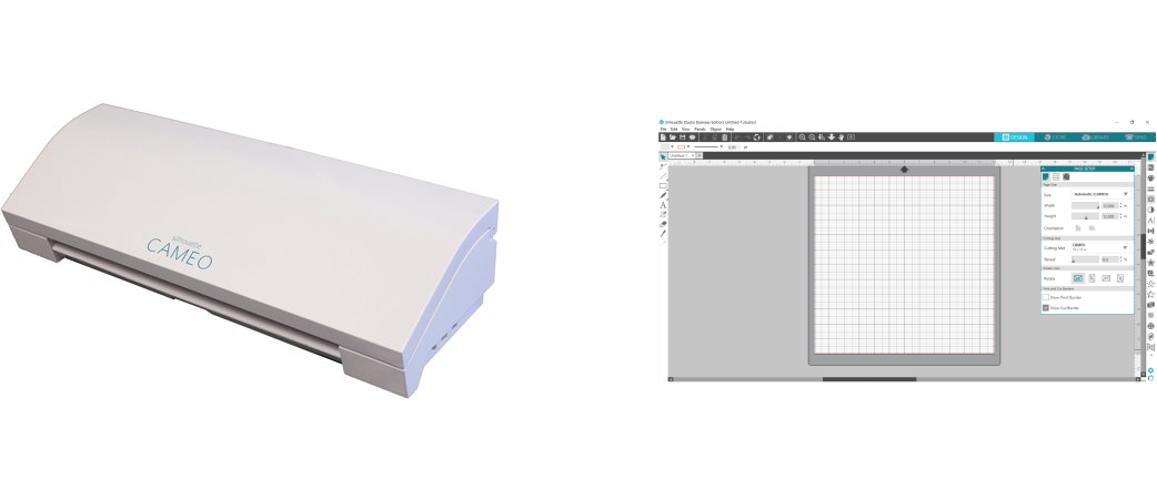
Since the design I did is quite complicated if I fabricated in one shot. I decided to fabricate it step by step in order to be able to come out they way it is suppose to be. Also, I could not find the vinyl paper in color of my logo in our inventory, so I decided to change the colors into white and black.
Moving on, I started the process by drawing two squares equal in size, wrote the name of my logo "Scanit", and cut one sequare and "anit" part of the word in black vinyl paper. And the other sequare with the first part of the word "Sc" in white vinyl paper, in order to create the first part of my logo.
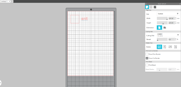
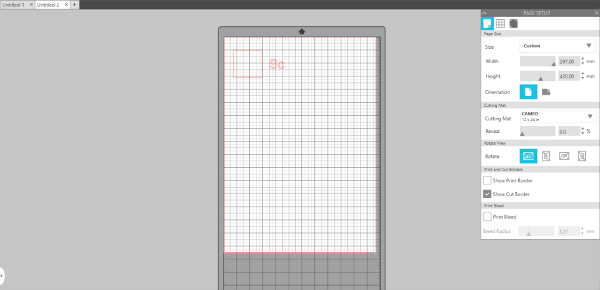
Then I did the same thing with the robotic arm part of the logo, I inserted it in the software and I traced it to get the following:
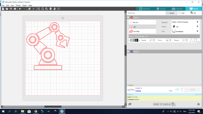
Finally I started the cutting process, here it was my steup for vinyl cutting:
As I said earlier for vinyl cutting I played mainly with two colors the black and white vinyl. Here is the cutting process.
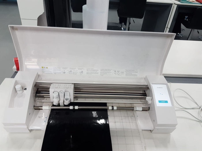
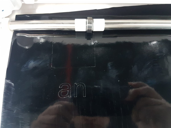
After I finish from cutting the vinyl I removed the extra vinyl then transferred the vinyl into my laptops "which is the surface I am sticking my vinyl on" using transfer paper.
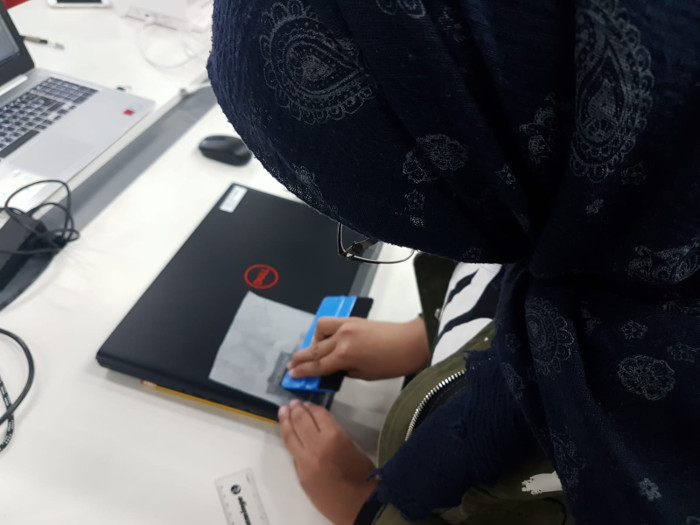
And Finally here is the final results of Vinyl cutting. I am really obsessed with the process and with the final results, and I really enjoyed doing this tattoo for my laptop.