Computer-aided Design: Make your own 3D and 2D model"
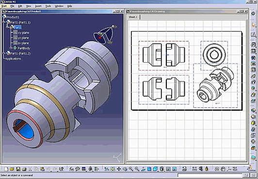
In Computer-aided Design assignment we were asked to design a 2D and 3D models using as many softwares as we can. The main idea of this assignment is to learn how to do 2D and 3D modeling, as well as to work with different open and liceaned 2D and 3D modeling softwares. This will give us the chance to discover which software we would rather to continue on working in for our future assignments, and will give us the ability to understand the pros and cons of each software to be able to get advantage of each software when using them in future
The Local Workshop
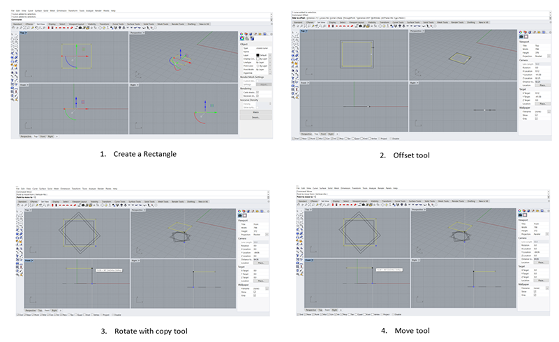
For the local workshop this time we learned how to use Rhino, which is one of the powerful 2D and 3D modeling liceaned software. During this workshop our local instructor Mr. Robert Garita, explained for us the most common and useful tools in Rhino. It was hard to cover every command and tool available, but we learned few that are useful for us when we excute our assignment like; Move, Copy, Filet, Join, Extrude, Rotate, Trim, Loft, Boolean Union, and Boolean Cut.
After the workshope we were asked to practise the covered commands by modeling either a 2D or 3D object. In my case it took me a while to digest all these commands and tools, because one I am a beginner in 2D and 3D modeling, and two it was my first time using Rhino. However, I tried my best and I came out with the following model for a plant pot. For the outer shape of the model I think it looks appealing, however this model has one negative fact or disadvantage, which is that it cannot be 3D printed because it does not have a wall thickness. Meaning saddly it can only live in my computer.

3D Modeling Using Rhino
In this assignment I wanted to do something related to my final project, which is a 3D scanning set with robotic arm connected to a circular field. The main idea of this project is to be able to scan body parts with 3D scanner that rotates around it.
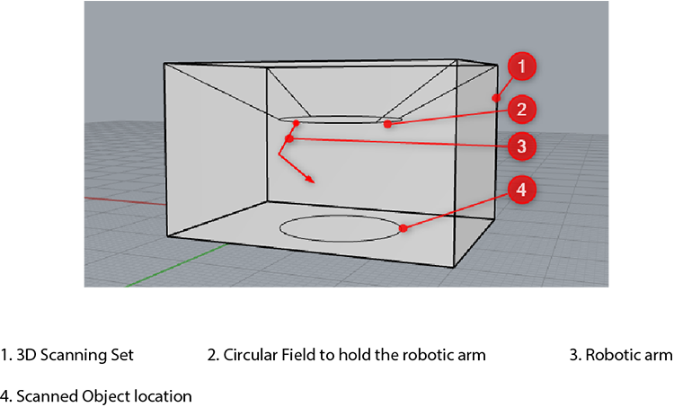
So for this assignment I decided to do part of my project, which is the tip of the robotic arm that will going to hold the 3D scanner. I tried to replecate a ready made product that is available already in market.
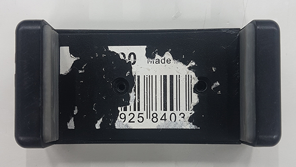
The piece consists of 3 parts, and I designed each part in different software just to try as many software as I can.
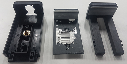
For Rhino I re-designed this piece, it is basically the sliding piece that you can move to adjust the 3D scanner inside the holder.
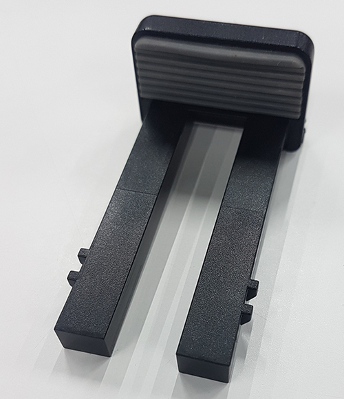
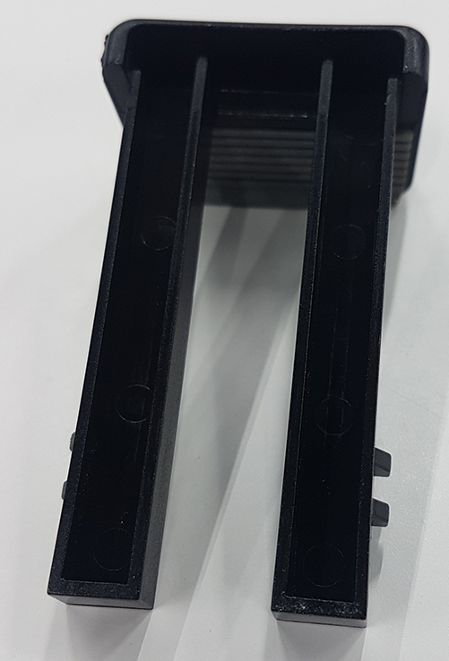
The piece has specific mechanical properties to be adjusted with other piece that it will going slide into to hold the 3D scanner. I did few adjustment to the design to make the sliding and the adjustment to the other piece easier and more comfortable for me to do it, so in the future I can easily remove it and make few maintenance if needed.
For desigining this piece in Rhino, I used most of the tools and command we learned during the local workshop we had. I was playing mostly with; offset, extudecurv, and boolean difference. However, I also used other tools and command to come out with the final design illustrated.
Duplicating or re-desigining a ready made piece in Rhino, was kind of hard for me and you can clearly see in the video the number of times I struggled tell I achieved the final result. However, I am pretty saticfied of the final result, it still need few adjustments, and for my final project I will have to go back and do few changes to the piece. But I will consider this as my first prototype for the piece.
3D Modeling Using FreeCAD
For the second piece I decided to re-design it in FreeCad.
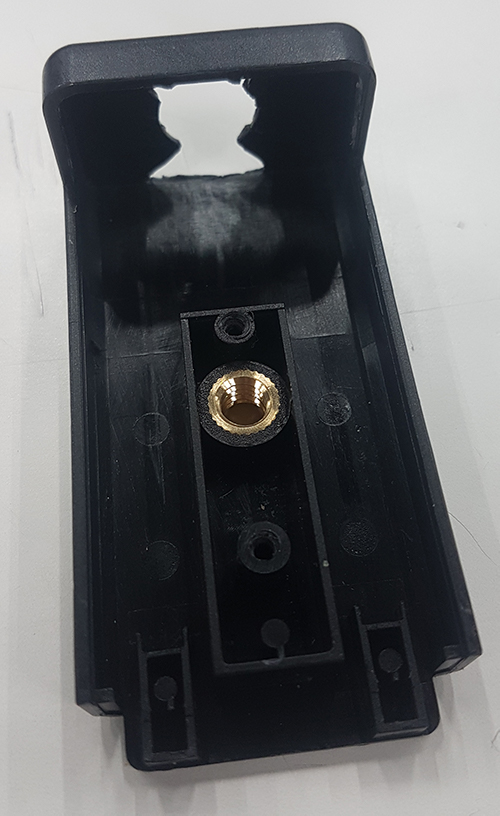
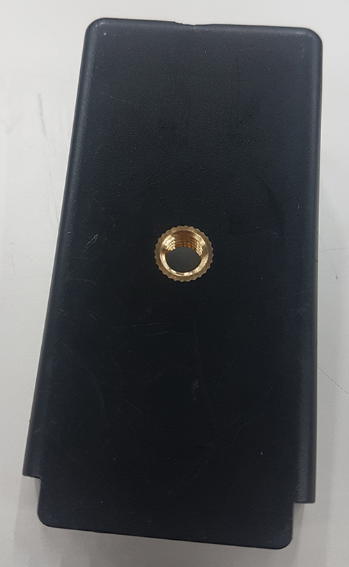
FreeCad is a free open source 3D modeling software that allows you to do a parametric desigins. FreeCAD is intended to be a feature-based parametric modeler with a modular software architecture, which makes it easy to provide additional functionality without modifying the core system.
I decided to test this software because I am still not sure about the 3D scanner I am going to use for my project, and therefore I don't know exactly the diminssion of the scanner that the holder will going to hold. Thus, and from the parametric modeler feature FreeCAD has, I was able to design thee holder using values I initiallized in spreadsheet. These values I can later on customize for my future design without going back and do the whole design from scratch.
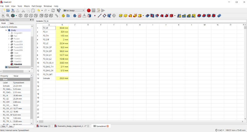
Compared to the original desigin, I could not replicate the design 100 % because I was still learning the software, and because I am totally new to the 3D modeling in general and to the parametric design in specific. However, I tried my best to form the outer shape of the model so in future I can use it to edit or add on the design it self.
FreeCAD was interesting and fun software to use. However, when comparing it with Rhino, Rhino was much easier than FreeCAD. But I really liked the idea of being able to coustomize the design without redesiging from scratch. Therefore, I decided and for my future work, I am going to use FreeCAD when I know I have to edit some parameters in the future, or when I need to use a design without being bothered that I need to consider the material thickness with the design.
2D Modeling Using Rhino
In Fab Academy I am trying to work with different softwares to gain different skills. However, it is also important for me to master one main software and use it whenevr I am desiging or 3D modeling. That is why for 2D modeiling I decided to try Rhino again.
For this assingnment I was foucsing mainly in my project. Thus for 2D modeling I was trying to design a 2D robotic arm that I can later fabricate it using either laser cutter or CNC.
Since I am beginner in the whole modeling thing, I was first experiminting how can I 2D model a robotic arm. For the first trial I designed one part of the robotic arm and it came out like illustrated below:
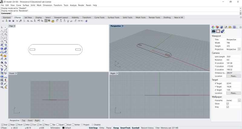
Here I was testing two things; one the type of joint I want to use to connect all parts together, and the main shape I will use to develop the arm.
The two squares are where the joints are going to be connected. The width of the square is 15 mm and the height is 4 mm which is the thickness of the cardboards we have in the lab.
From this initial shape, I came up with two designs that represent the robotic arm parts:
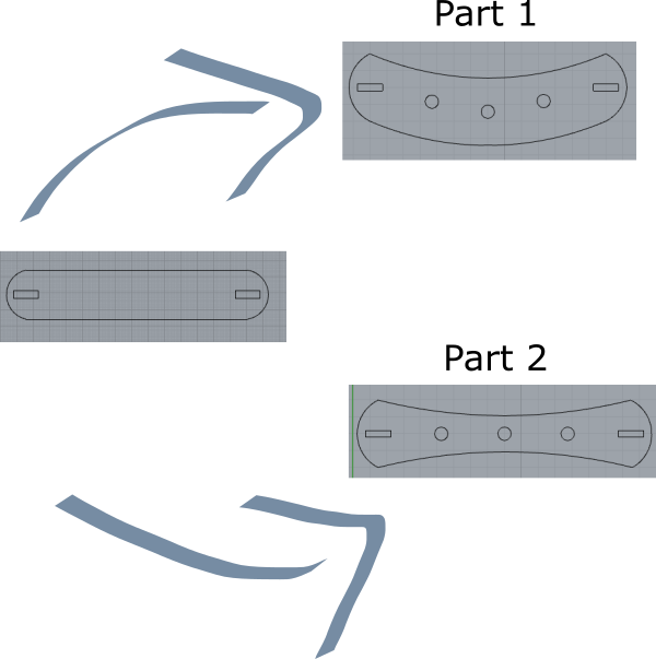
After desiging the robotic arm main parts, now I had to come up with the joints designs. For me it was important to have joints that would secure all the robotic arm parts together, and at the same time would give it a little flixability to move through an axis.
So the first joint I desigined is the one that going to connect all parts together. It is basically a rectangle with two half circles in both ends.
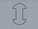
When to establish the arm movement I designed a piece that would give the robotic arm a little flexibility to move along axis without ruining the joints that hold each piece with the other. Also I designed small circle To help in securing more the pieces together when needed.
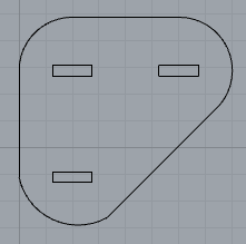
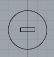
The three rectangles in this piece will be connected to the arm parts above using by the joint, this piece will ensure flixability of the arm movement and will help the joint in securing all parts together.
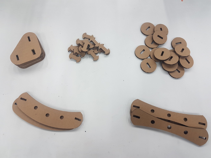
Since I am already working in a fab lab I know how to use most of the machines therefore I decided to laser cut my robotic arm to illustrate better how each part is connected to each other to form a robotic arm :).
2D Modeling Using Inkscape
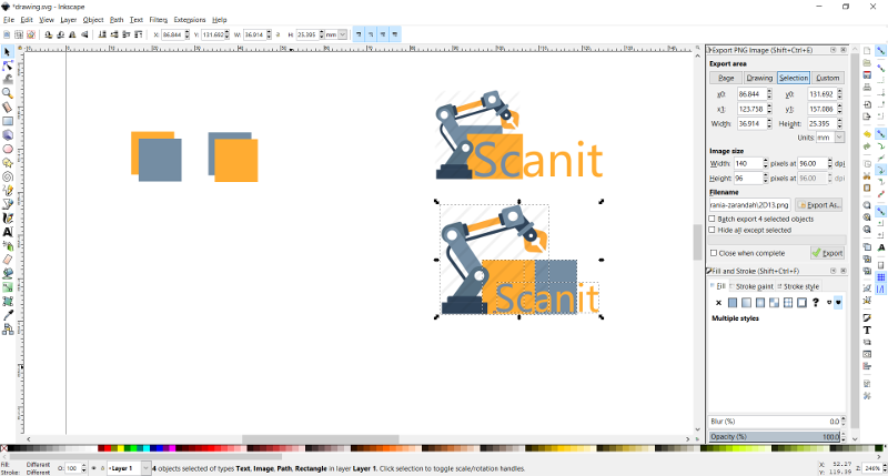
In Inkscape I wanted to do something cozy, fun, and can be use in next week assignment for vinyl cutter. Therefore, I decided to do a logo for my project.
Based on my website color theme, I tried to play with two shades in different way to see what is the better fit in terms of merging two colors together.


After deciding colors I had to decide a brand name for my project. Since I am going to work with 3D scanner using a robotic arm, I wanted to have a brand name that would at least illustrate the main idea which is 3D scanning. That is why I came up with the name "SCANIT".
Also I thought I would be great if I added a robotic arm icon to the logo so people would relate to the main idea which 3D scanning using robotic arm.
Thus I came up with these two logos. I could not decide which one is better so I added the both options here, and for the next session maybe I will vinyl cut both logos and see how would they look like in real life.


I think for now I cannot comment in my experience in working with Inkscape, because I did something extremly simple and did not take one hour from me. However, one thing I noticed about Inkscape is that it is very easy to use and you can find your tools easily, which means if you worked before with any other desiging software, you will find Inkscape the easiest to use among all these softwares.
