4. Computer controlled cutting
Abstract
This week, I have a group assignment and individual assignment related to the computer controlled cutting. Both the assignment has two part one is design and fabrication. These assignments help me to understand more about laser cutter and vinyl cutter. I have used first time Inkscape for designing for both laser and vinyl cutter. The parametric design I have started with Inkscape, it takes much time to understand the concept. Then, I switched to AutoCAD to learn parametric design. A simple structure is designed and assign the parameter list to varies the design to understand the basic concept of parametric design.
Group Assignment
What does kerf means?
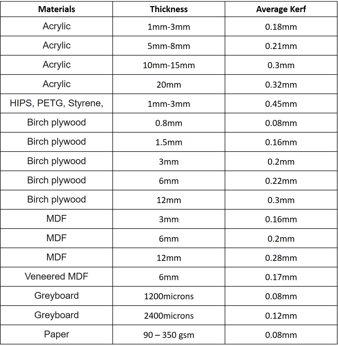
The laser burns away portion of a material when it cut through. This is known as laser kerf and it ranges from 0.08 mm – 1mm based on the material type and other conditional factors. Some of the applications of various materials with thickness and average [Kerf] (http://www.cutlasercut.com/resources/tips-and-advice/what-is-laser-kerf) are listed in the below table,
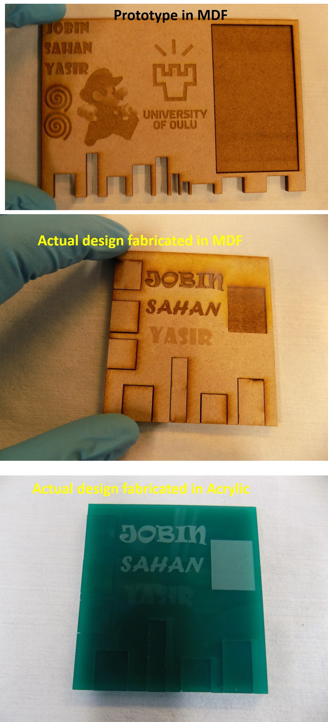
My group members are Sahan and Yasir. We are learned first about Kerf. Factors affecting kerf. What is vector and raster mode in cutting? How it influences the laser parameters such as power, frequency and speed during cutting ?. First, we make a prototype design Inkscape with line width for cutting 0.02 mm. Our designed prototype is shown in figure 1 (a). The prototype design contains group members name in dark blue color (for engraving), 2 spiral ring black in colour (for engraving), University of Oulu logo (engraving), a cartoon character with multiple colours (engraving), a rectangle filled with blue colour (engraving), 6 different rectangular cutting area in the vertical directions. The total area covered in the design is 10x15 cm2. The materials selected for laser cutting are MDF and Acrylic (3 mm thickness). Total time is taken for cutting and engraving the design taken 20 minutes. So we decided to reduce the time by short the design. The modified design is shown in figure 1 (b). Its contains vertical and horizontal cutting areas with varying size for kerf measurement after cutting both using MDF and Acrylic material board. The Vernier calliper used for measuring the cut area and cut a piece of material after laser cutting. The micrometre screw gauge is used for the engraving area. The Vernier has an accuracy of 0.1 mm, and screw gauge has an accuracy of 0.01 mm. Both measurement equipment is also shown in the figure.
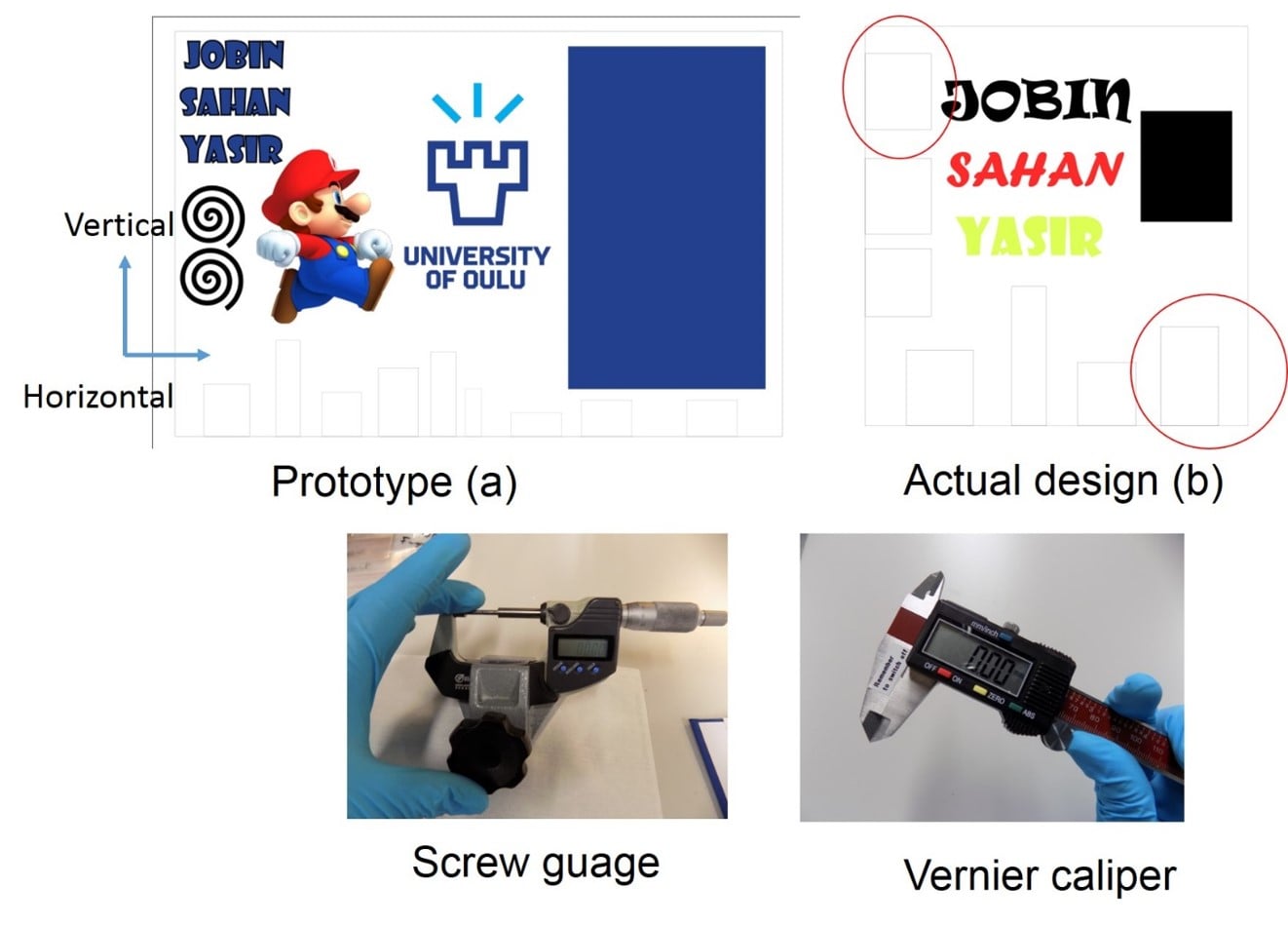
Figure 1 (a) design prototype, (b) actual design, and below images shows the instrument used for the measurements.
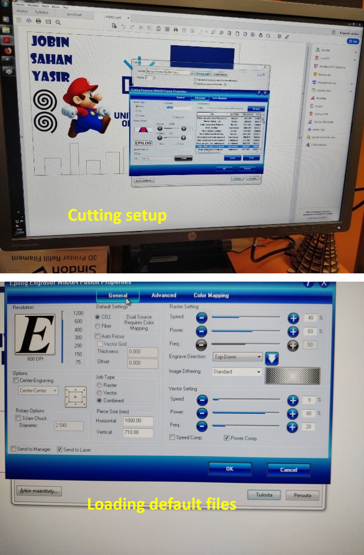
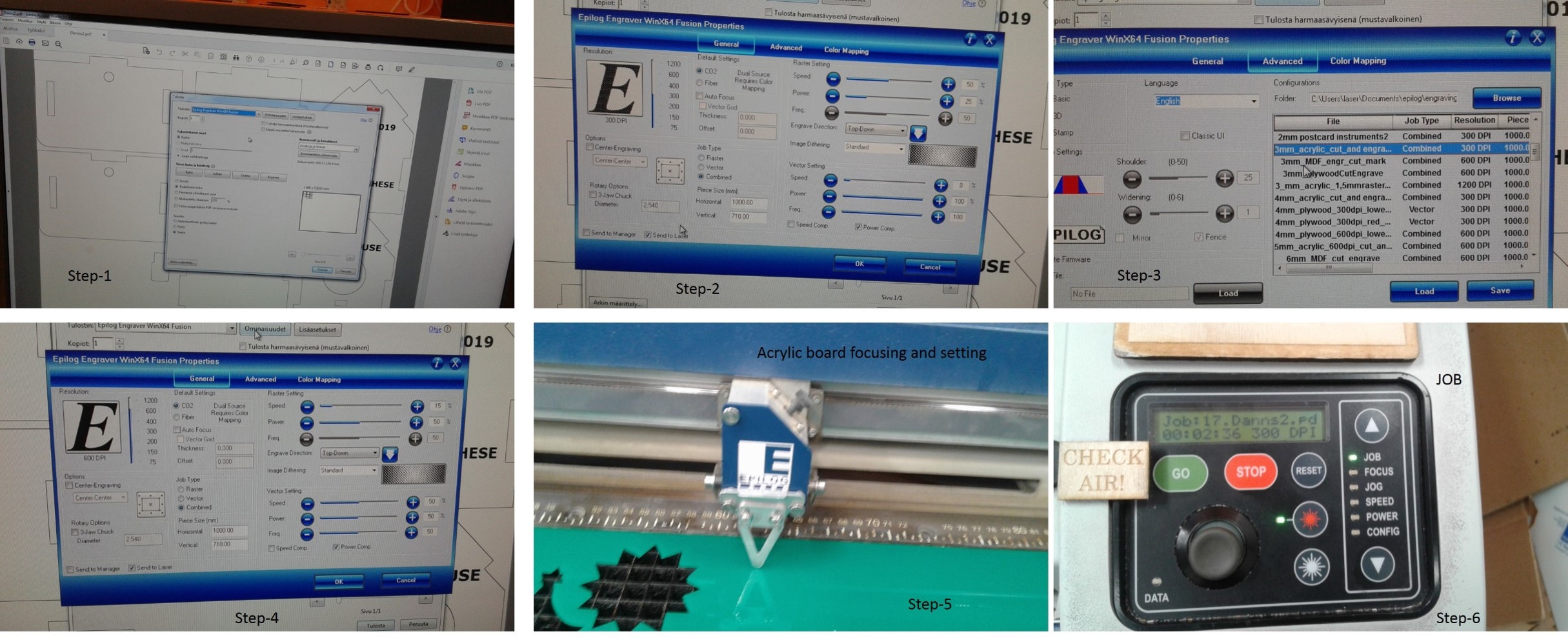
We selected one area from vertical and one area from the horizontal direction (see the area in a red circle of figure 1) of the actual design for the measurement. In actual design, we decided to use the default setting for the laser parameter for both MDF and Acrylic material board first. We have followed by changing the power, frequency and speed of the laser. We used combined mode (raster and vector) for engraving and cutting, respectively. The detailed flow chart for operating the laser cutting is shown in figure 2 (a). Figure 2 (b) presents the default laser parameter for MDF and Acrylic material board.
Laser cutting steps
-
JOG is used to set the origin for starting the cutting, and it is selected with the up and down arrows. A joystick is used to position the laser head at the start point and when in position, press the joystick to set the Jog.
-
FOCUS sets the correct height of the table of the cutter. A 2-inch aluminium piece is used to set the height by using the joystick’s up and down motions to position the table. When in place, the aluminium is removed, and the focus is set.
-
JOB is used to select the work to be cut from the printing queue. The joystick is again used, and when the right job is selected, an estimated cutting time will be displayed on the control panel.
After all the settings are done, press GO, and the cutting will start.
Figure 2 Laser cutting flowchart steps,
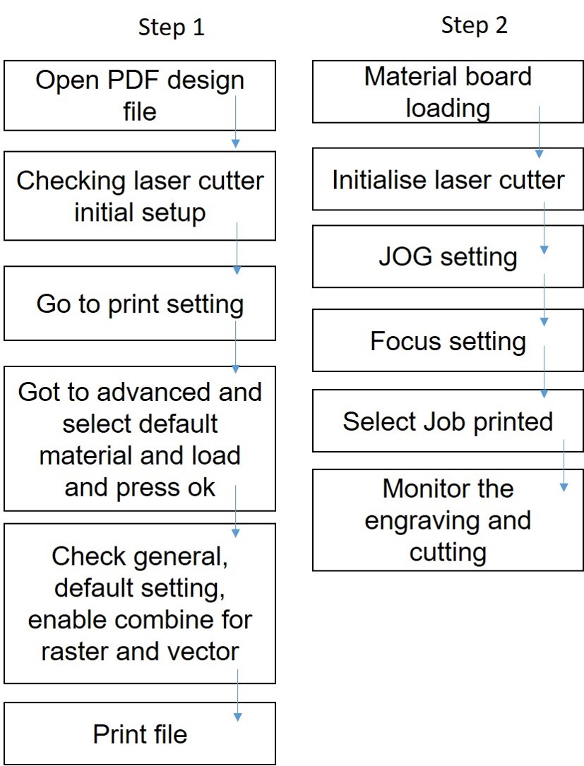
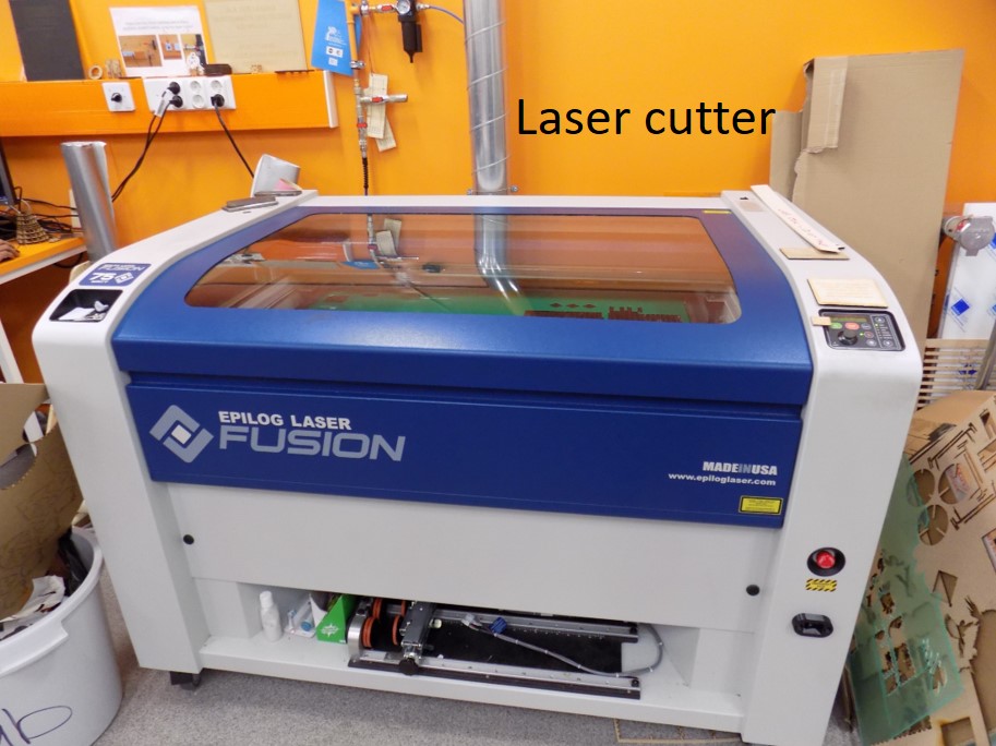
other images are laser cutter and screenshots for printing, loading, prototype fabrication and actual design for laser characteristics studies.
The detailed summary of cutting and measurement results are shown in Table.
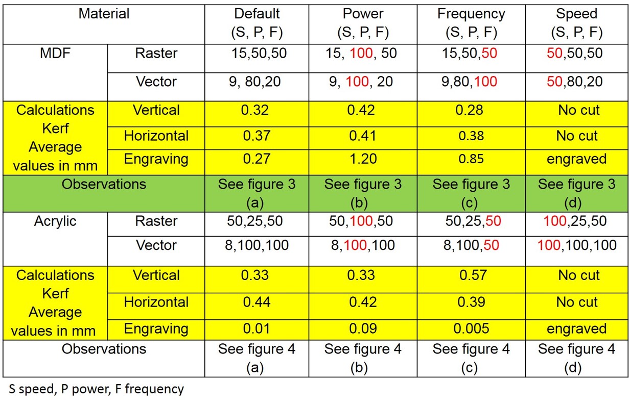
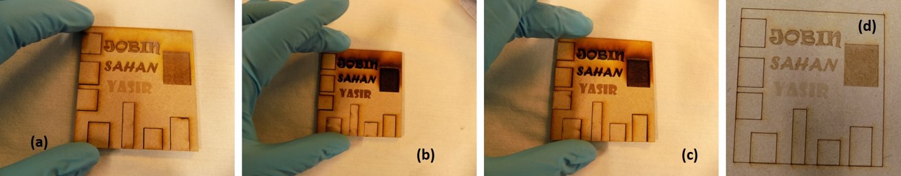
It is clear from the laser characteristics studies, laser parameters such as power, frequency and speed are interrelated. Low power is needed for cutting the sample — Raster mode, which controls the engraving. Line width is set to 0.02 mm to the design. Laser characteristics also influence on the engraving. The kerf value calculated based on the cut piece and cut area. Engraved kerf measured by actual thickness before cutting and after engraved area. Materials properties are also factors which have a critical influence on laser characteristics. Kerf is determined by material properties and thickness. However, other factors also have an impact on how much the laser takes away. The focal length of the lens, the pressure of compressed air both have an impact. Kerf widths can vary even on the same material sheet, whether cutting a straight line or a curve line or from laser cutting in the X or Y dimension. The manufacturing tolerance of the material can also impact the kerf.
Individual Assignment
Vinyl cutter design and fabrication
I have very little experience in designing new thing in Inkscape, started to learn slowly but it is easier at the final stage. I downloaded a Finland Reindeer images from google photo one complex image and one simple image and edited using Inkscape and save as PDF format for vinyl cutting.
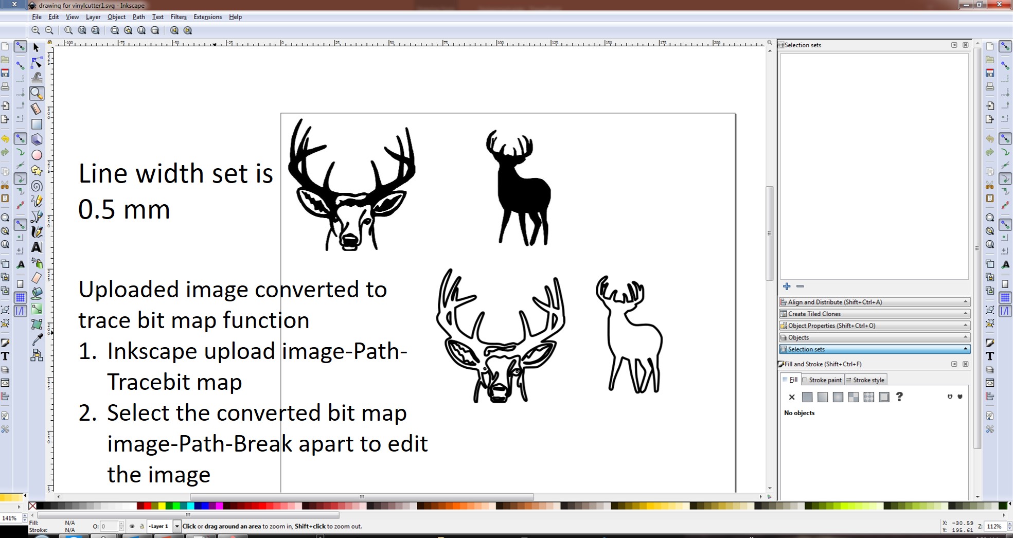
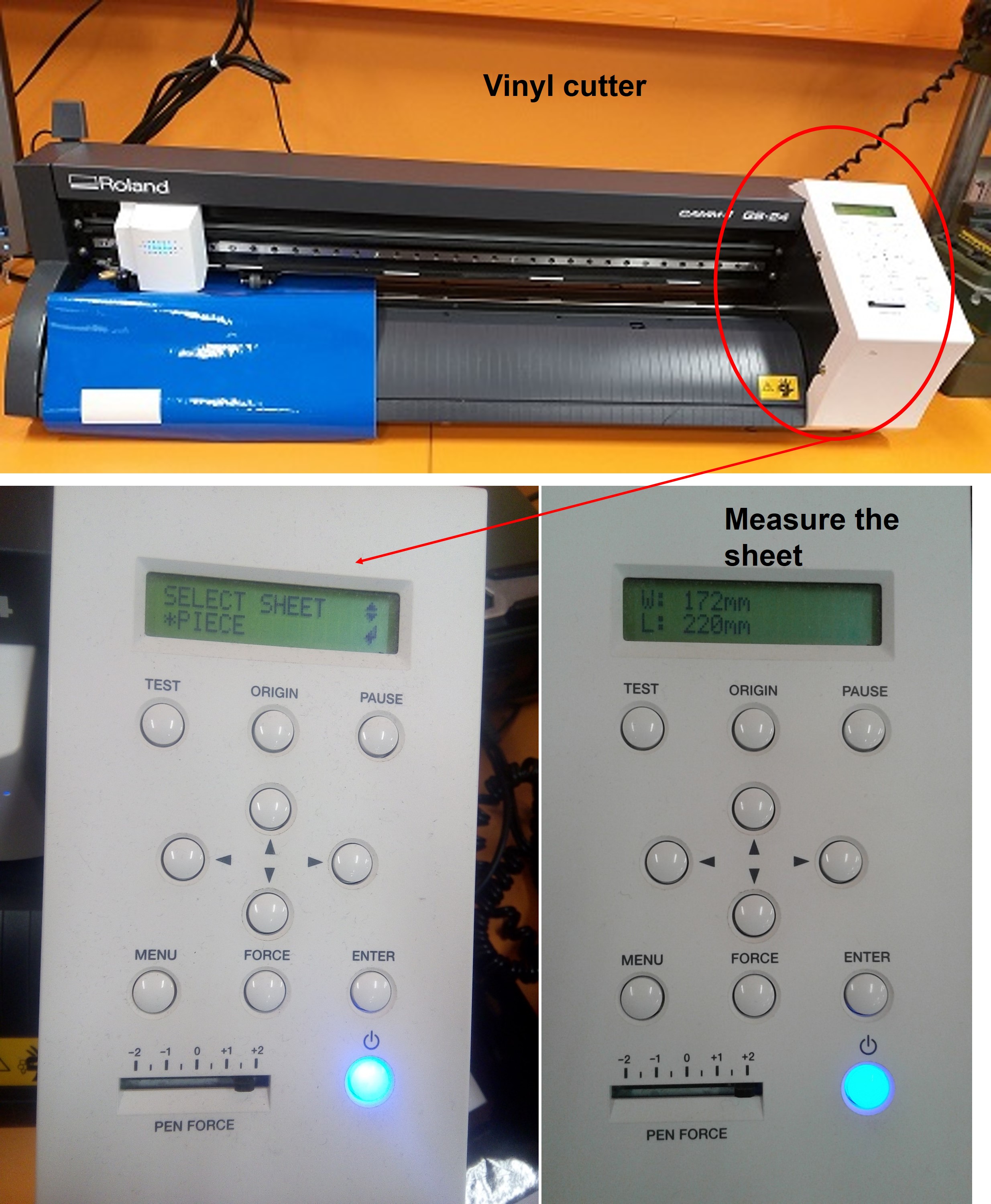
The figure shows the Inkscape design for vinyl cutter. I decided to start with 0.5 line width; all the design process steps are explained in figure and followed by using the vinyl cutter as shown in figure Initialise the cutter by set the printing paper and lock it to measure the width and high of the inserted blue colour vinyl by select and enter piece in the display window.
Vinyl cutter used is Roland GS24. Open the design PDF file in Inkscape for vinyl cutting. The cutting process flow is select the Roland GS-24-click get from the machine for vinyl area-set length to approximate design length-click k to start-print.
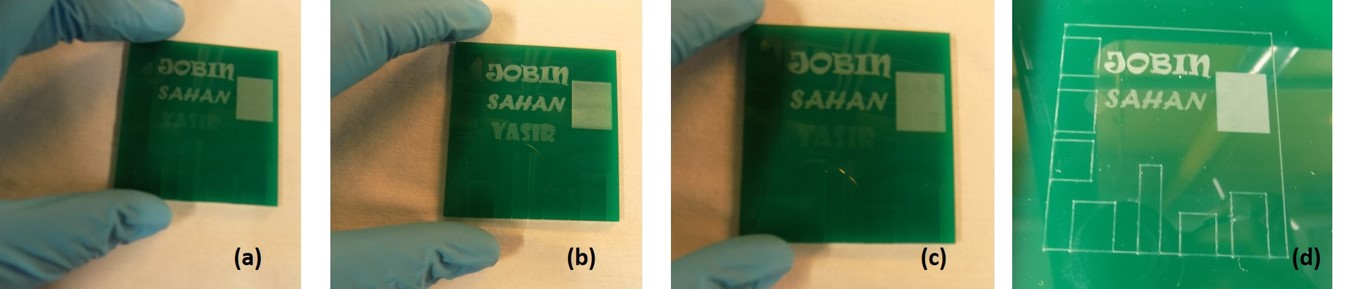
Below figure also shows the vinyl design transfer to RT duroid substrate using scotch tape.

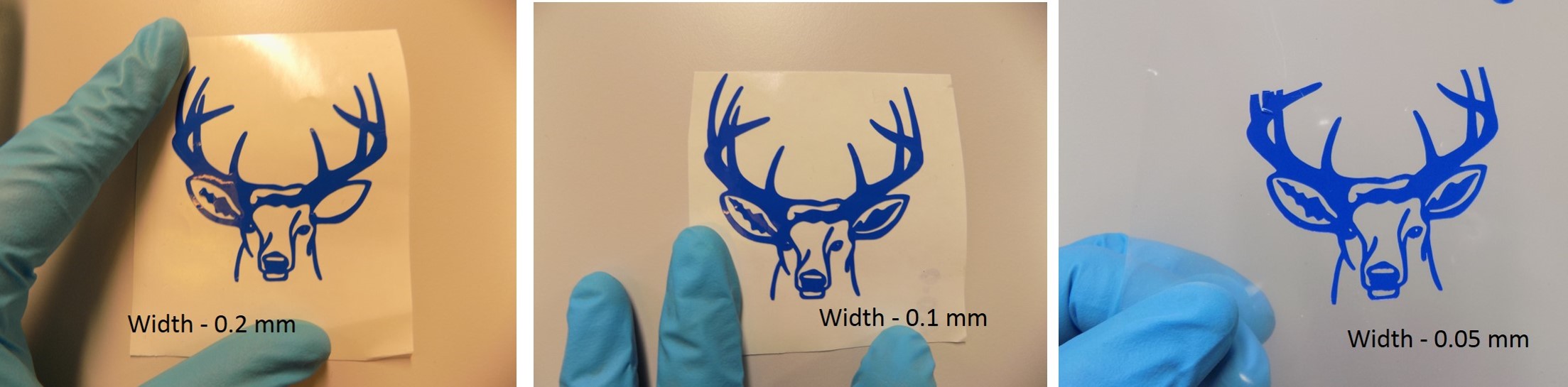
The complex design does not work well with the peel of the stage. I decided to repeat the complex design by changing the line width 0.2, 0.1 and 0.05. Figure 6 shows the vinyl cutter structure. Due to lack of experience, I destroy some part of my vinyl design. Still, it looks good, finally achieves to transfer one vinyl design to mylar film, as shown in the figure. It is also observed that with low linewidth, we can achieve more complex structures. The main problems faced during the vinyl cutter during peel off stage and vinyl cutter due to lack of experience.
Laser cutting and press fit design and fabrication
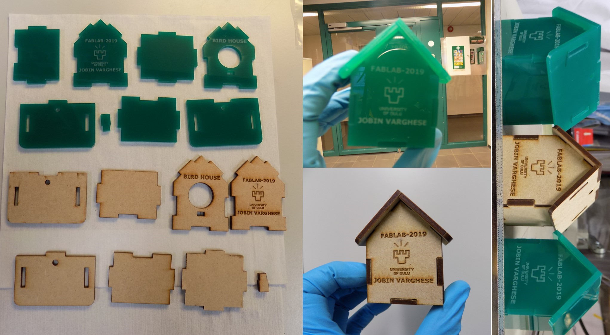
Press fit design and fabrication, I learn little more about laser cutting and Inkscape design. Based on my group assignment, I decided to use MDF and Acrylic board for my press fit. I decided to obtain a design from the internet and edit it in the Inkscape. A birdhouse design is chosen for my press-fit assignment — the design line width set as 0.02 mm. Detailed flow of work is shown in figure.
The acrylic birdhouse is repeated due to the misfit in the roof part of the design. I adjust the cutting speed lower, which improve my press-fit birdhouse. See my birdhouse made by press fit fabrication using laser cutting of MDF and Acrylic boards in figure.
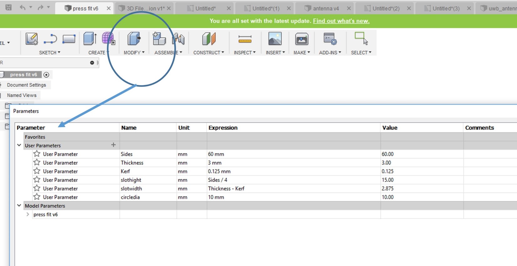
In addition to this, I also design a parametric model press-fit construction kit in Fusion 360. In Fusion 360, I first defined parameters (MODIFY-Change parameters-Add user parameters), I set a square of dimension sides 60 mm, material thickness defined as Thickness = 3 mm, Kerf = 0.125 mm, slothight = Sides/4, slotwidth=Thickness-Kerf, circledia=10mm (created circle in the design). The assigned parameters are shown below,
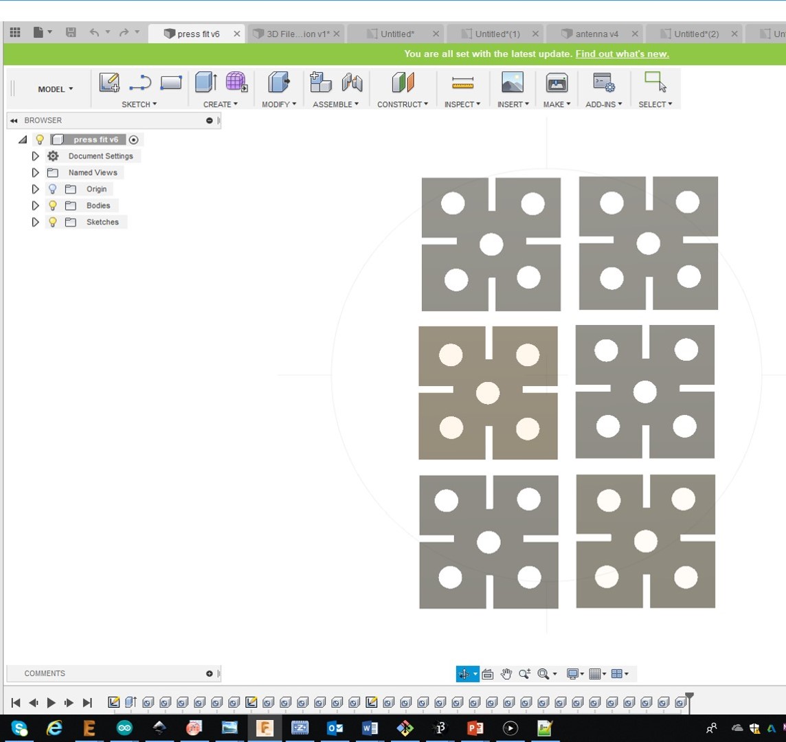
I draw a square and set the length of side from parametric design. Then, I seperatly design a rectangle with selecting slothight and slot width and duplicate extra 3 copies of the same and inserted in the slot area and trim it. Followed by extruded with parametric Thickness assigned. Then, I create a 4 holes as seen from the below design and set the hole diameter as circledia in the parametric design. Then, make extra 5 copies, these are shown below,
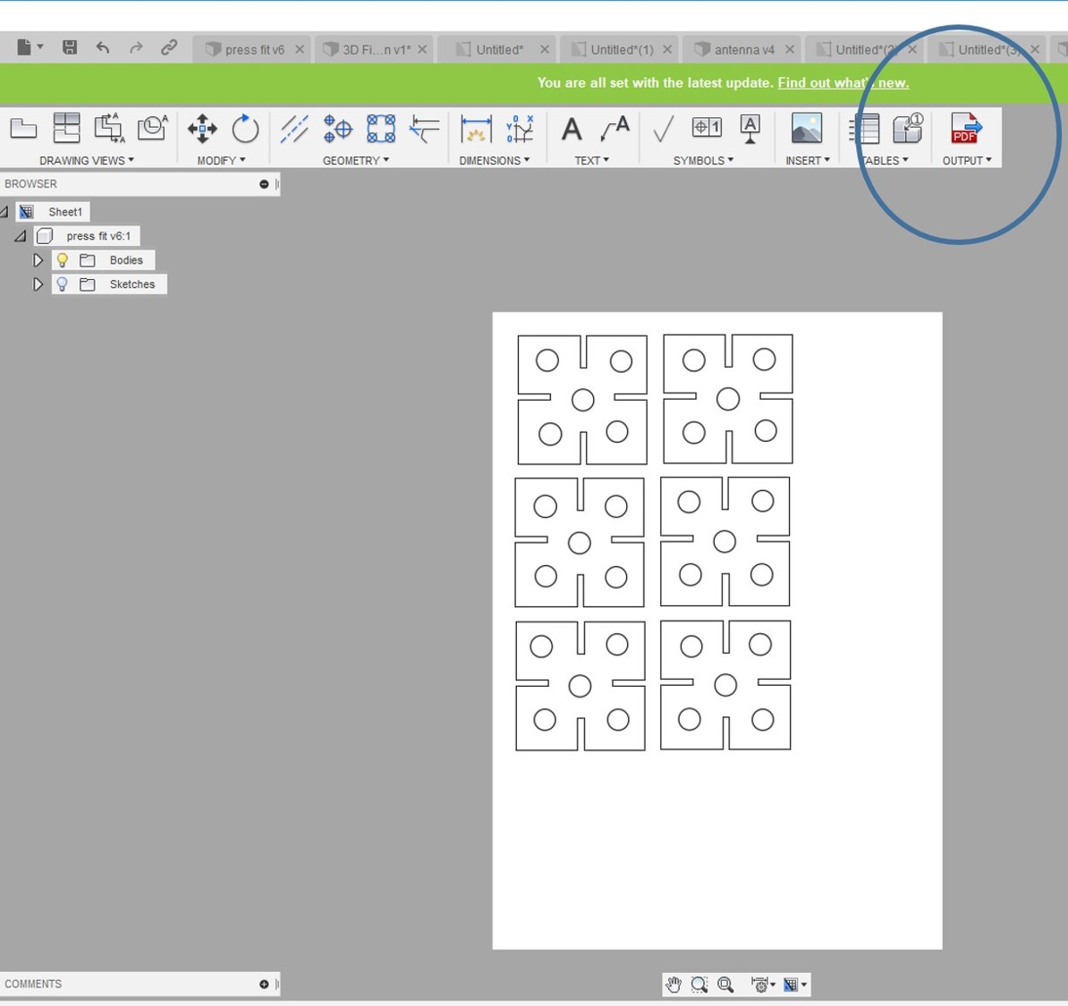
Furthermore, this design is saved as a PDF file by following steps MODEL-DRAWING-From Design, which open a window for choosing the sheet size A4. Followed by open another window, here I set scale 1:1 and click OK and Output as PDF file by set design only in the A4 paper selected. See the screenshot below,
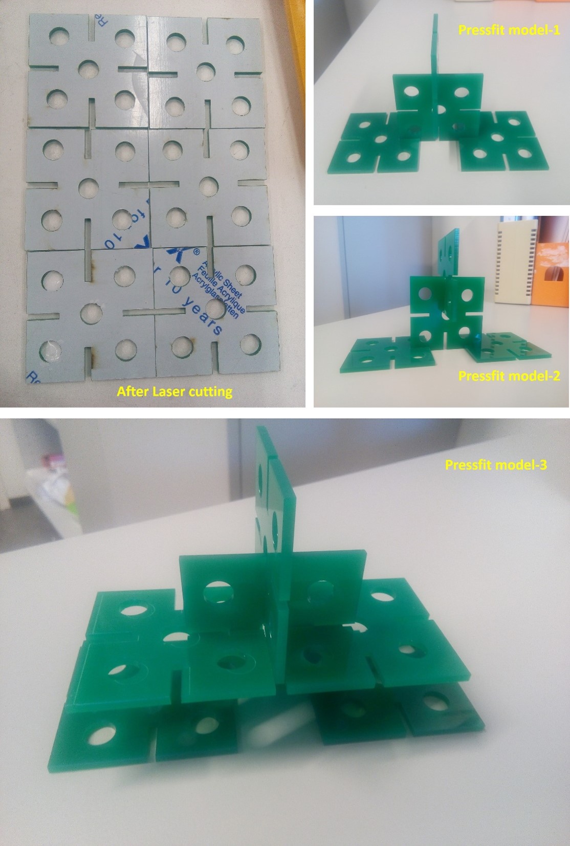
Further, the designed pdf file open in Inkscape to define the line width of 0.02 mm for all cutting lines and select the printer parameter for laser cutting. I follow the above-specified procedures used for laser cutting, and it cut everything successfully, Below figure shows the final press-fit construction kit.
Summary
Week04 assignments are beneficial for my final project. I have learned laser cutting, vinyl cutting how the characteristics influence the cutting. Effect of linewidth, on cutting and engraving the structures. I would like to practice more to get expertise in parametric design. Also, like to document the possible applications for Vinyl cutter and Laser cutter shortly.
Design files
- Birdhouse PDF file
- Birdhouse SVG file
- Reindeer Complex Structure PDF file
- Reindeer Complex Structure SVG file
- Reindeer Simple Structure SVG file
- Reindeer Simple Structure PDF file
- Group Work-2 SVG file
- Group Work-2 PDF file
- Pressfit F3D file
- Pressfit PDF file