Group Assignment: Electronics Production
In this week's group assignment the goal was to characterize the design rules for the PCB production process. To complete the assignment we designed three different boards, to figure out which settings are the best to use with our machine.
Printed Circuit Board
A Printed Circuit Board (PCB) is a board made for connecting electronic components together. It is made by combining different sheets of non-conductive material, such as fiberglass or plastic, that easily holds copper circuitry. The electronic components are soldered onto the PCB where appropriate. PCB is also known as printed wiring board (PWB) or etched wiring board (EWB). PCB's are found in nearly every electronic and computing device, including motherboards, network cards and graphics cards to internal circuitry found in hard/CD-ROM drives. There are different techniques that can be used to create a PCB. For example etching, sewing and miling. Furthermore there are also various materials that can be used to produce a PCB such as FR2, FR4, aluminium, paper or cardboard and even different kinds of textiles.
Creating the Eagle File
The creation of the files for milling is a real straight forward process. The software used for this task is Eagle. First we open Eagle and create a new project. Once the project is cerated we click the "add Part" button.

Into the searchinput of that we type "pad", to be able to see all of the Pads in the library.
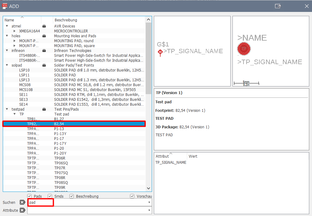
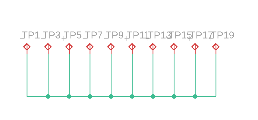
We then click on the pad we want and place it in the schematic by left-clicking (right-clicking rotates the part 90°). To connect the different pads, we utilize the "net" tool and connect them by left clicking.

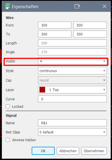
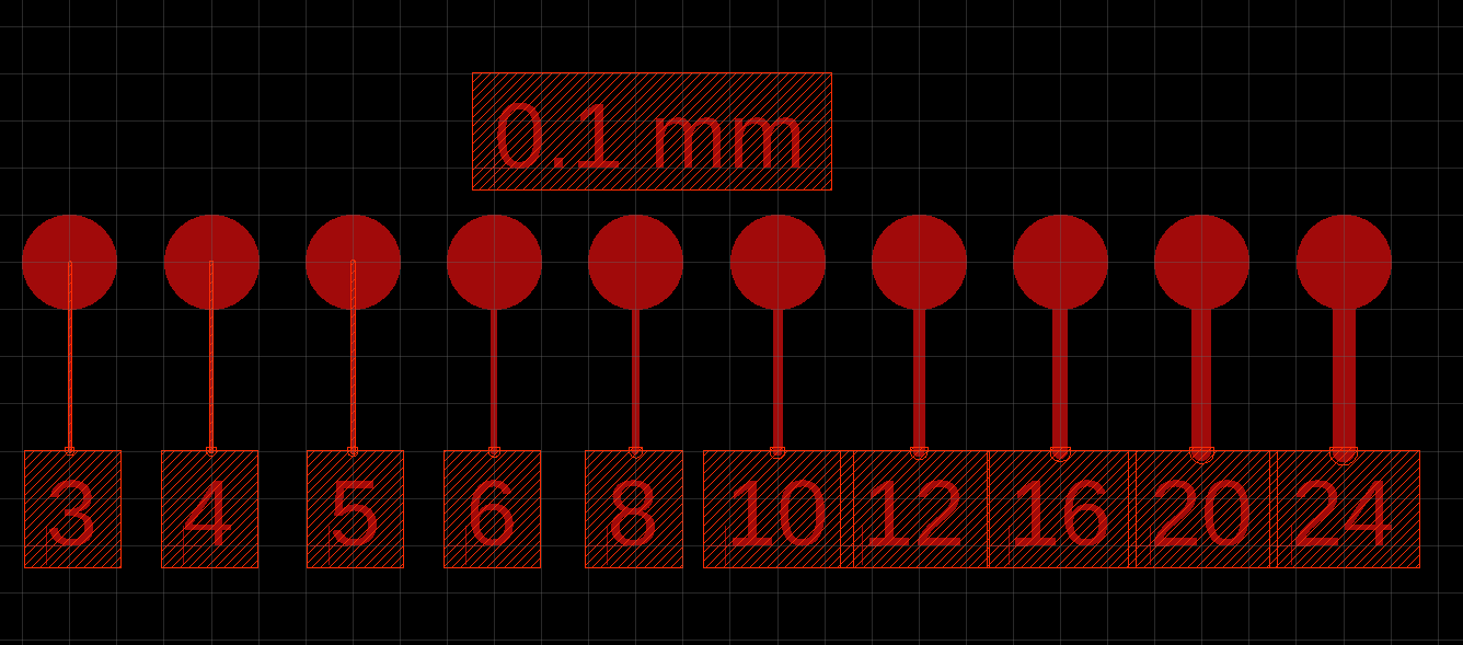
By clicking the board layout symbol in the top left corner, we can go into the board mode. There all of the components can be arranged as they will appear on the final board. They need to be connected via the "routing" tool. To now get differently sized traces we need to right-click the desired trace and modify its width property
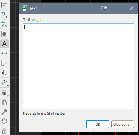
Now the only thing to do was to put in the text with the width if each trace. This is done using the "text" tool, by simply typing in the desired text and positioning it as needed.
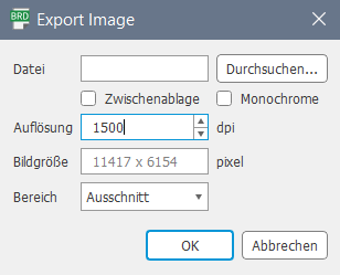
The finished board layout can now be exported as an image by clicking file > export > export as an image. Here we have to select a filename and a location, tick the monochrome box and change the dpi to 1500.
Using Fab Modules
Next we have to prepare the file for the CNC machine. To do that we use Fab Modules. This software is used to run any fab lab machine.
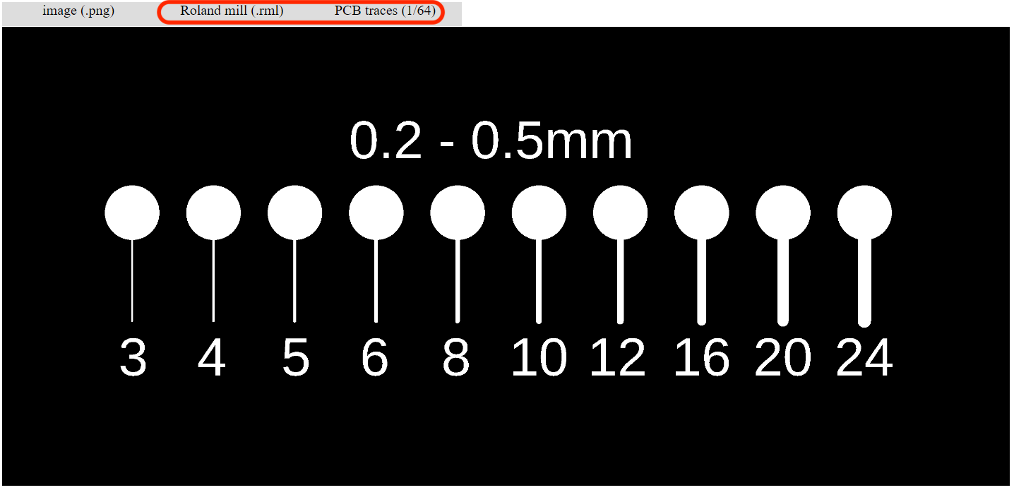
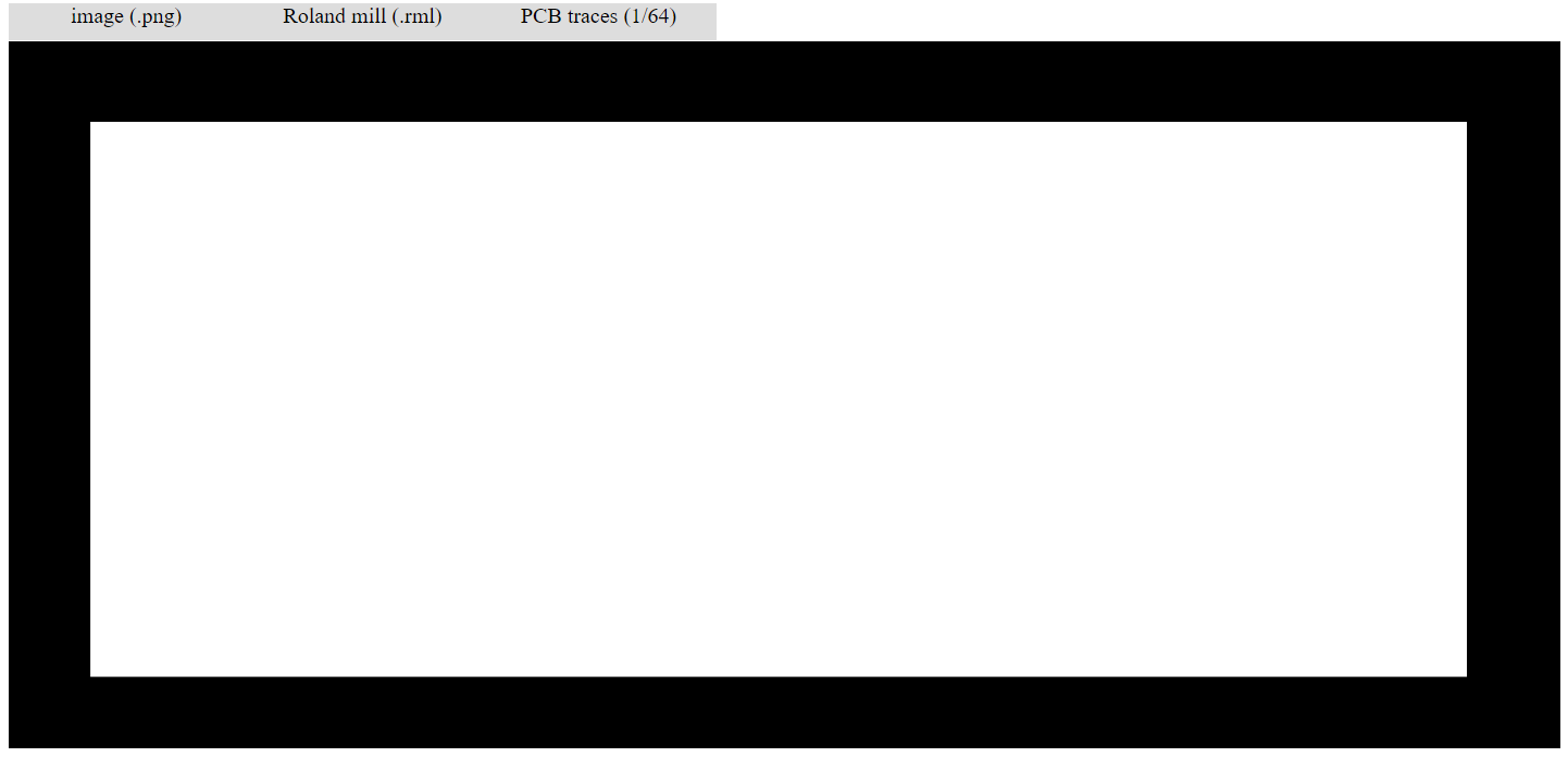
To create the milling traces for the CNC machine, we have to upload the PNG image on the Fab Modules Website. Then you have to choose the machine you are going to use, to produce the file in the format you need for the machine. Since we will be using the Roland Mill MDX-40, we select the Roland mill.
To mill the traces of a circuit board you will generally want to use the PCB traces 1/64.
Moreover select the right version of the machine. Since it's a MDX-40 I am going to use, I choose it as a setting.
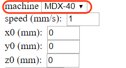
Now you need to set the following configurations to mill the traces:
After setting up the configurations, go to calculate. In order that the software can calculate the paths that the machine has to mill.
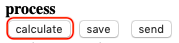
The image underneath shows the calculated version of the file. The blue lines display the path for the milling and the red lines represent the travel directions.
Next repeat the process to make the file for the cutout. Change these settings:

Repeat the process also for the other files.
CNC Machine
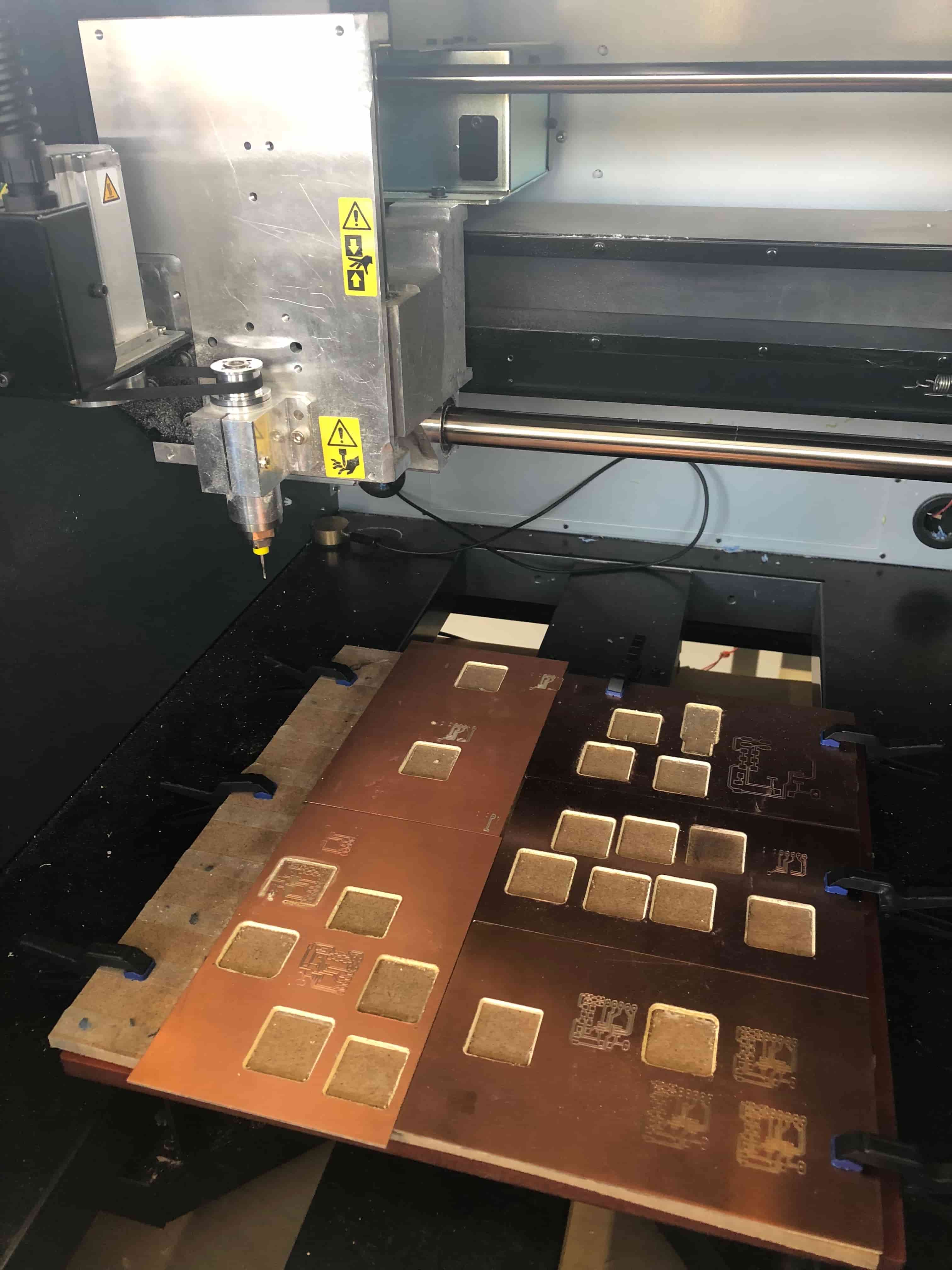
Below you can see the Roland Mill MDX-40 I used to complete the assignment. CNC milling is a specific form of computer numerical controlled machining. Milling is a process similar to both drilling and cutting. Like drilling, milling uses a rotating cylindrical cutting tool. The milling machine is able to move along multiple axes, such as the 3D printer. Most machines offer from 3 to 5 axes, providing performance along at least the X, Y and Z axes. Moreover almost any material can be used in a CNC machine. It really depends on the application. However, most CNC work with metal materials.
Using Roland Mill MDX-40
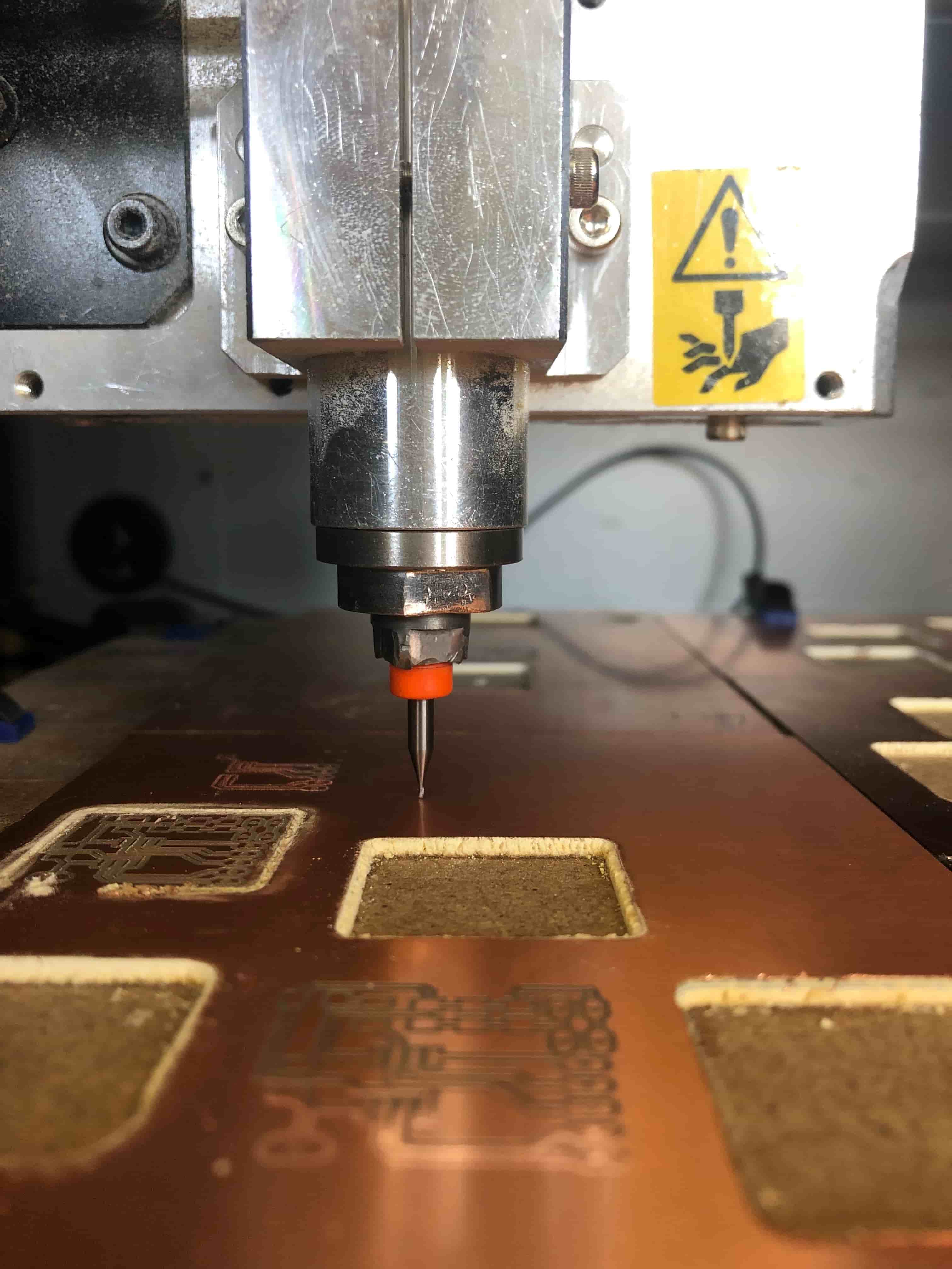
Before you start with the milling, it is very important that you attach the appropriate tool for the job. Furthermore you have to make sure, that the copper plate ist fixed on top of the milling area, so that it won't move. Also make sure that the plate is even, otherwise it may occur that not all the traces are going to be milled in same depth. Then start to move the tool to a place where you have enough space to mill the board.
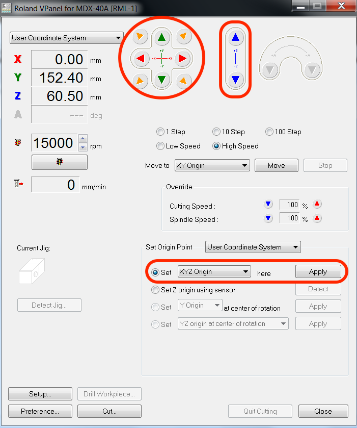
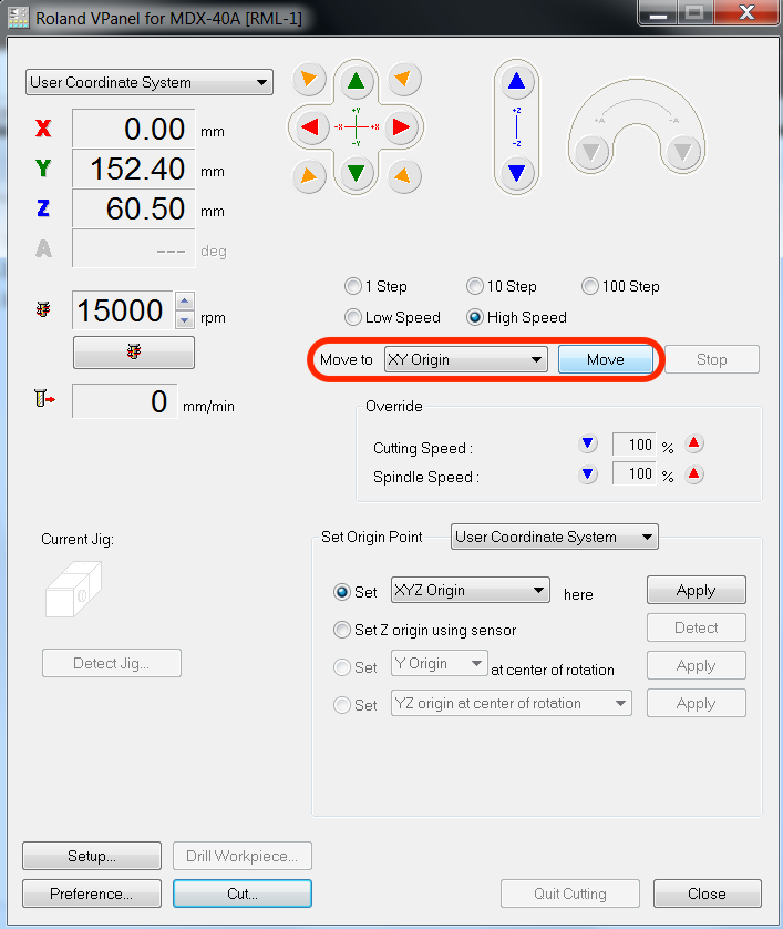
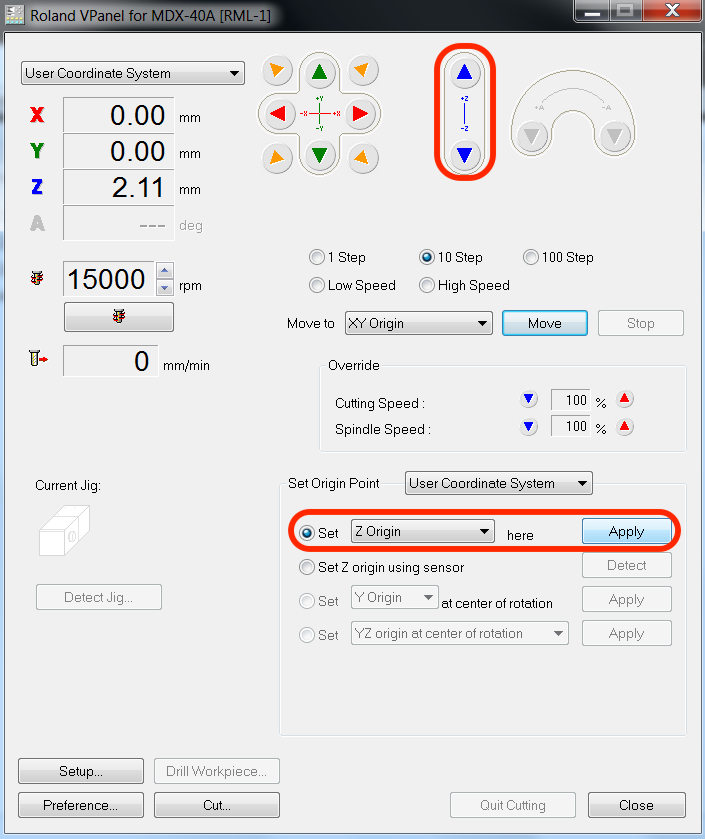
Underneath you can see the software that operates the machine. To move the machine in different directions use the arrows. In addition set the rpm to 15000. When you move the tool to set the z axis be aware that you could break the tool, if you go down fast using a high speed. To be sure that the tool touches briefly the copper surface, I used a multimeter, to check if there was a connection between the tool and the copper. Once the multimeter recognizes a connection click on the apply button and set the new origin.
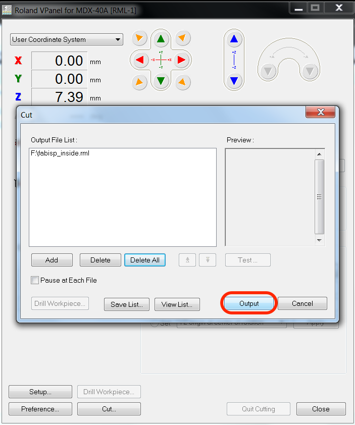
Next click on cut and delete all the current jobs that are shown in the output list. Then add a new job.
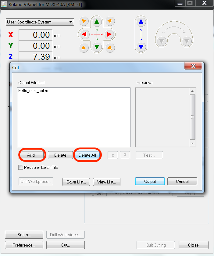
Now you only need to send the file to the machine.
To cut out the board we first need to change the tool by using two wrenches. Then we can move the machine to the previous set x and y point.
We need to set the z axis manually, otherwise the tool might break. As the cut is going to be deeper as before, the tool doesn't have to touch the surface precisely.
While the machine is creating the traces, make sure that the drawing of the curcuit is deep enough. Otherwise you have to stop the job and increase the depth. As soon as the job is done, clean the surface with the vacuum cleaner to get rid of the copper and the wood dust.
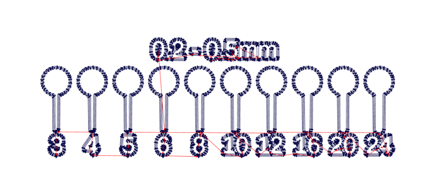
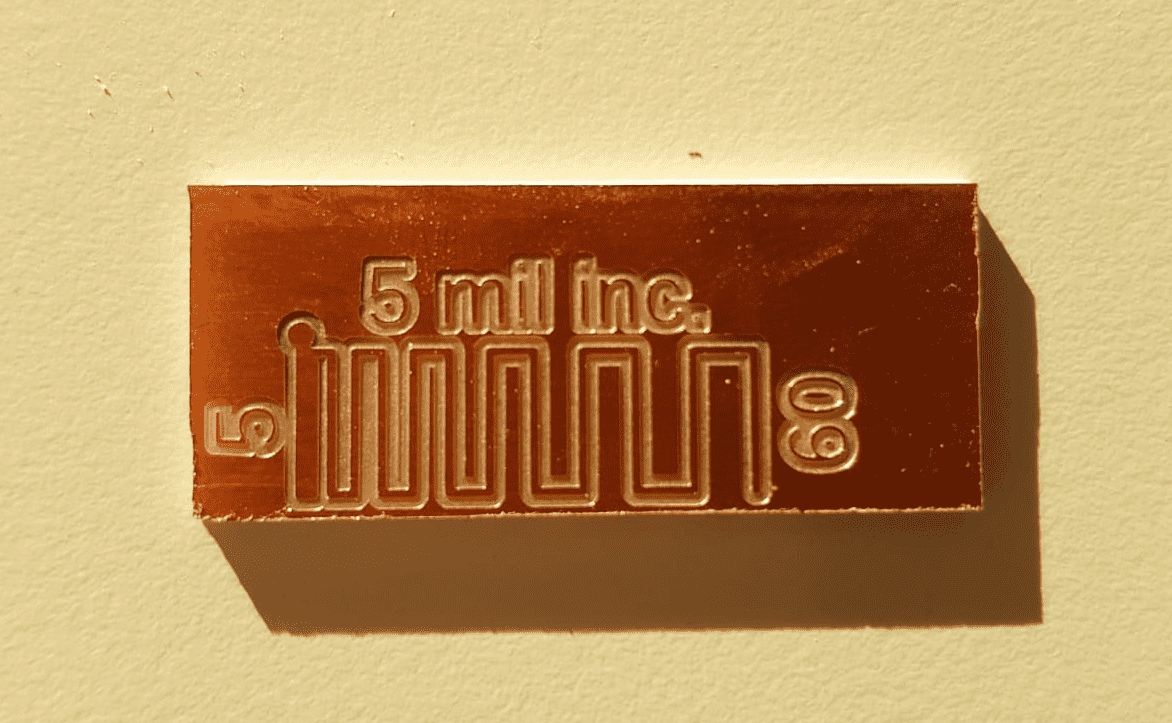
Milling dictance Test
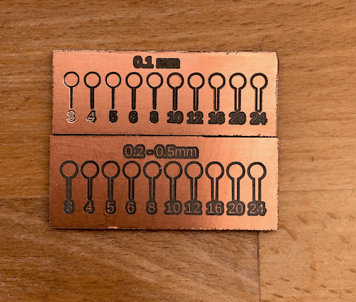
Another question, we asked ourselfes was, how much distance does a trace need in the milling process before it gets destroyed.So what we did was a snake type line with 5 mil distance increment after every turn. Our test makes clear, that every distance under 20 mil just won’t work with a drilling head of 0.2-0-5mm. Everything over 25 mil distance won’t be a problem for the milling machine.
Conclusion
All in all it gets clear that it is possible to do very fine traces without having a lot distance between. But also we have to think of other factors like for example the stability of the traces. Finer traces will make the soldering and further working harder. A broken trace could produce more work than it is to produce a board with wider traces. But with a little bit of experience you will get a feeling for what is possible and what isn't.