
Group Assignment: Computer Controlled Cutting
For this week's group assignment we had to characterize our laser cutter by making test part(s) with different cutting settings and dimensions.
Laser cutting techniques
Laser cutting is a technology that uses a laser to cut or engrave material based on computer-controlled parameters. The powerful and highly accurate laser focuses on a small area of the material. The laser can cut through different kinds of materials like: plastics, woods, rubbers, foams, papers, acrylics, fabrics and some even metal. With the laser cutter you have a total control of the beam of your laser when you use it. This means that you can control the beam heat output, the intensity of the beam on your material, and the duration of your beam. There are several techniques that can be performed with a laser cutter.
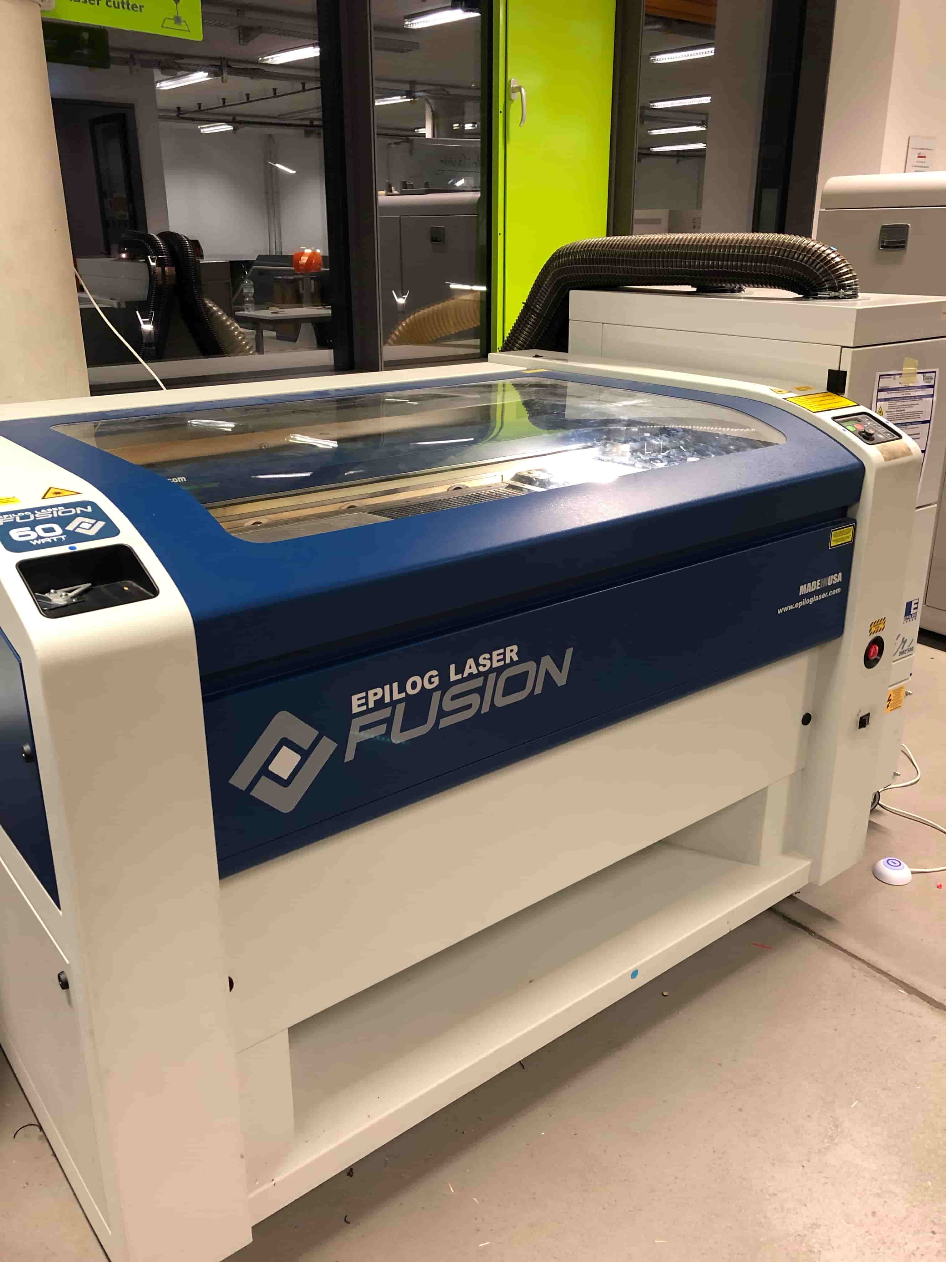
Using the Epilog Laser
Here some basic and very important rules that you have to follow, when you use this machine:
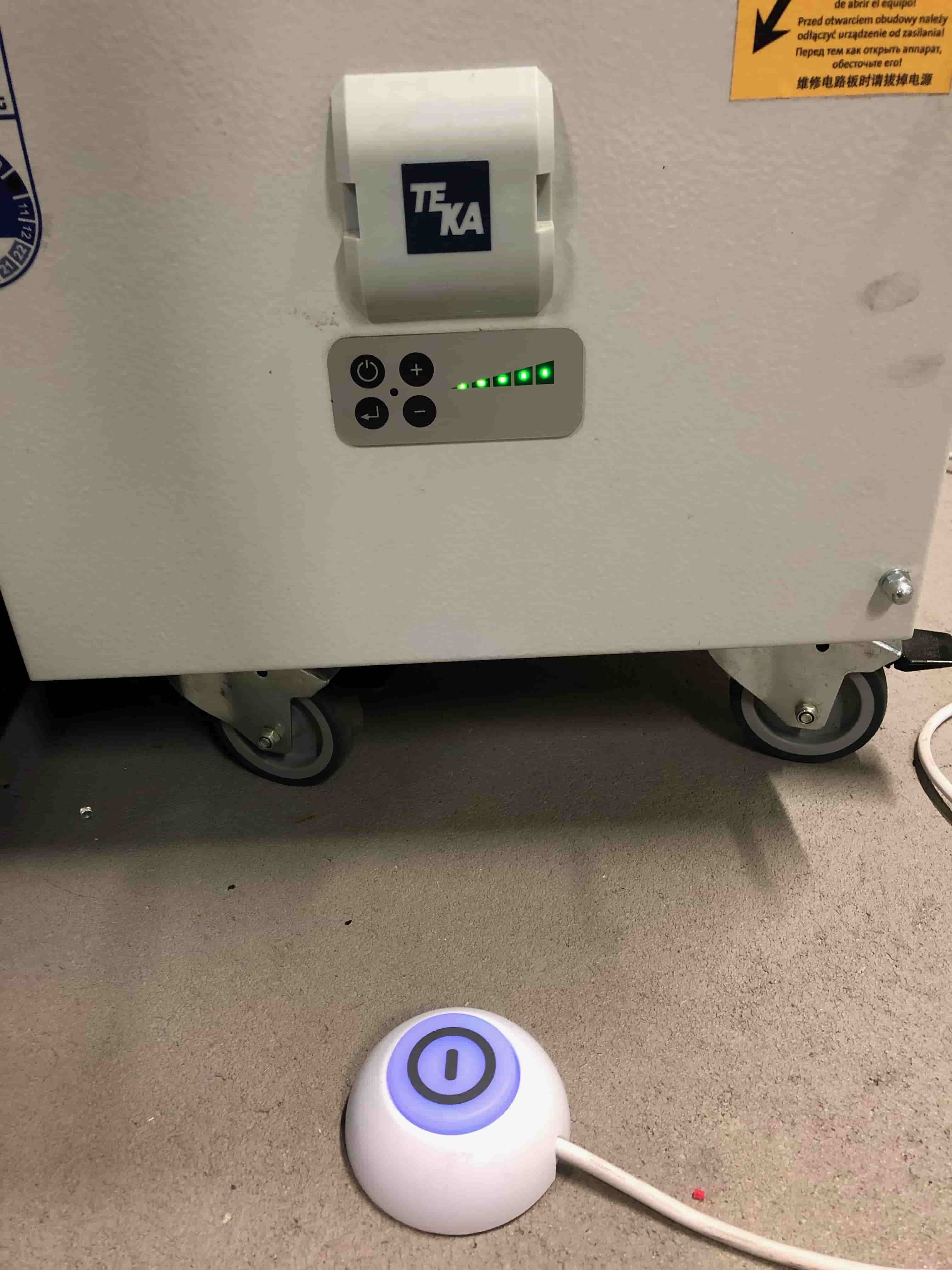
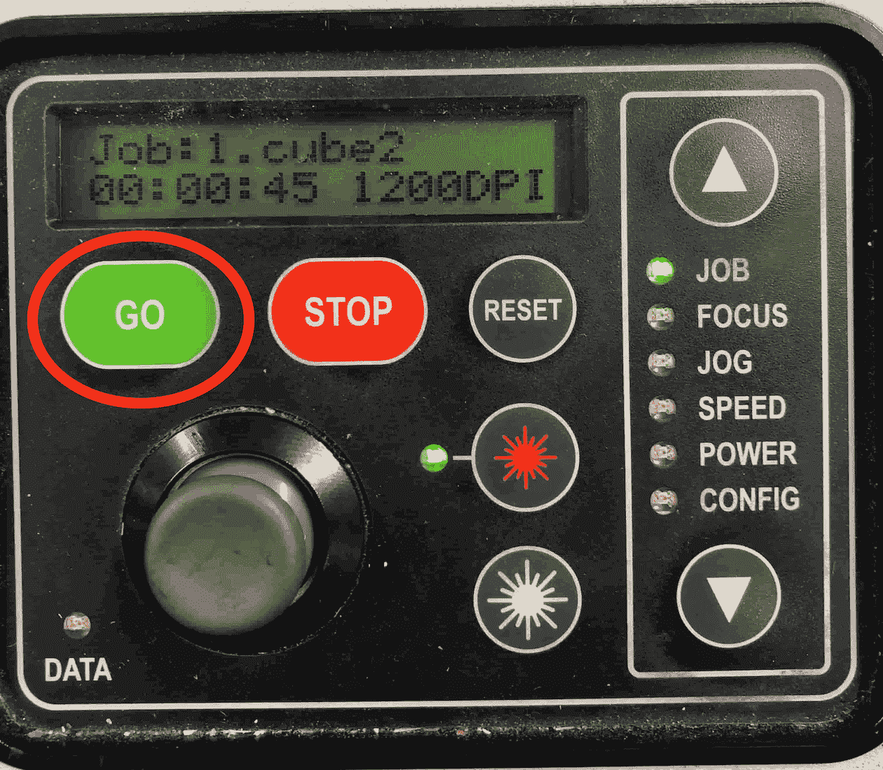
After we turn on the machine and the air compressor/filter, we have to set the focus and the jog. Select jog on the menu panel. Use the joystick to move the laser. To be able to see in which point the laser starts, push the (star) lightning button and a red laser pointer will show. After you moved to jog to the right position, confirm it by pushing the joystick.
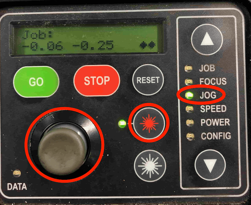
Now select focus on the menu panel. Use the joystick to move the surface. In addition use the triangle to measure the focus.
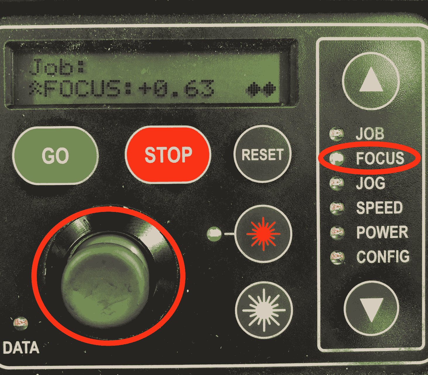
Hang the triangle on the designated place.
As soon as the top touches briefly the surface, confirm your settings by pushing on the joystick.
Since everything is set you can start the job. Morover on the display you can also see the duration of the job.
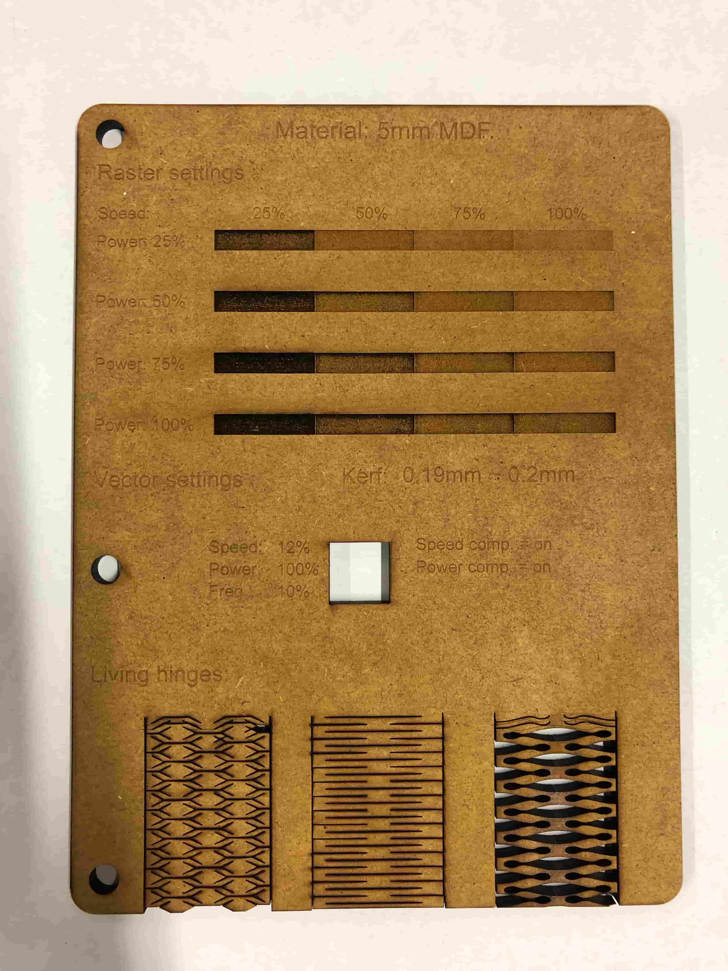
Desinging the Template
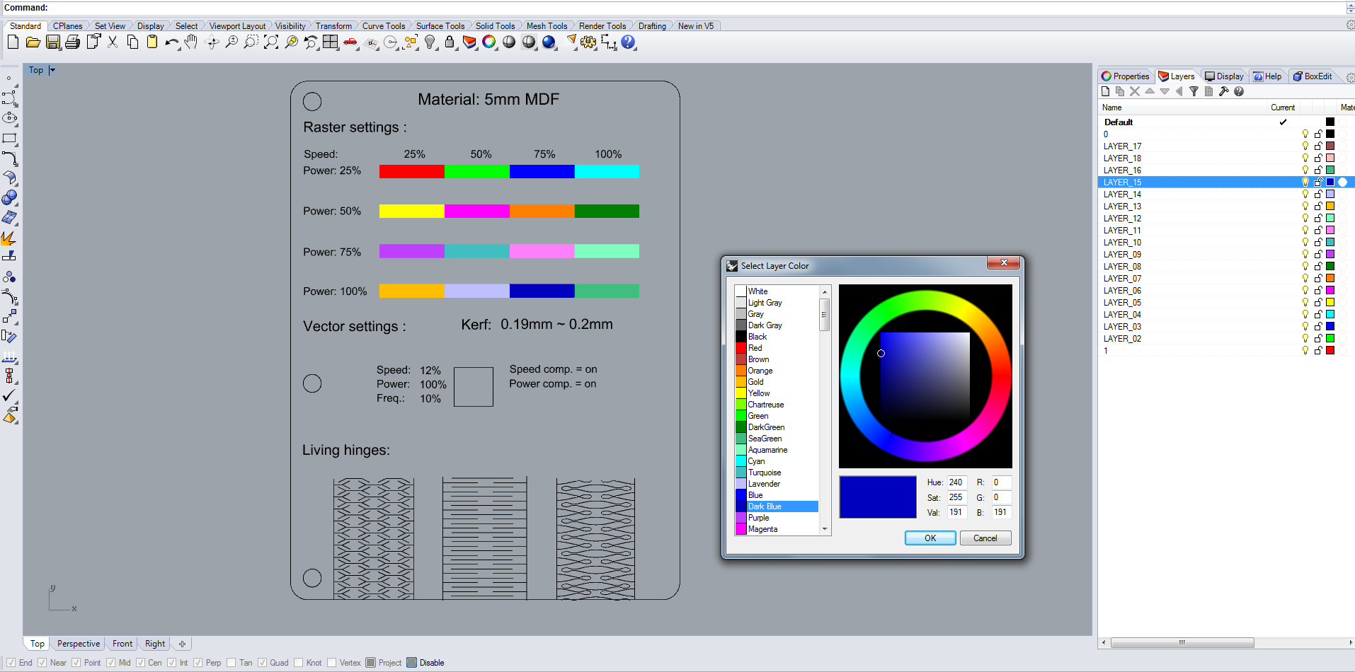
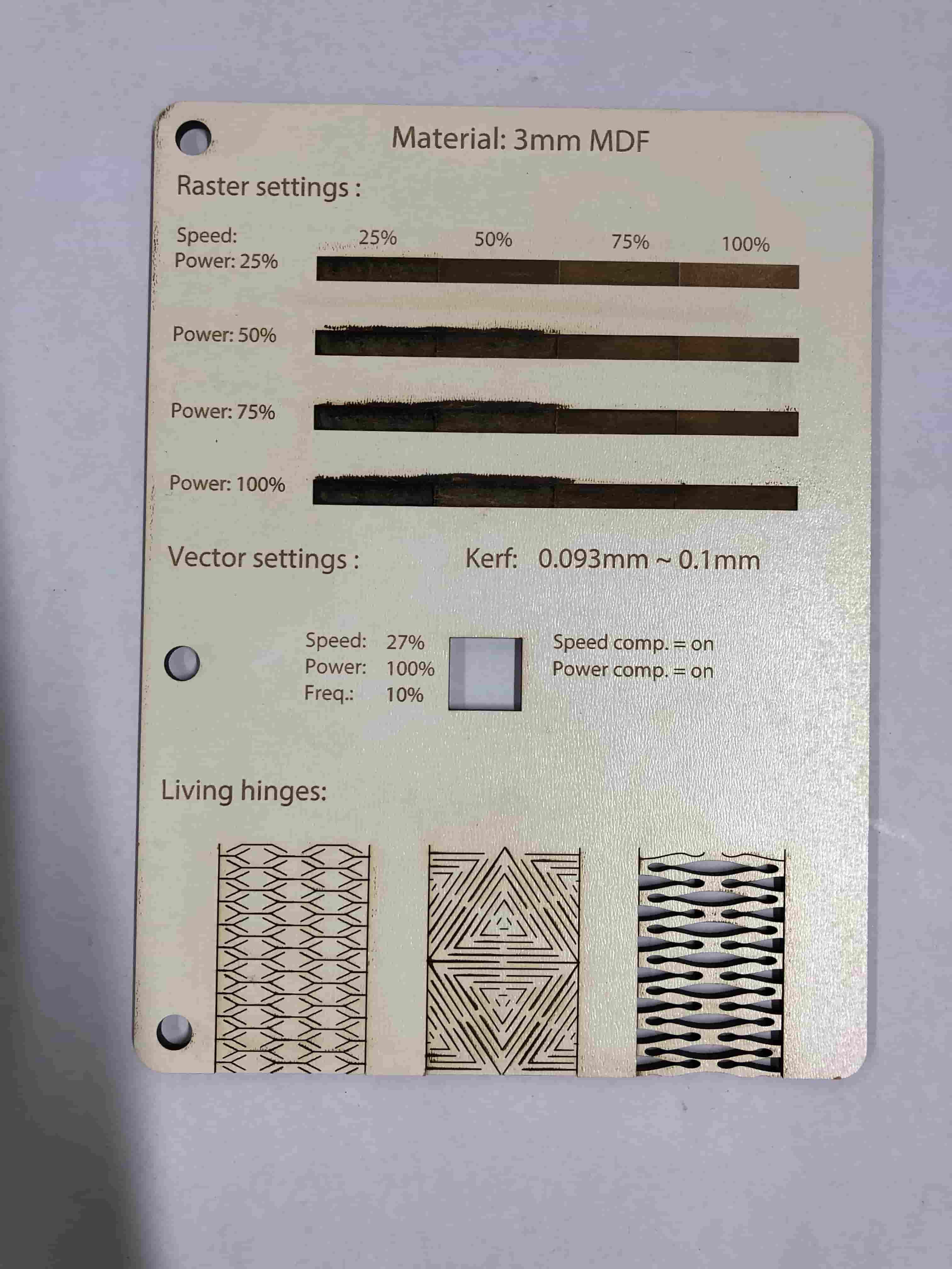
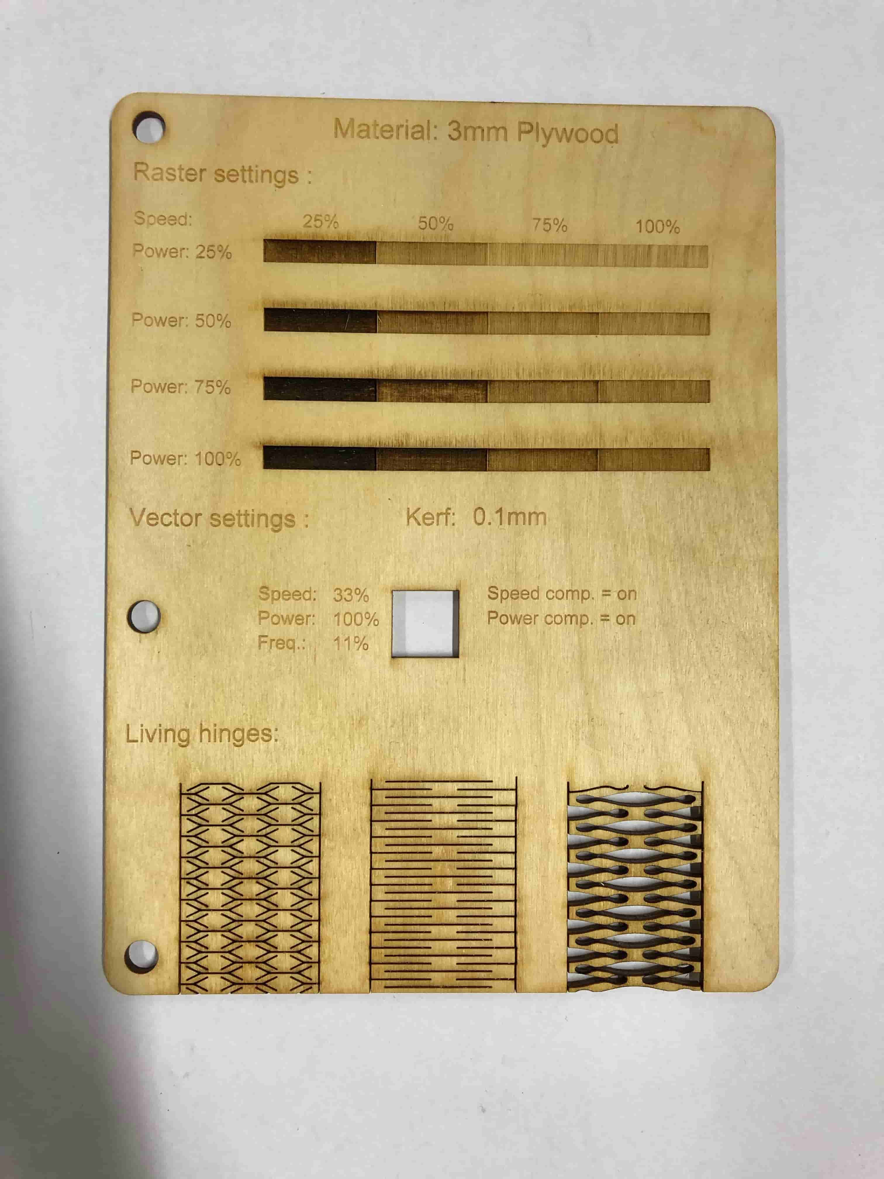
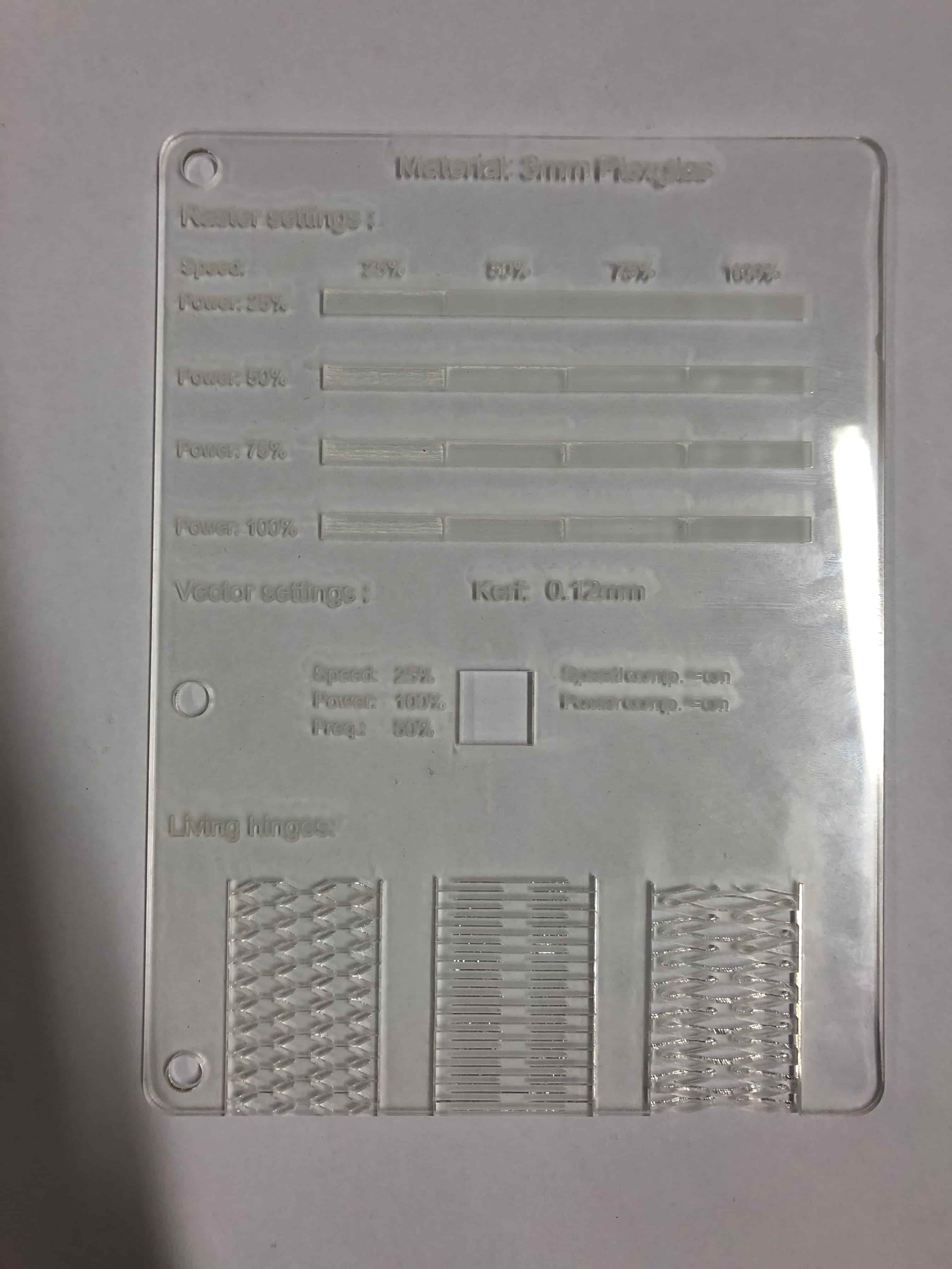
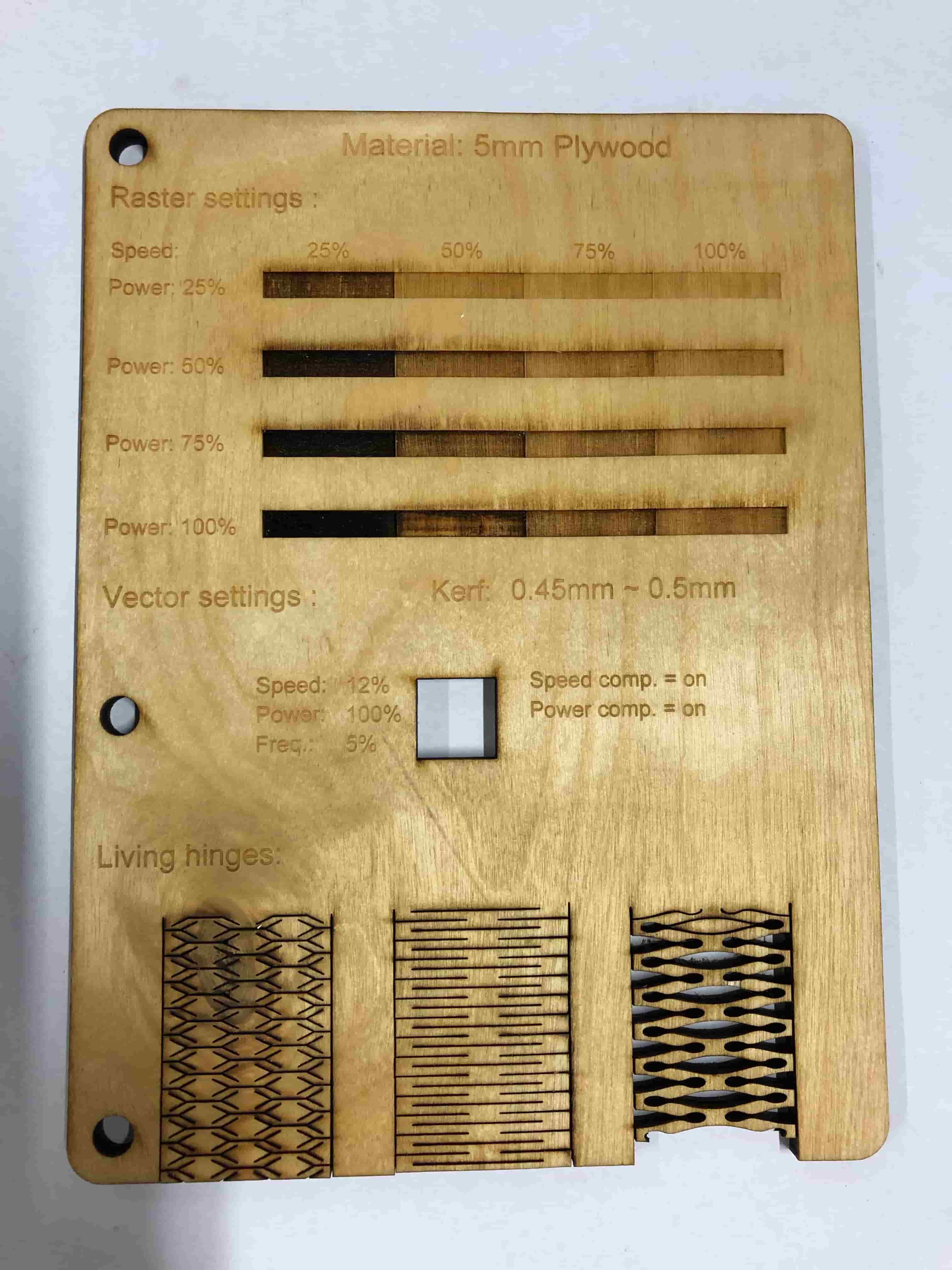
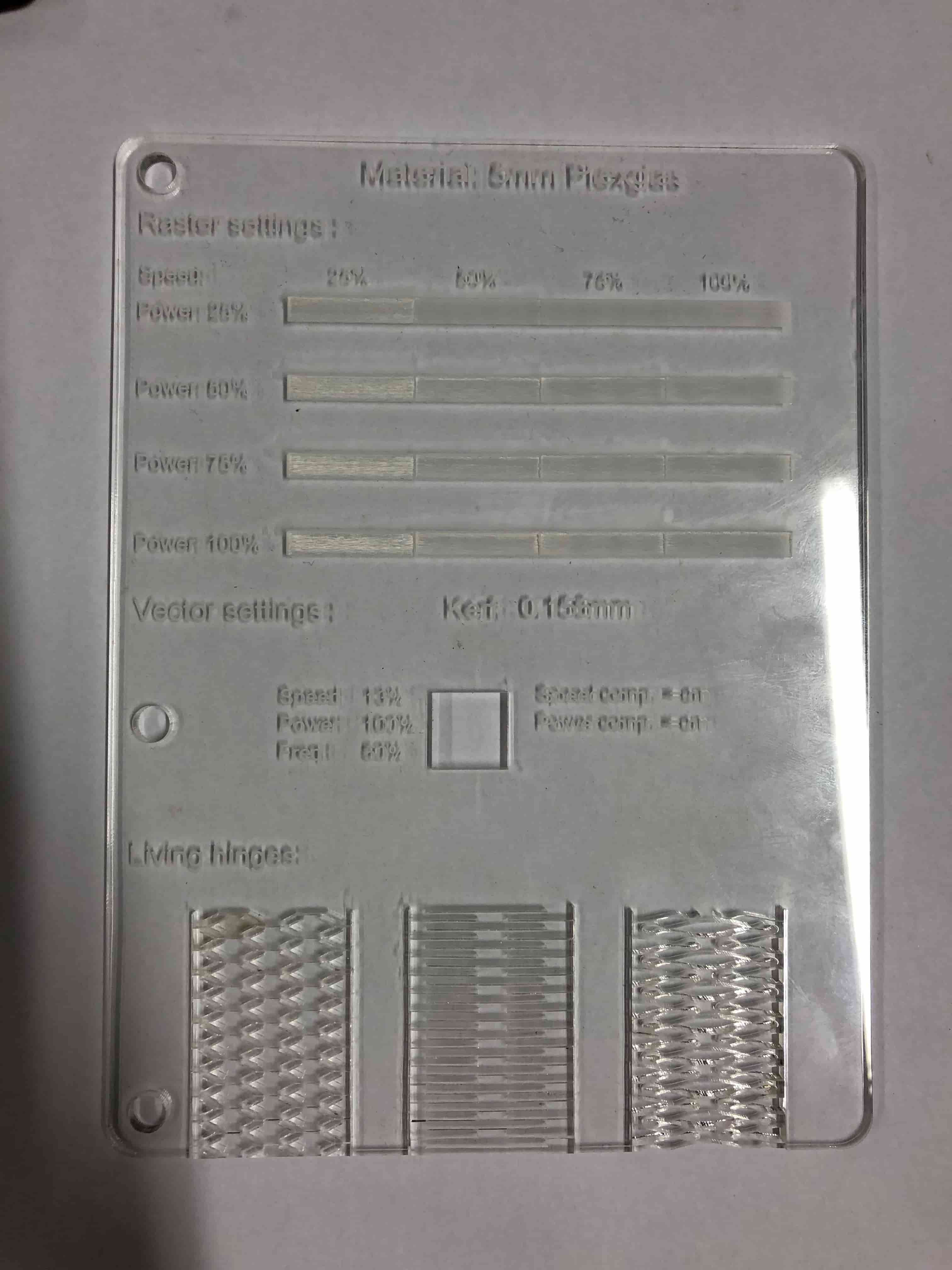
We decided to make little book with all of the settings for cutting, engraving, kerf and also living hinges in it. For that we created a template inside of Adobe Illustrator.
The creation was really simple, and we only used the most basic tools of Illustrator, being the Rectangle tool, the the line tool and also the text tool. The patterns for the living hinges were taken from instructables and just pasted and resized to fit the design. You can find the patterns here.
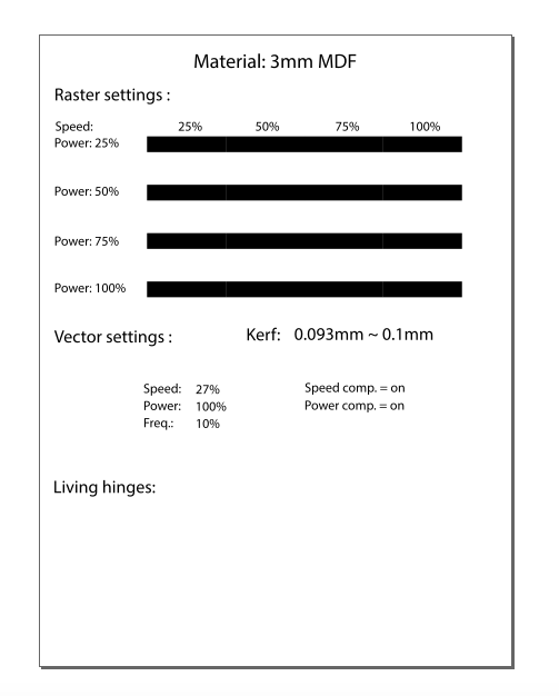
We made a grid of different engraving settings at the very top of the board, then we describe the kerf and optimal cutting setting. And after that there are three examples of living hinges, to see how the different materials react to different hinge patterns.
Sending a Job
To comunicate with the laser Cutter we used the software Rhinoceros, eventhough we used Adobe Illustrator to create the Files. We decided to use Rhino, because we already knew how to create different layers for the color mapping. But you could also use Adobe Illustrator to send the job.
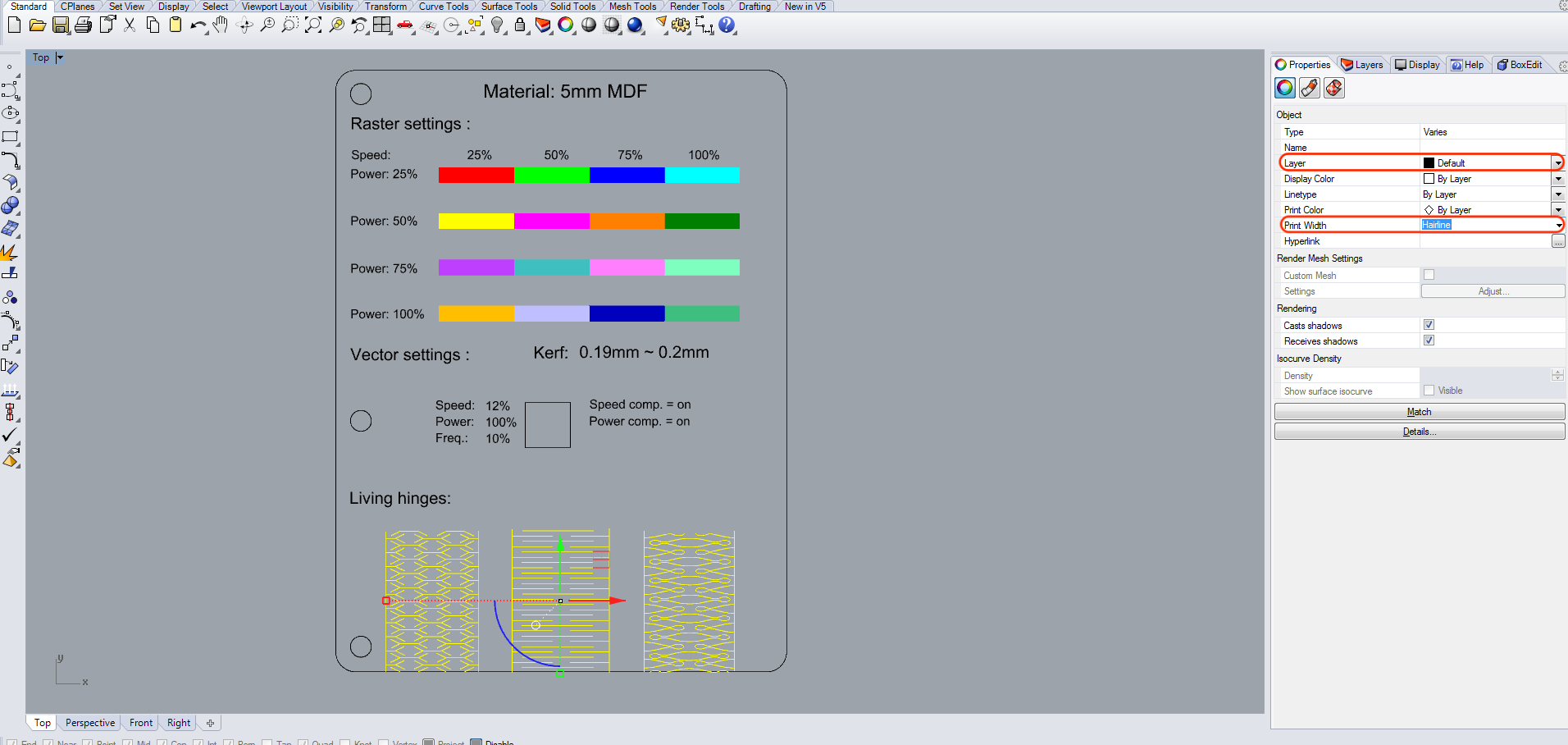
After importing the DXF File into Rhinoceros we have to create multiple layers with different colors for the engraving. We have to do this, because we use different settings for each engraving. The goal is to show the engraving behavior by changing the power and speed settings. We create the different layers to able to use Collor Mapping. Color Mapping performs two main functions:
For the handwriting that has also to be engraved you have to select the propper layer which would be the default, as these settings are going to be declared in the generel part.
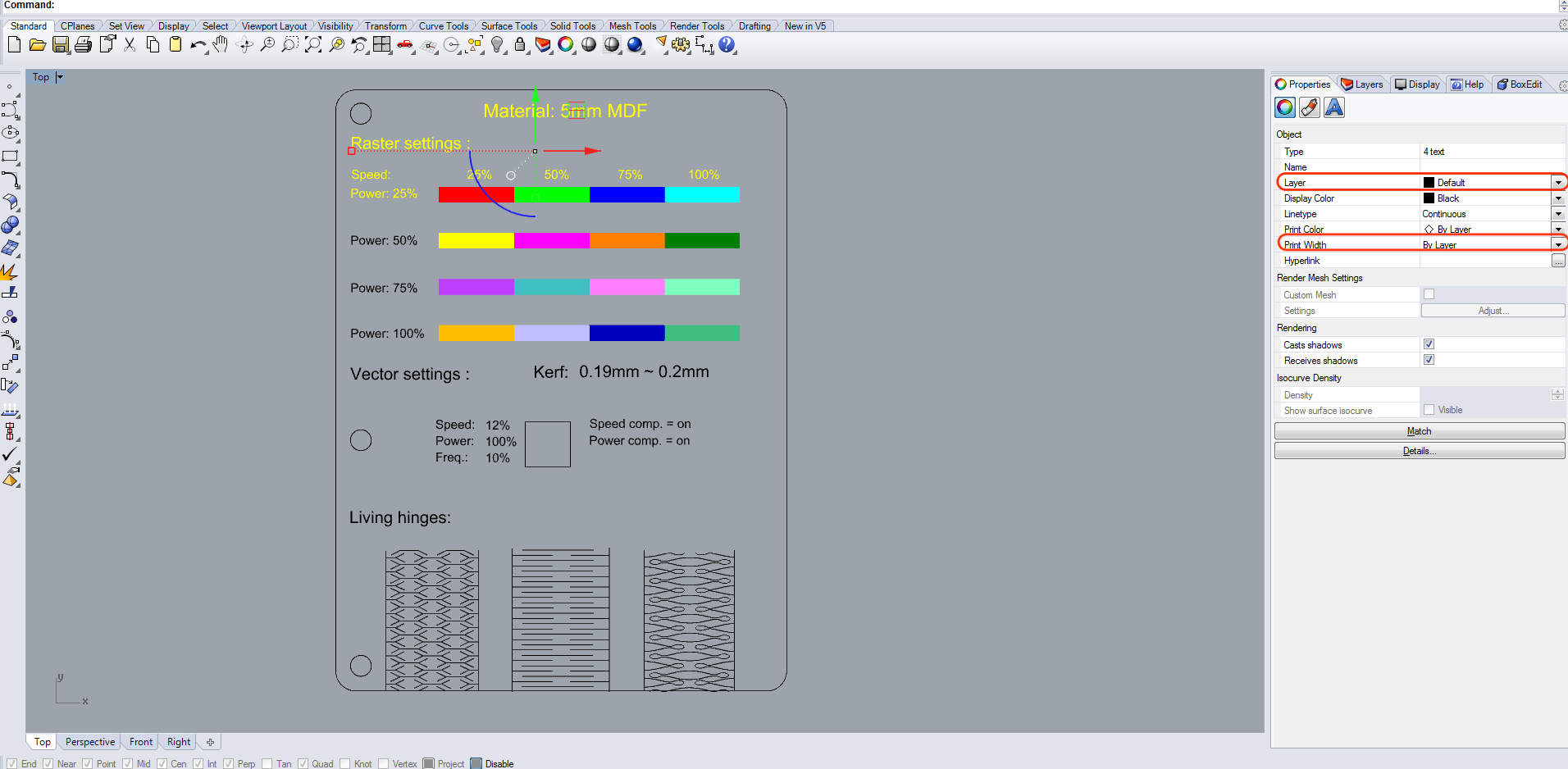
Everything we want to cut out, we have to select as harline.
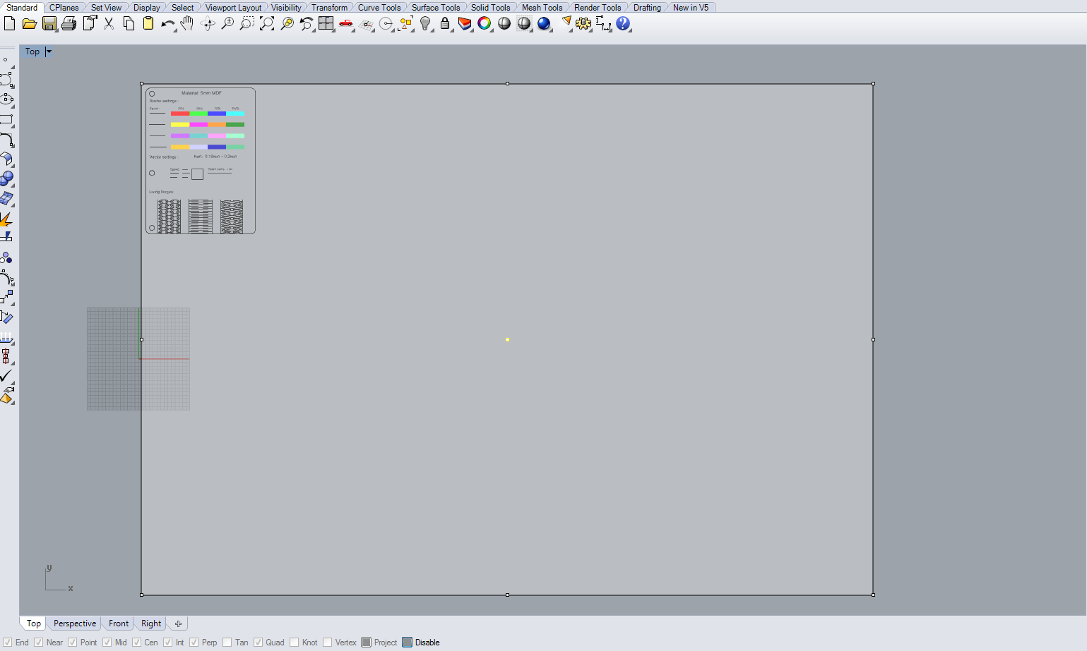
Now go to print and a new window will pop-up with the print settings. Here you first have to set the window, because start point of the laser is always the top left corner. So to do not waste a lot of material, make sure you set the window in the right spot.
Colormapping
To be able to make the grid for the engraving settings, we needed to utilize colormapping with the laser cutter. To get that to work, we opened the file in Rhino. Then we created a whole bunch of differently colored layers and assigned them to each individual block of the grid.Inside of the Epilog software we then needed to enable the colormapping and create a profile for each and every color we assigned beforehand.
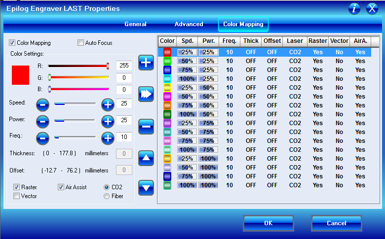
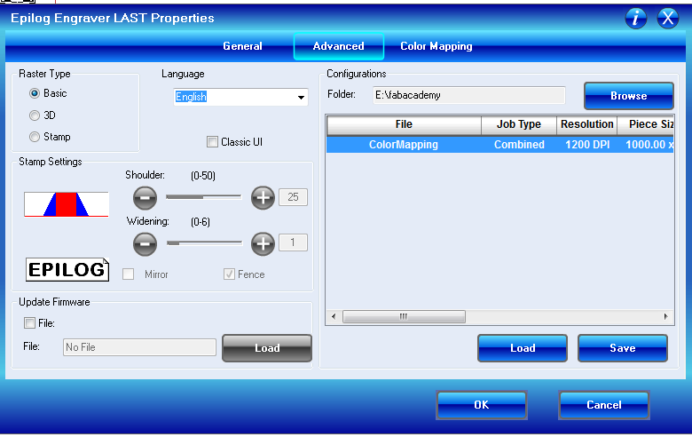
In the advanced tab we can then save and load this colormapping configuration, to not have to do it all over again when we restart the software. And also so everyone can just use it.
Finally just put the right settings for the material to engrave and cut in the general tab.

Vector Settings
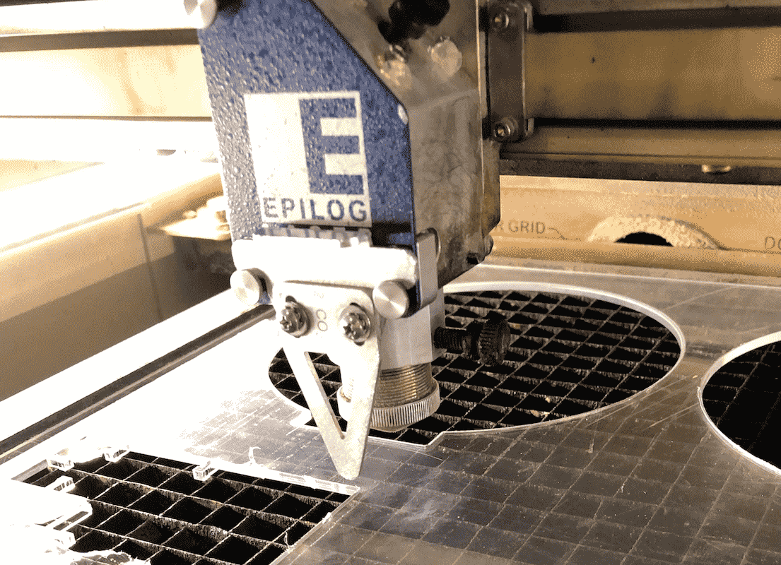
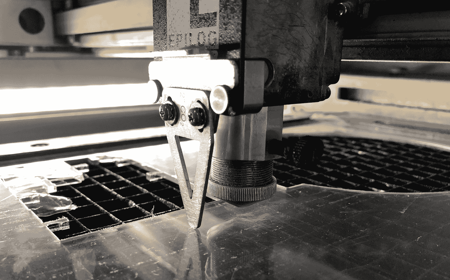
To find the perfect vector settings we had to start testing our laser cutter with different settings and on different materials. We`ve started with 3mm White MDF, and very high speed settings to try out what the laser cutter is capable of. The test was just simply a cirlce and a cube.
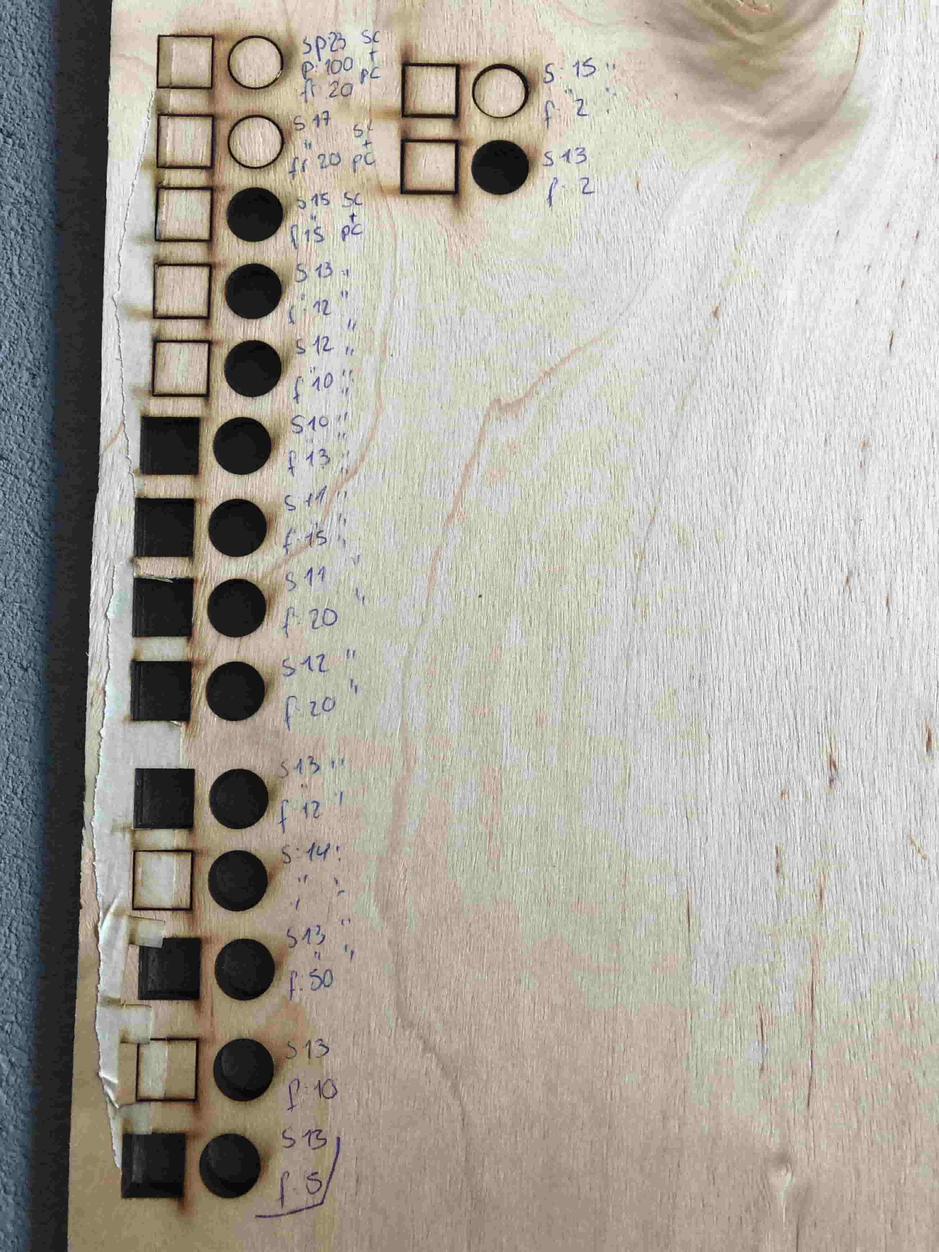
After trying out different speed,power, frequenzy combinations we have come to the perfect settings for each of our materials.
Kerf Test
We wanted to calculate the exact kerf of our laser cutter, so we did a small test after a self made template.
Now we have a frame and 8 identical cut pieces. The formula is very simple the width of the 8 pieces (71,2) minus the border of the inner frame (72) divided by 8. The result is 0,989 = 0,1mm.
Cut
Download Files
Collor Mapping Advanced-File
Color MappingSVG-File
Template
DXF-Files
Epilog Settings BookTemplate