15. Mechanical design
Assignment
- Group assignment
Design a machine (mechanism + actuation + automation), including the end effector, build the passive parts and operate it manually.
Group Assignment
End Effector Design
Research
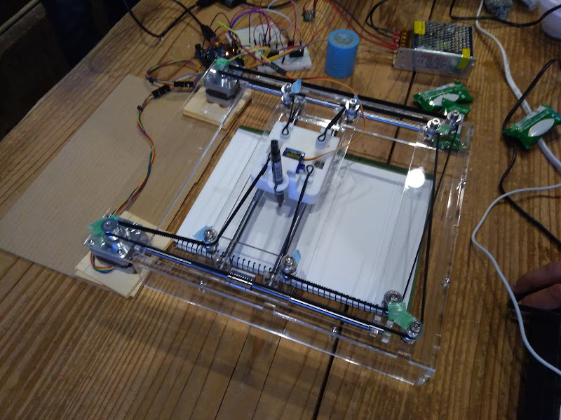
First I researched the end effector of following coreXY projects. They attaches a kind of pen and lift it up with a servo motor.

Planning
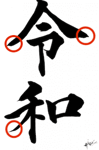
I planned to design the end tools to hold ‘Fude’, brush of Japanese calligraphy.
One of the important technique is to sweep and lift the brush gradually. (see red circle below).
So the requirement of the design is :
- Mechanism to hold Fude while moving and writing
- Mechanism to control z-motion, lift Fude gradually
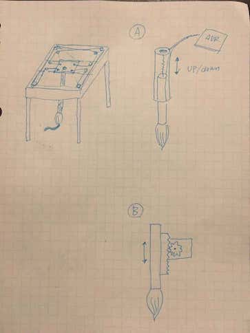
I sketched two types of mechanisms and did rapid prototyping.
A) Fiber actuator type (Artificial muscle )
B) Rack & Pinion type
Fiber Actuator type
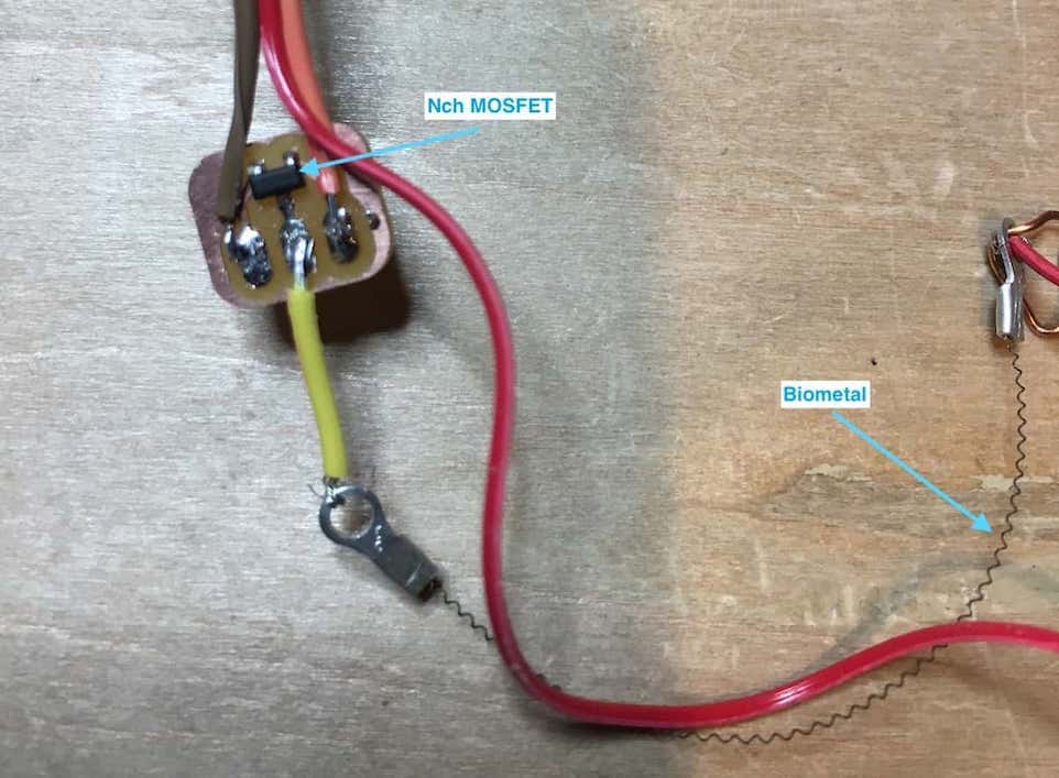
I planned to use Biometal. It is a fiber-like actuator based on shape-memory alloy, and moves like a muscle when current flows.
 ..
.. 
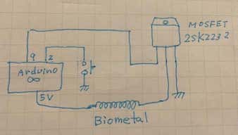
The circuit of the biometal is very simple. The biometal is connected between Vcc and drain of Nch-MOSFET, and the gate is connected to the analogue out of Arduino. The biometal shrinks according to the value of pwm, but the movement is not so big.
First I tested the circuit using Bread board, Arduino and Nch MOSFET 2SK2232 that I have.
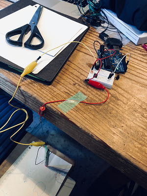
- video
The pen lifted when the tact switch was pressed.
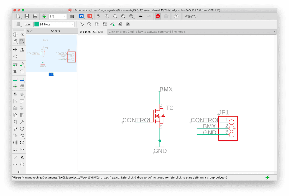
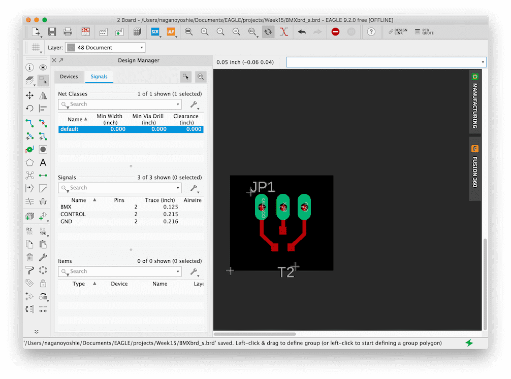
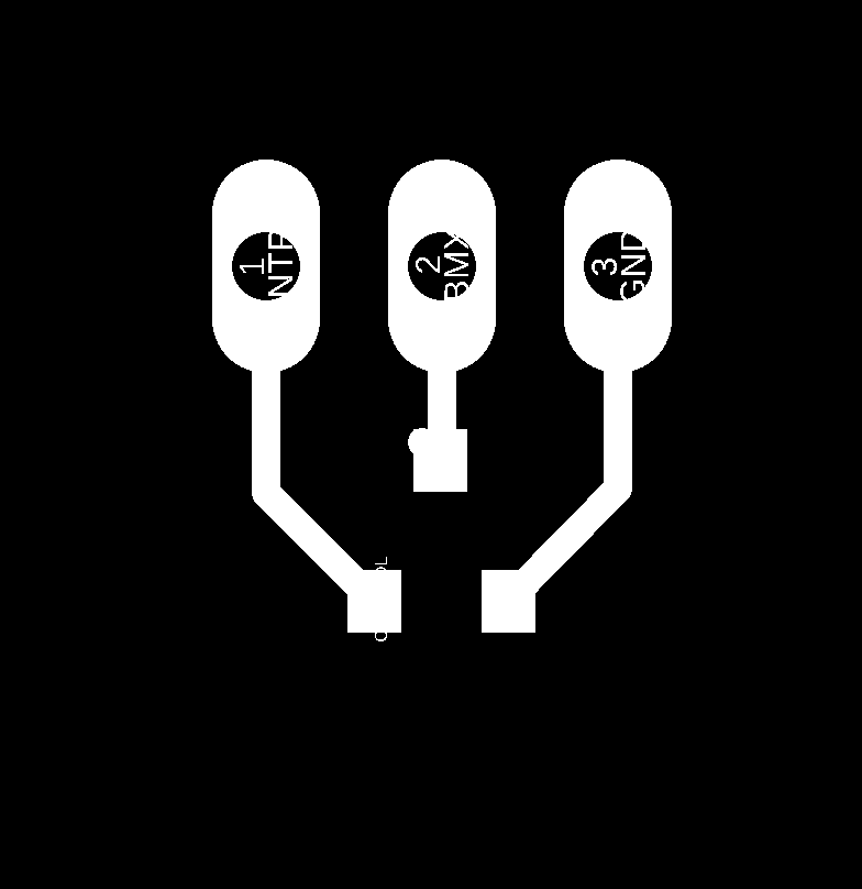
- Board design
As I confirmed the movement of the Biometal, I designed the board using Fab inventory.
Parts List
| parts | description | number |
|---|---|---|
| micro controller | Arduino | 1 |
| Biometal | BMX150 | 2cm |
| MOSFET | NDS355ANCT-ND | 1 |
-
Eagle design
-
Mods
- Difference of the movement by pwm value
PWM value = 75
PWM value = 150
- Set the mechanism in the bamboo enclosure
- Arduino Code
//--------------------------------------------------
//     Endtool Trial : BMX
//--------------------------------------------------
const int analogOutPin = 9;
const int buttonPin = 2;
int buttonState = 0;

int maxVal=150;

void setup() {
  pinMode(buttonPin, INPUT_PULLUP);
 Serial.begin(9600);
}

void loop() {

 buttonState = digitalRead(buttonPin);
 if(buttonState == LOW){
   analogWrite(analogOutPin, maxVal);
    Serial.println("pushed");
    delay(100);
 }else{
    analogWrite(analogOutPin, 0);
    Serial.println("High");
    delay(100);
 }
}
Fude Holder#2
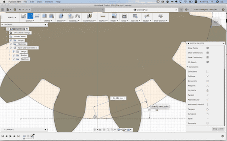
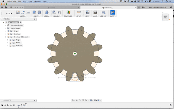
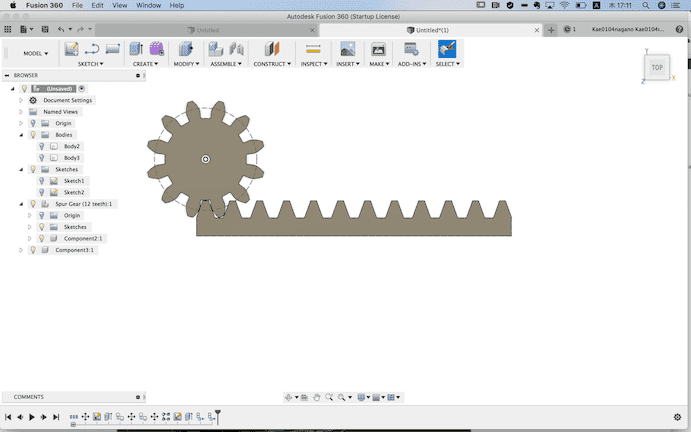
Referring to this tutorial, I designed the rack and pinion mechanism.
- Fusion 360 Rack and Pinion Tutorial
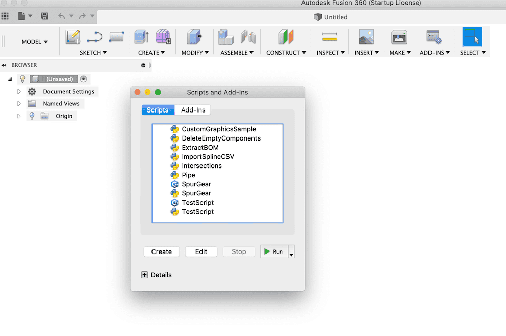
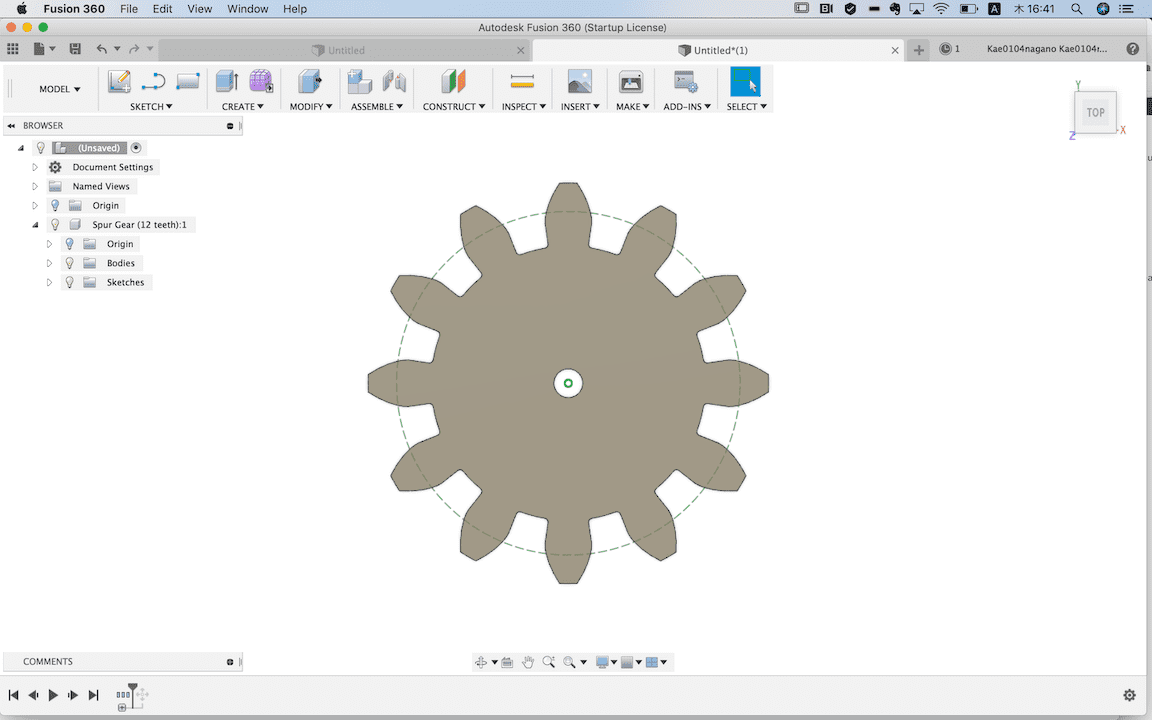
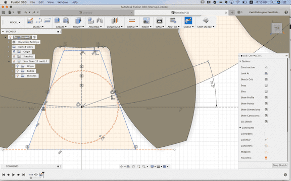
Select ‘ SpurGear’ from Add-Ins menu.
I chose 12 for the number of Teeth.
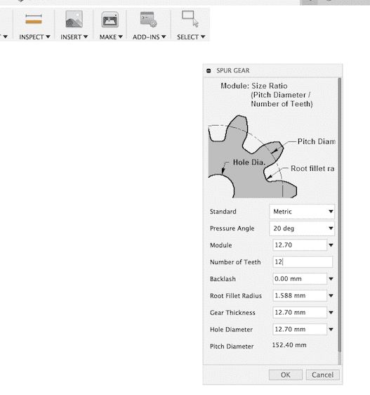
Pinion was created automatically.
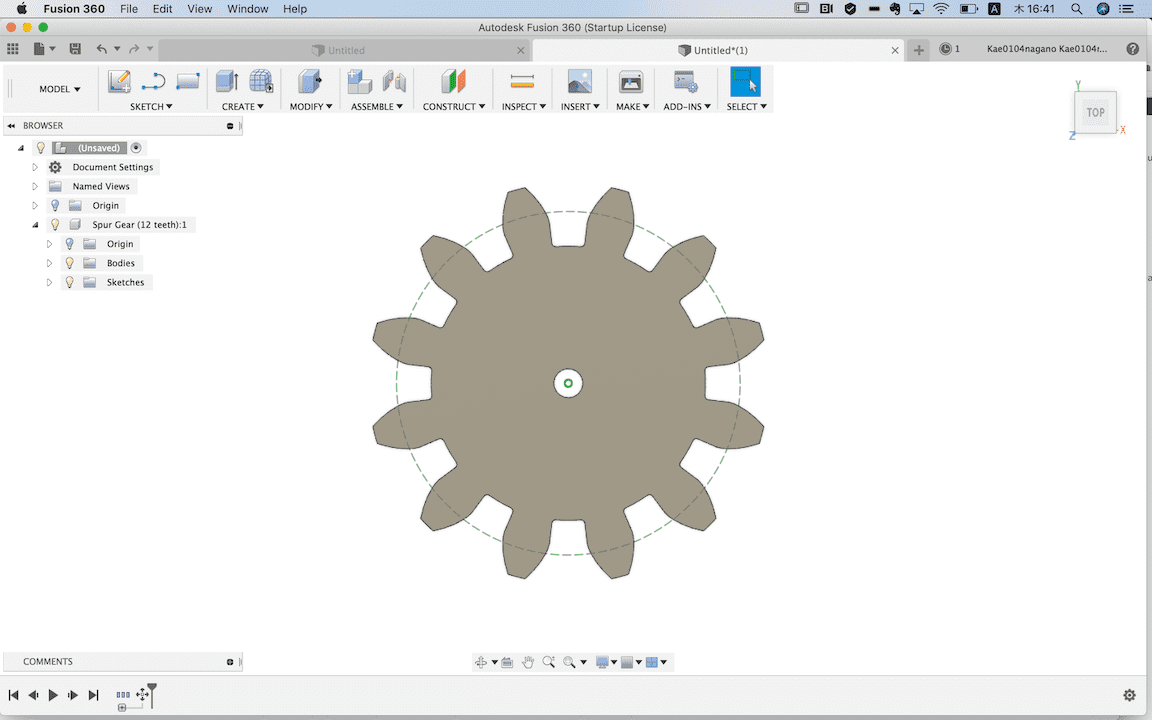
Rotate the pinion 15 degrees (= 180/12) in preparation for designing the Rack.
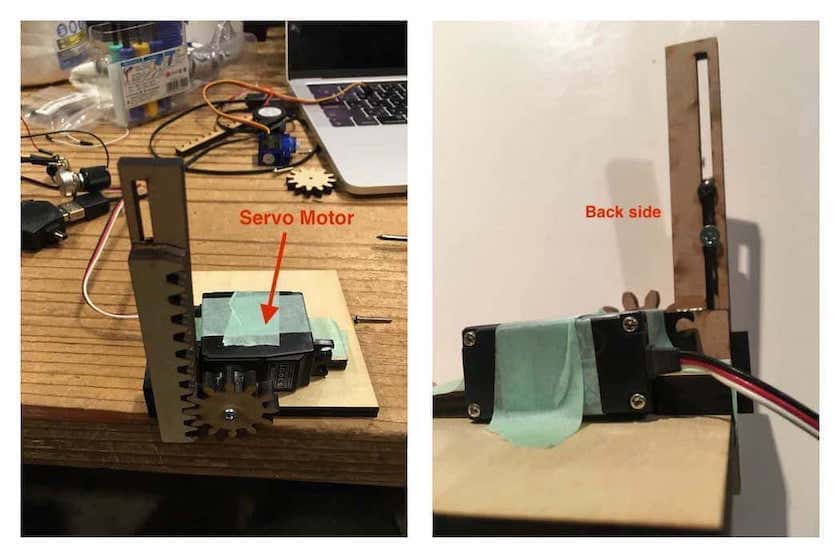
I cut the rack and pinion using laser cutter and combined with servo motor. The torque of micro servo SG90 (1.8 kgf·cm) seemed low for the project, so I chosed Futaba S3001 (4.8v 2.38kgf·cm) from the Kamakura Lab inventory.
Parts List
| parts | description | number |
|---|---|---|
| micro controller | Arduino | 1 |
| Servo motor | S3001 | 1 |
| potentiometer | 1 |
-
video
-
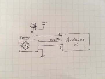
Arduino Code
#include <Servo.h>

Servo myservo;  // create servo object to control a servo

int potpin = 0;  // analog pin used to connect the potentiometer
int val;    // variable to read the value from the analog pin

void setup() {
  myservo.attach(9);  // attaches the servo on pin 9 to the servo object
  Serial.begin(9600);  //

void loop() {
  val = analogRead(potpin);            // reads the value of the potentiometer
 Serial.println(val);
  val = map(val, 0, 1023, 0, 180);     // scale it to use it with the servo (value between 0 and 180)
  myservo.write(val);                  // sets the servo position according to the scaled value
  delay(15);                           // waits for the servo to get there
}