3. Computer Aided design
Assignment of this week is to model (raster, vector, 2D, 3D, render, animate, simulate, …) a possible final project, and post it on my class page.
Planning
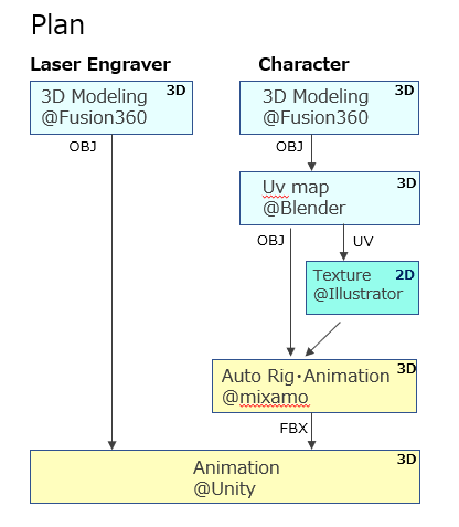
I planned following step for the assignment of this week
- Modeling mechanism of laser engraving machine
- Modeling a character which might be used in app.
- Creating UV map of the character, then editing using 2D tool such as illustrator.
- Importing models to unity and animate it
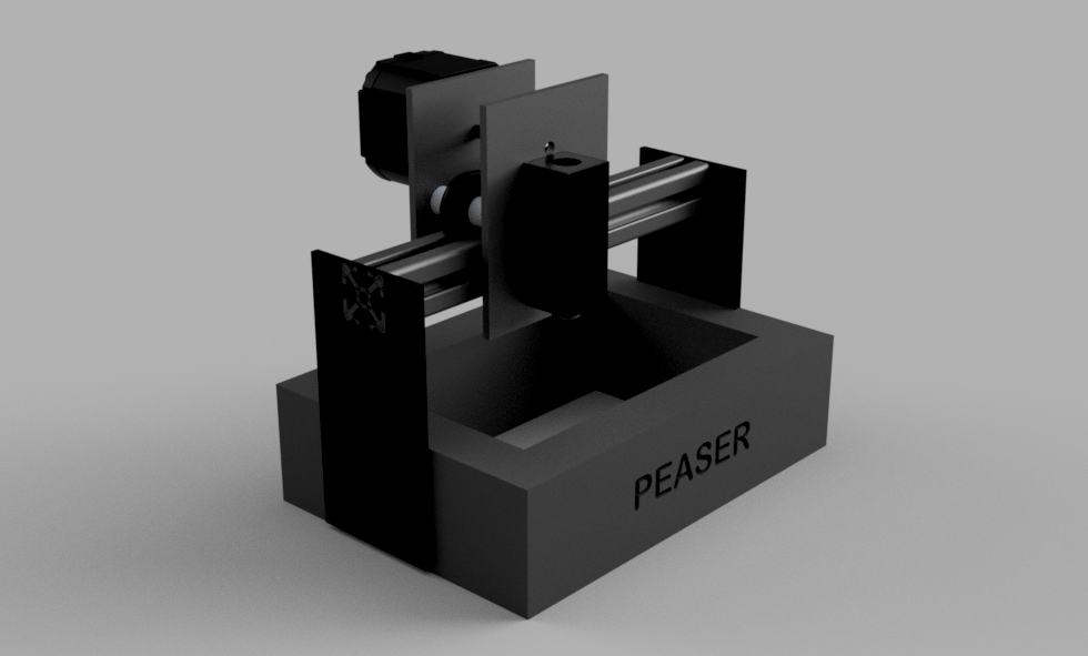
3D Laser engraver Modeling
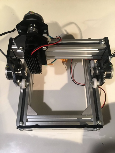
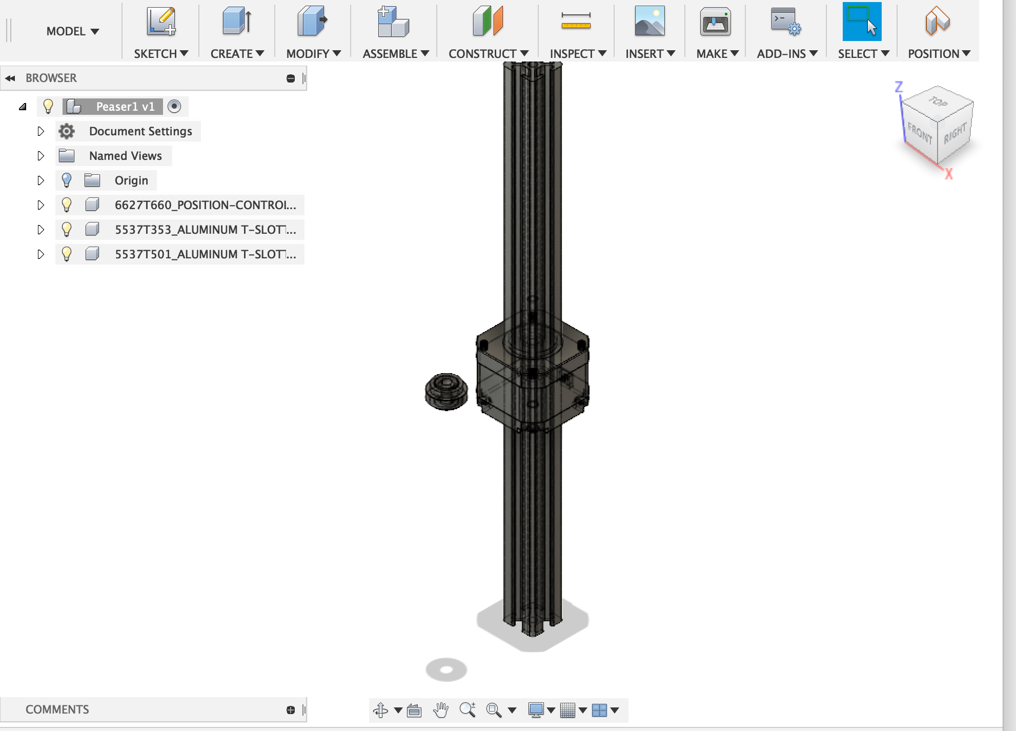
First I examined the small laser cutter I used before and decided to model upper linear rail part mainly. The goal of this week is to assemble the compartments and move it on the rail. As for software, I selected Autodesk Fusion360 because it is free (limited to students, hobbies.. ) and powerful integrated tool.
Inserting cad data
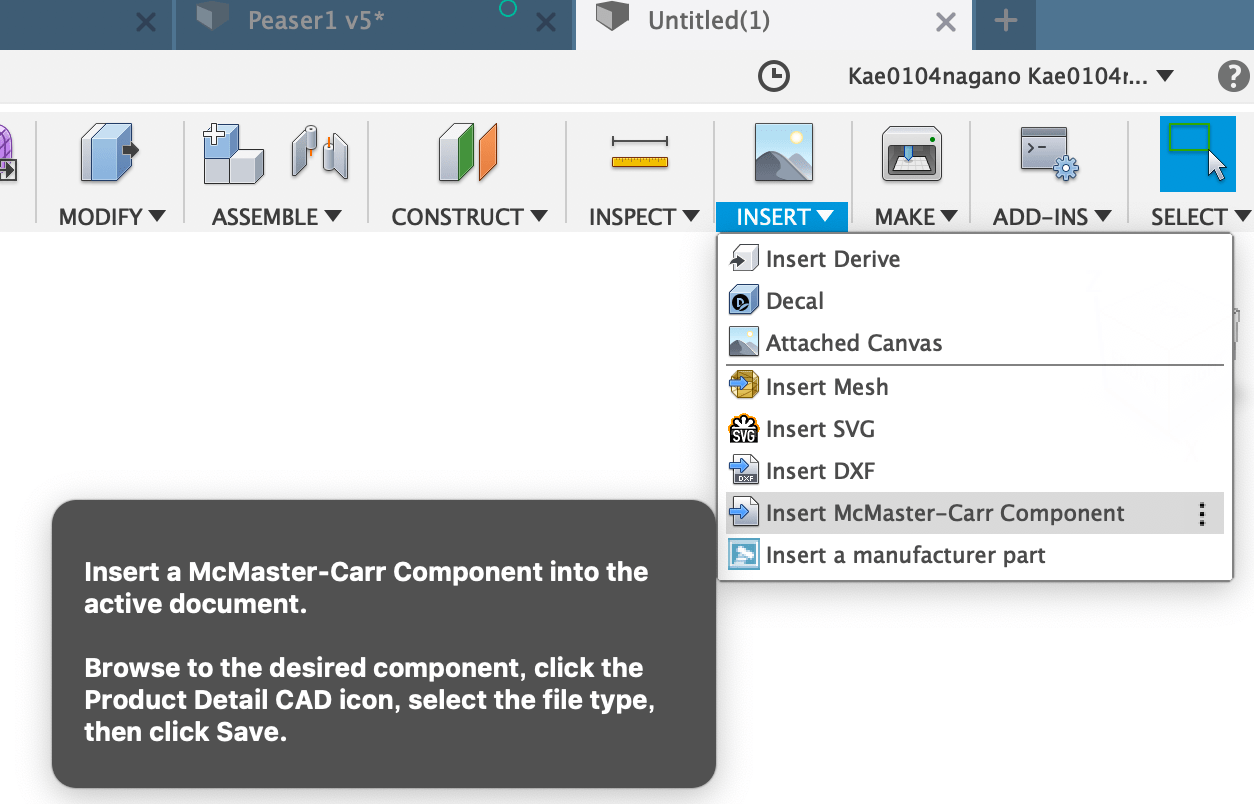
In order to model quickly, I think it is efficient to use CAD data of parts. So I learned how to download cad data from McMaster carr. I can design examination and parts purchase examination at the same time.
- Select the parts to download, then click the parts number. Order sheet is displayed.
- Click “Product Detail”, then scroll down to find download button
- Select format ( I selected STEP) and cllick “Download”
- The CAD data is imported into Fusion360
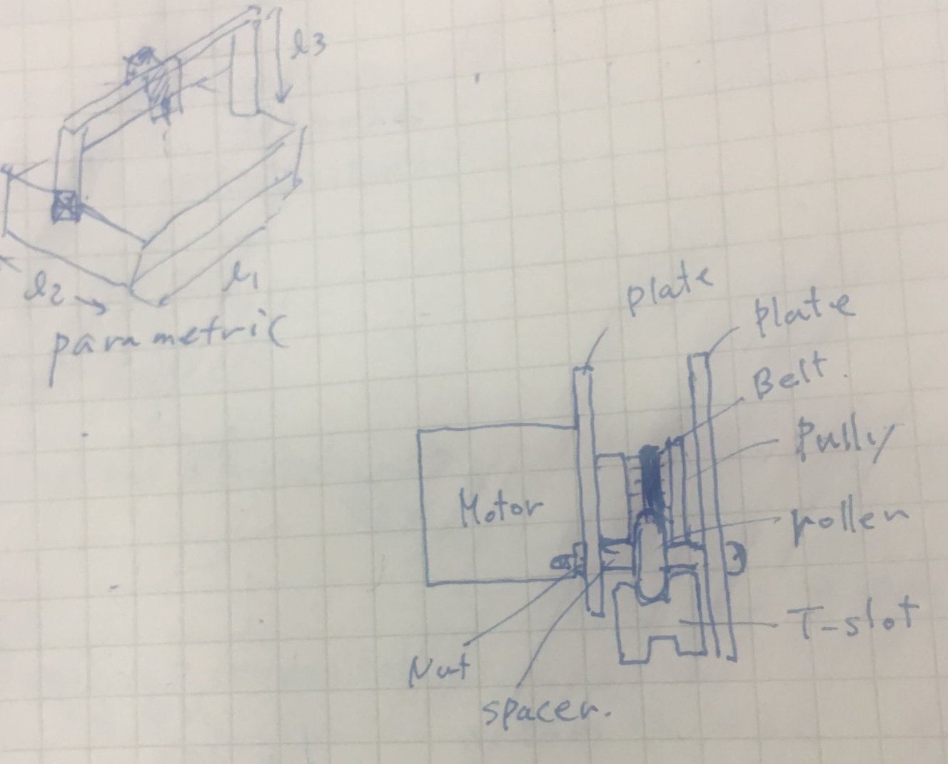
Parametric design
I defined some user parameters such as dimension of frame to enable parametric design.
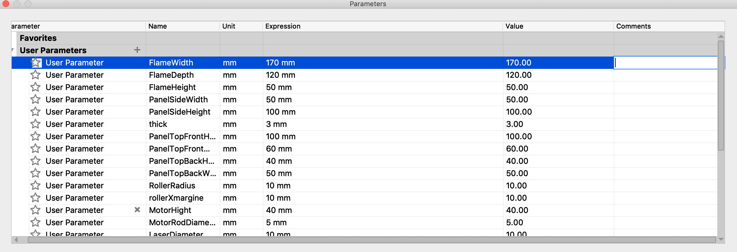
I modeled the frame using parameters and confirmed that changing the parameters will change the size of the model automatically.
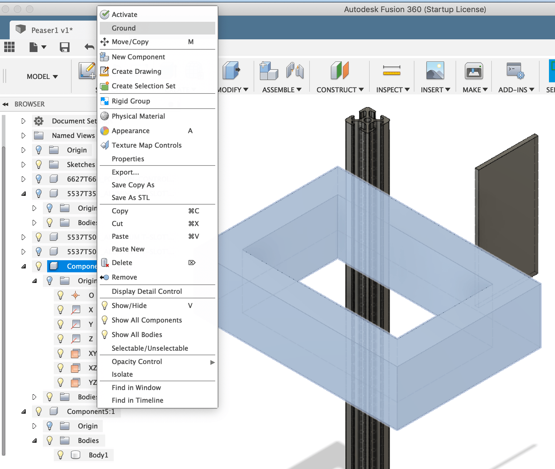
Basic assembly work
It was my first trial of assembly. I modeled side panel then converted it to the component for assembly.
Tips: Kamakura instructor advised me that when compartment is made from Body, the history of Body disappears. So it is better to make compartment first then model a body.
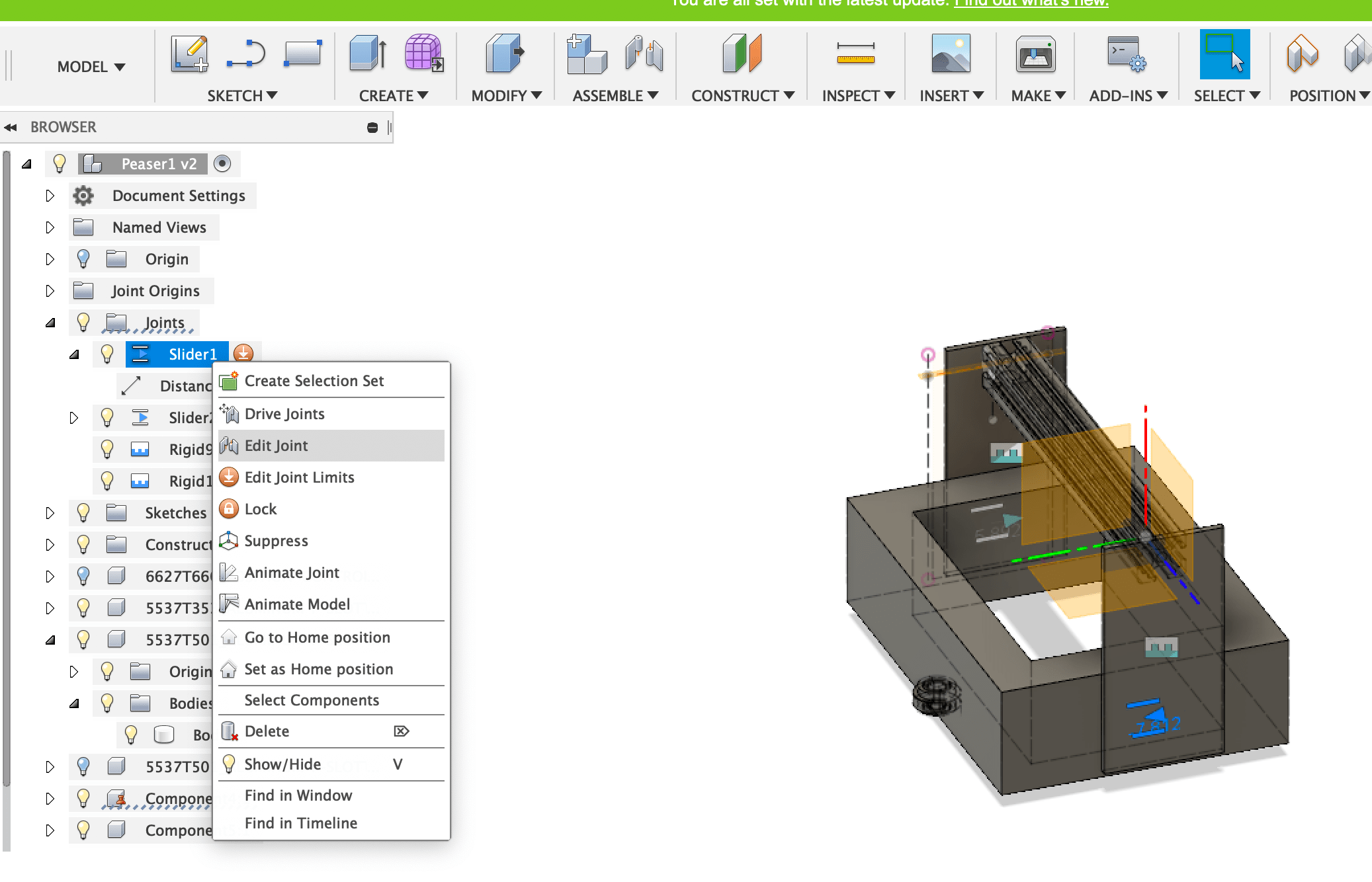
- Select “Joint” in the “ASSEMBLE’” menu.
- Select the side panel first then select the frame. It means that put the side panel to the frame. It is important which to attach.
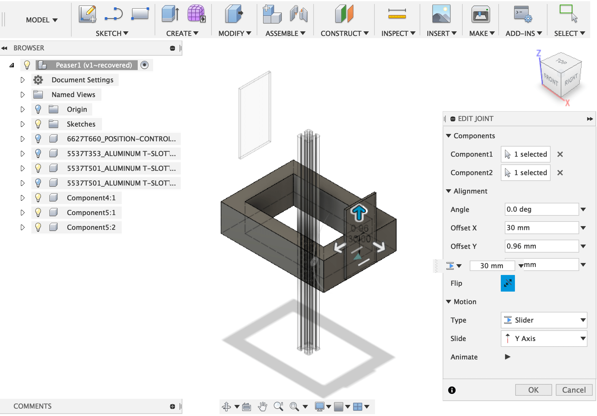
- Set frame to ‘Ground’ not to move. ( only side panel moves)
- Select joint type ‘Slider’ and adjust the position.
- Set minimum/maximum of the movement
Assemble T-slot ( a little complicated )
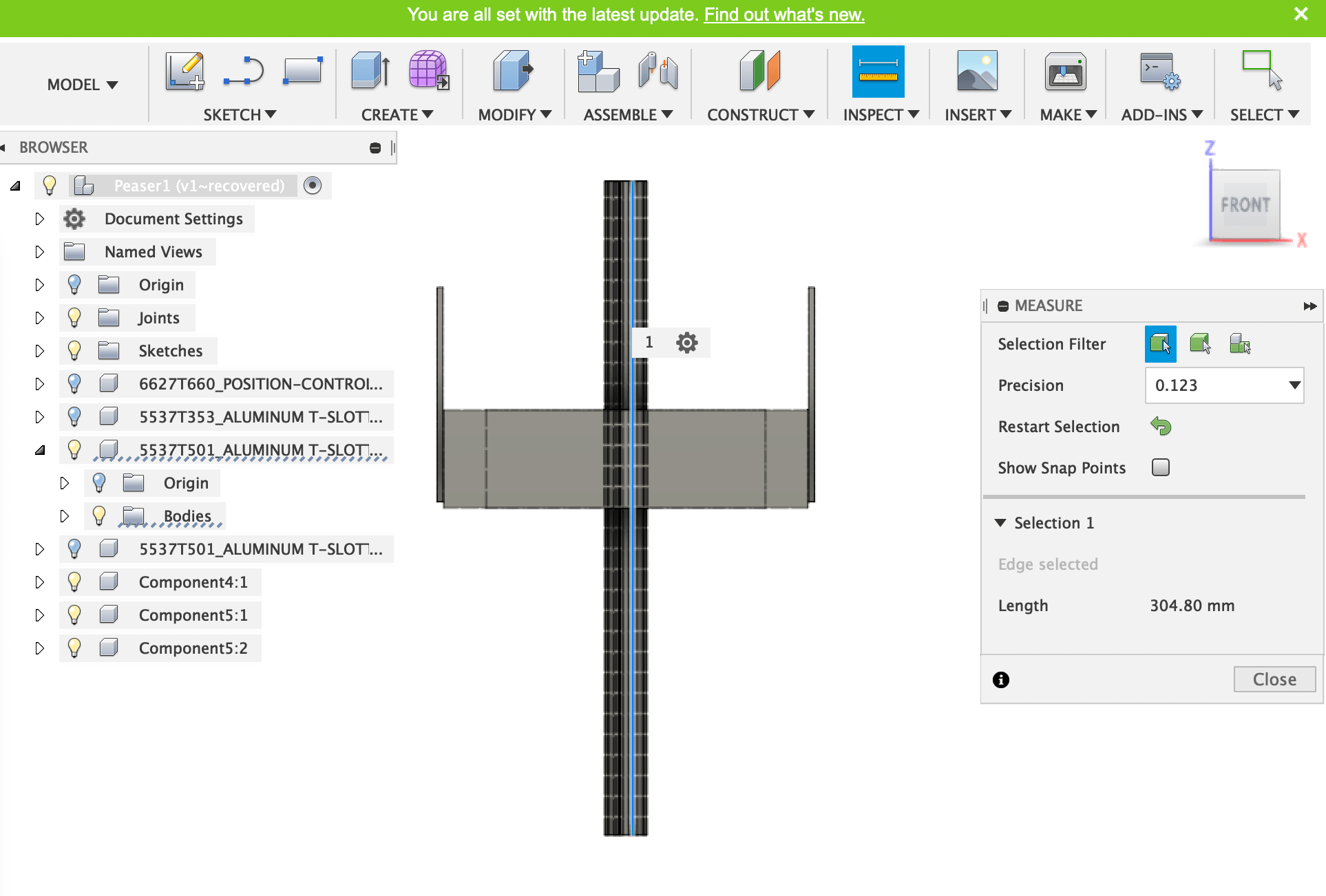
I Measured the length of T-slot first.
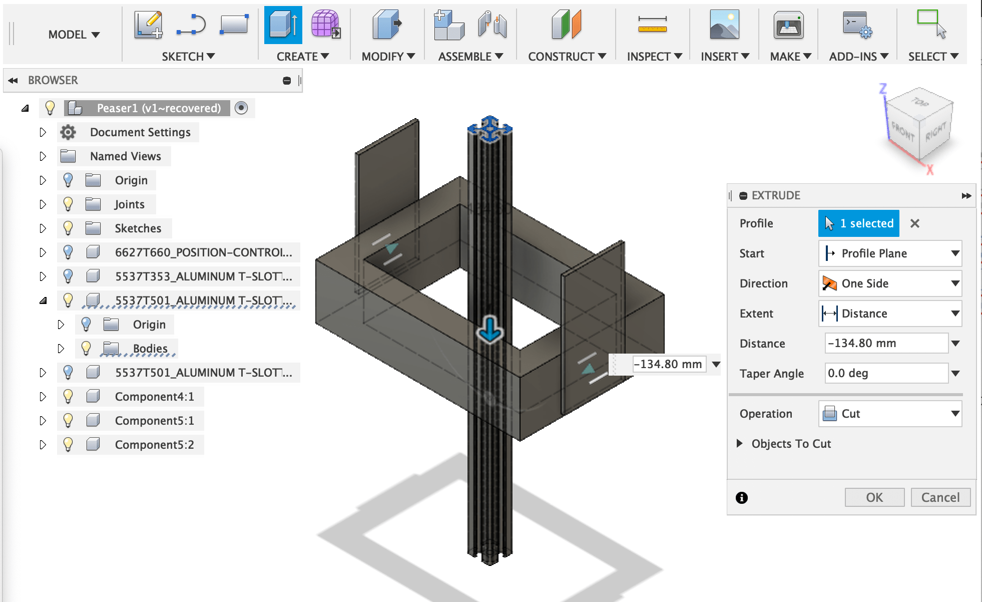
I wondered how to cut the length to fit the width of frame, then learned that “Extrude” function is one of the solution.
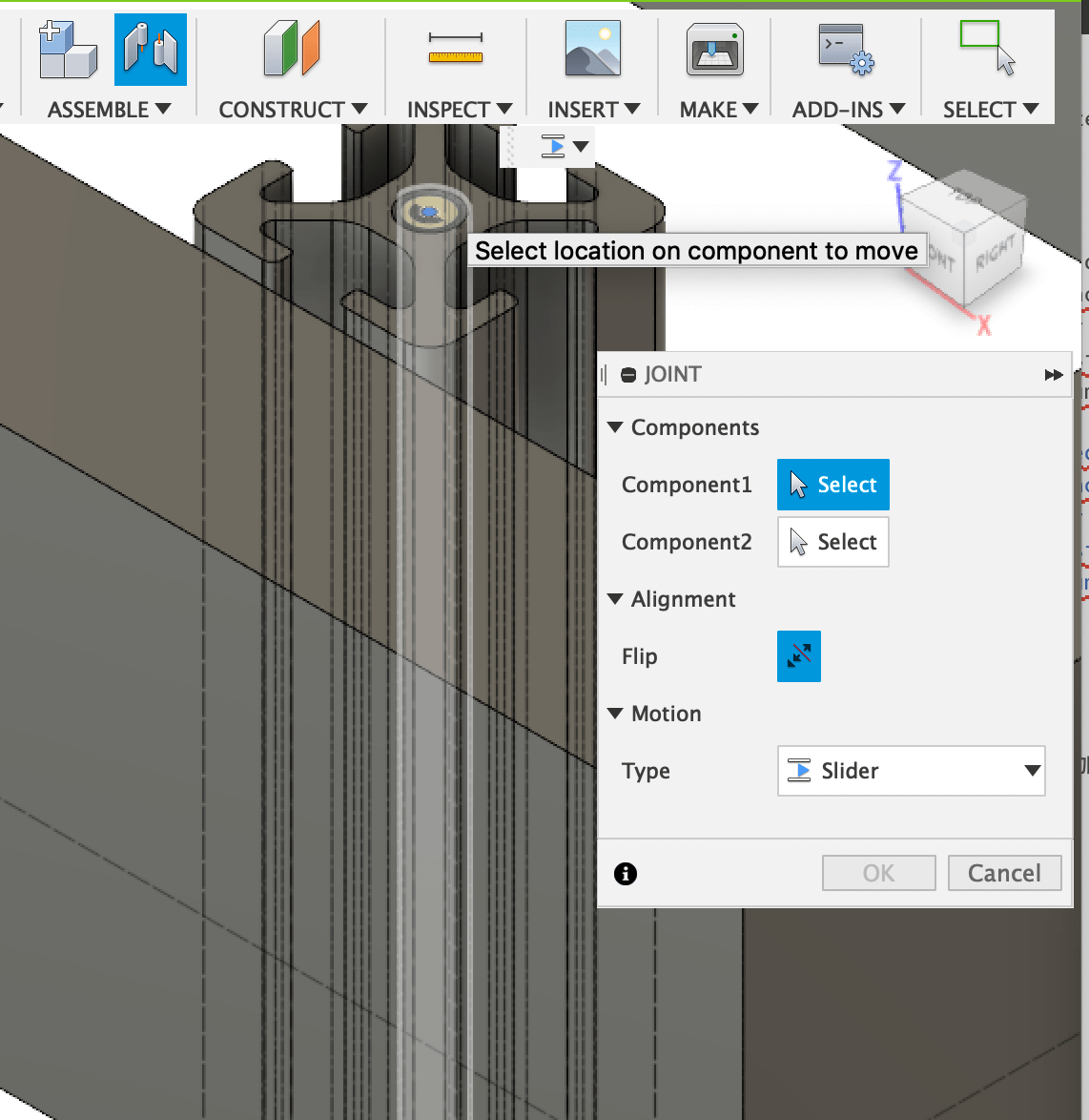
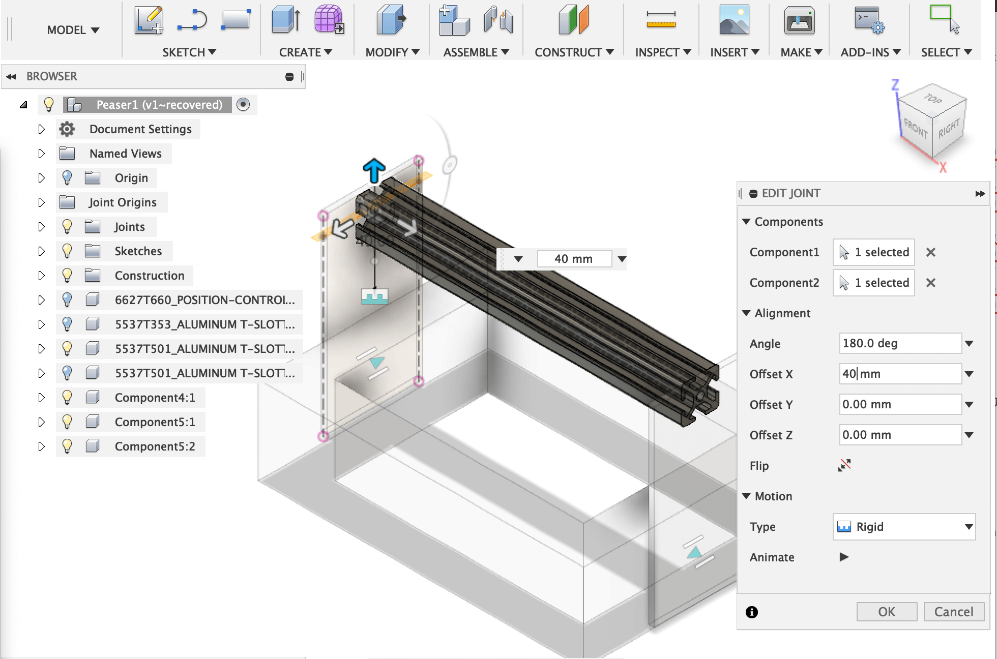
To joint T-Slot to side panel was difficult. First I selected the cross section of the T-slot but it was not attached. So I selected center (inner) cylinder of T-slot, then it attached successfully.
Assemble roller parts and rail ( more complicated for me )
I was getting used to Fusion360!
The roller components is consists of three parts, roller, bolt, and spacer. So I modeled these parts as follows.
- Sketch cross section of roller, then revolve it 360 degree
- Sketch double circle then extrude it to make spacer
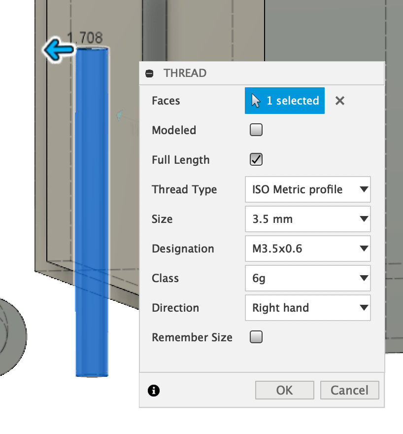
- Sketch cylinder then make bolt using threds function.
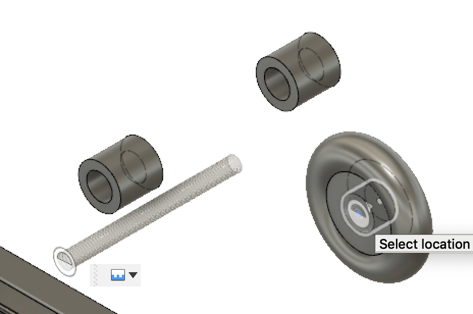
Assemble the parts together: roller < bolt < spacer
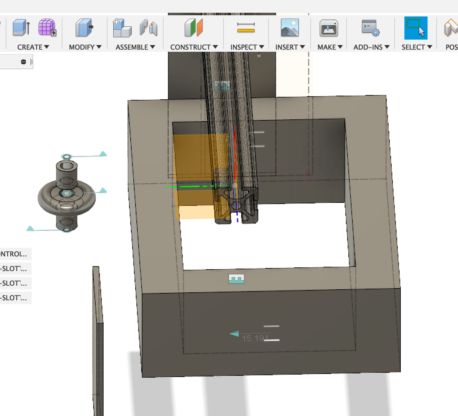
Assembling the roller component to rail was not easy for me.
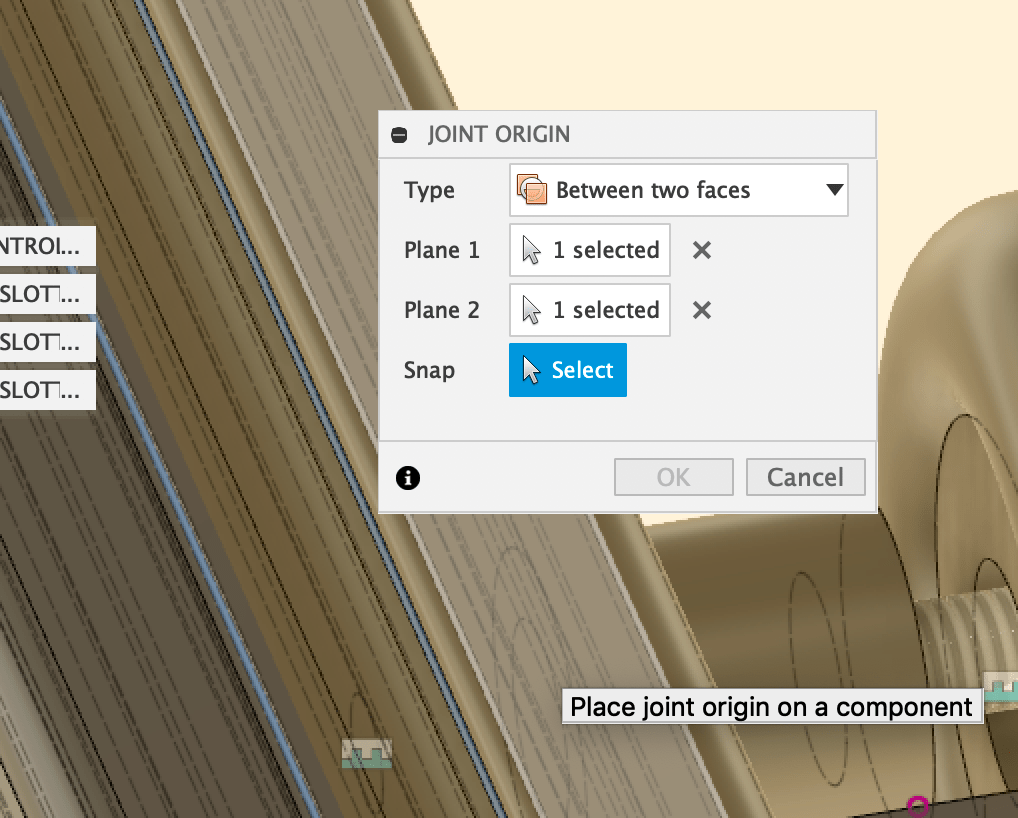
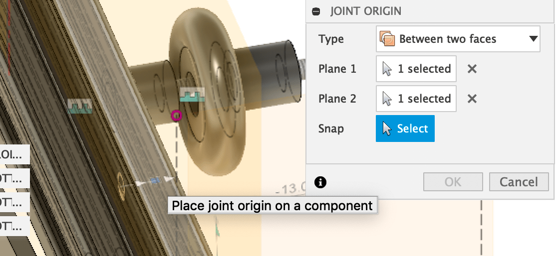
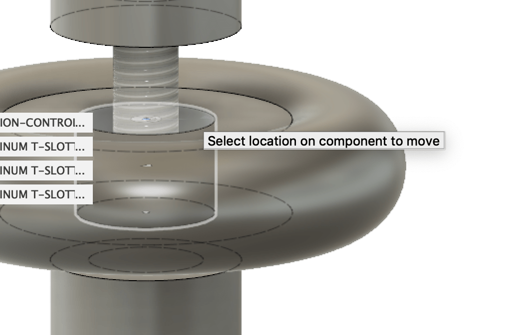
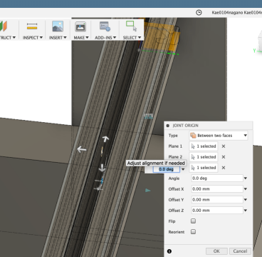
First I selected the surface of the roller, then attached it to the center of slot. However it was not able to joint. It seemed that the “joint origin” was not exist on the T slot, so I tried to created the origin at some places, then I found the following way.
- At “joint” panel, select the center cylinder of roller, then select the created joint origin. Joint type is slider.
- Tips: The roller part is consists of many parts, it is difficult to select the target point. So once the target object is highlighted, push “Command” key to lock the object, then select the target point of the object.
- Check if the roller parts move smoothly on the rail
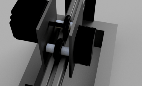
Assemble laser and motor
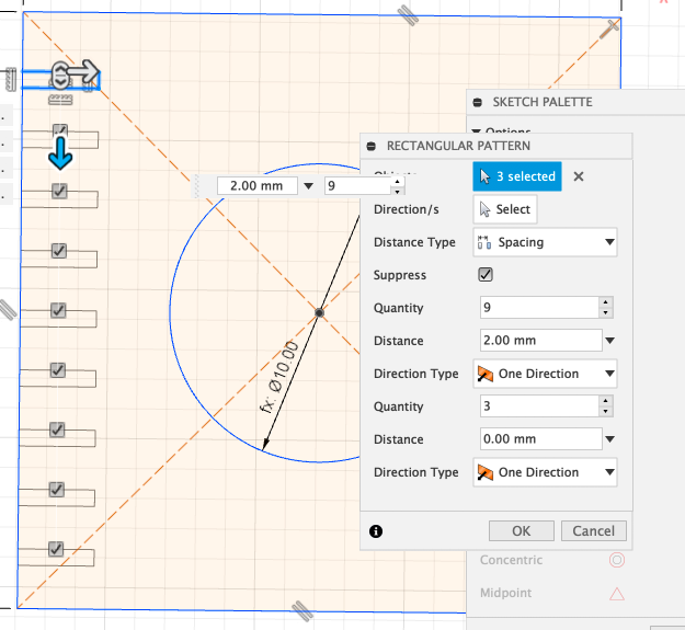
The laser unit is covered with heat sink. To model the jagged surface image, I used rectangular pattern as follows.
- Create cylinder as laser unit.
- Sketch square to make heat sink case.
To make jagged surface, sketch small rectangle first, then select ” rectangular pattern ” to copy the sketch around it. - Extrude the jagged sketch to make case.
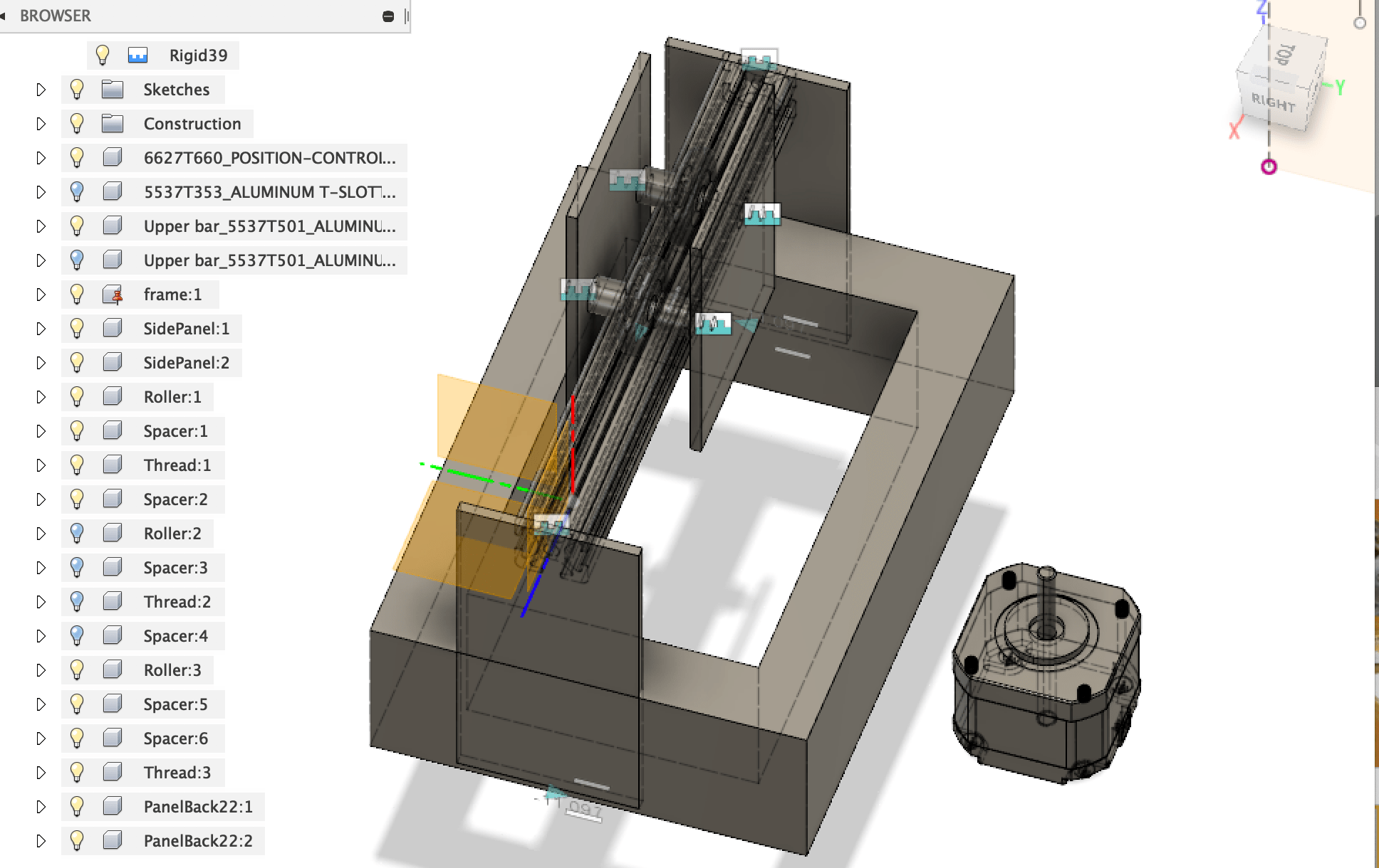
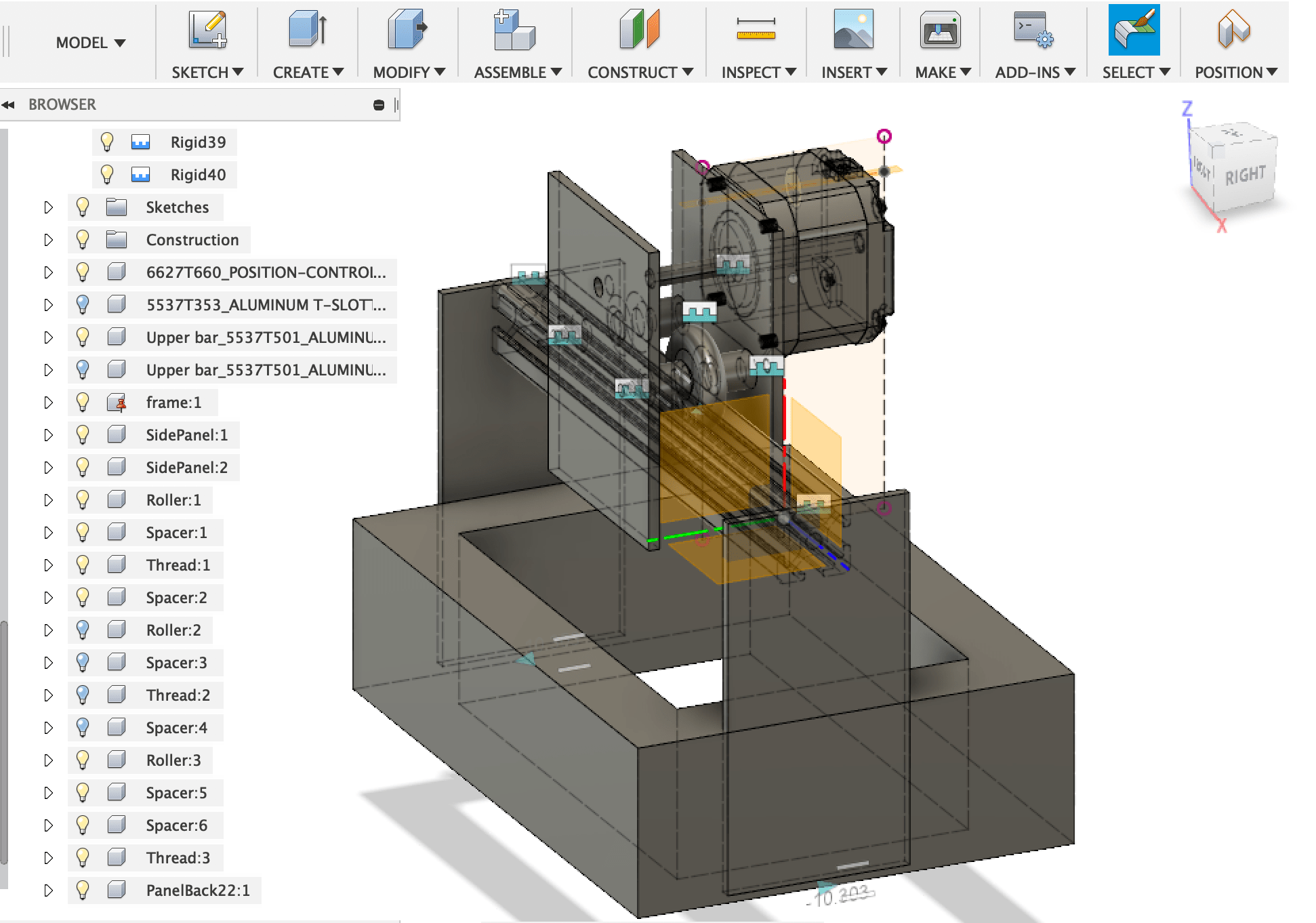
The stepping motor’s cad data was attached to the rear panel,
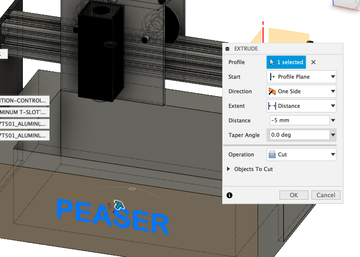
To finalize the modeling, the laser unit was attached and text “PEASER” was engraved.
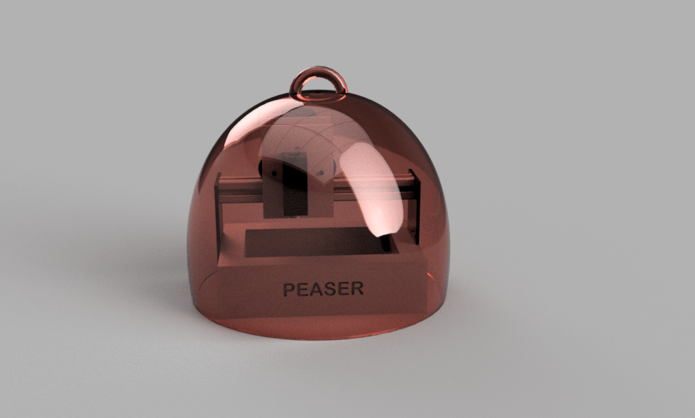
Rendering
I chose aluminium for the material of frame and tried IN-CANVAS-RENRERER. Though I do not know the standard speed, I felt it was not a long time and I was able to try various materials.
I also modeled the red dome (cloche) and combined them so that the final Project can be easily imaged.
3D Character modeling
Sculptris
First I tried sculpting using Pixologic Sculptris. I guessed that it was easier than ZBrush, but it was too dificult for me to model character. It seemed well when carving from the front, but when changing the point of view, it was terrible form. The UI was looked intuitive, but I felt to need long practice.The following is my best sculpting.
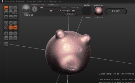
So I decided to design easy voxel type character using Fusion360. The image is monkey because my final project ‘PEASER’ engraves bananas and nuts, so it reminds me of ‘Curious George’ I love.
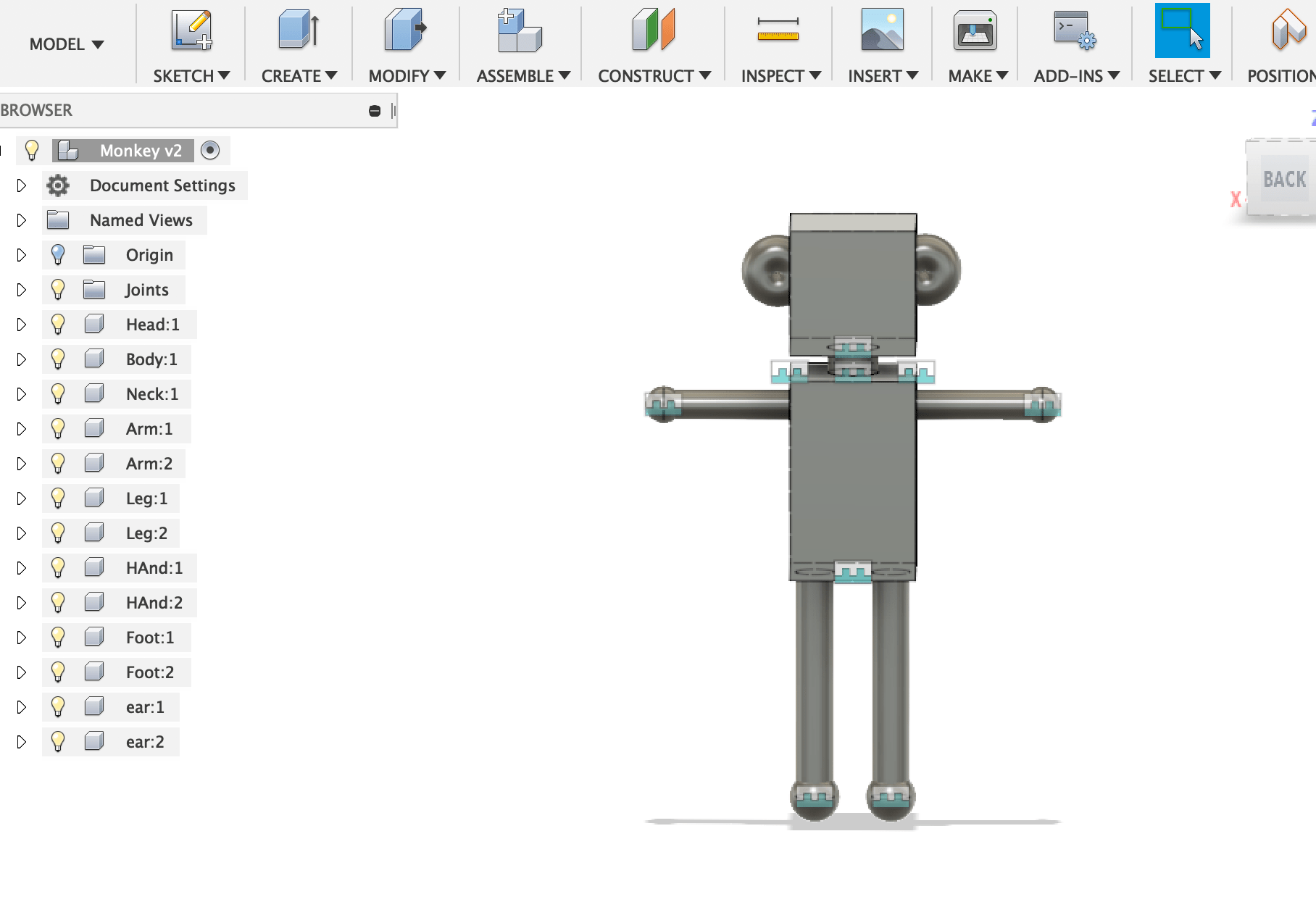
I realized that I can’t export OBJ format directory from the Fusion360 work space. So I selected the model in the data window, then uploaded it to Fusion cloud and made OBJ file.
Auto rig and animation @ Mixamo
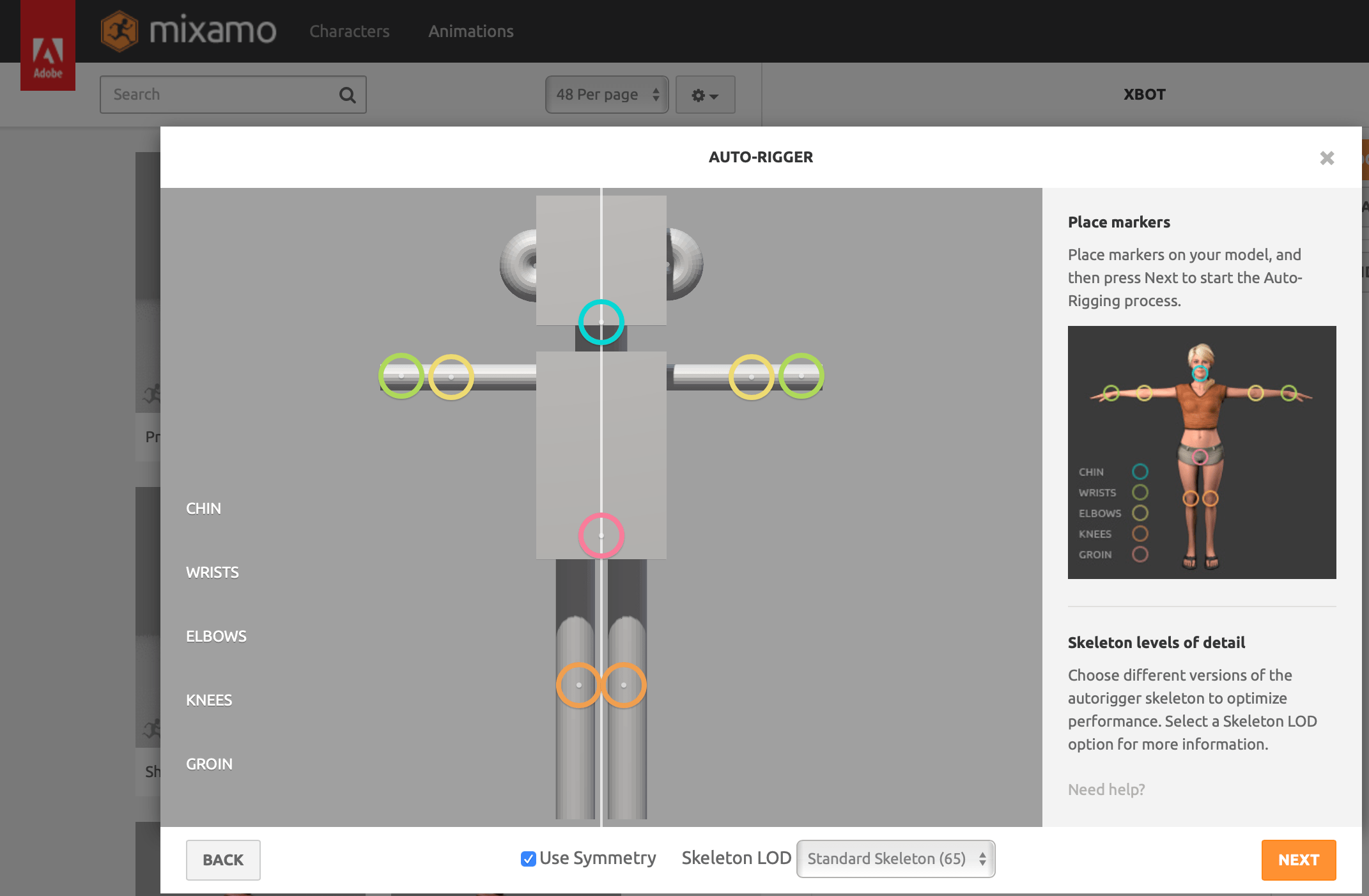
I am interested in Mixamo, but I have not used it yet. So I tried it this time, it was very easy and fun! First I uploaded the monkey model as character. of course it is able to choose one from example of characters. The UI to place markers of rig on the character was easy and intuitive. I supposed that some kind of conversion would be necessary for Unity, but “FBX for Unity” was already selectable at export window.
2D drawing
UV map
As I planned to use 2D software to draw texture of the character, I created the UV map first using Blender. It was a slightly complicated sequence, so I wrote it down below so as not to forget it.
- Import OBJ monkey model to Blender
- Run UV image editor and create new texture image
- Select the object in editing mode, then select “ Smart UV Project”
- Select material tab and select New
- Set favorite color
- Select render tab and push Bake to make texture
- Select “Save As Image” to export the texture
- Export the model as OBJ mode
Vector tool
Illustrator
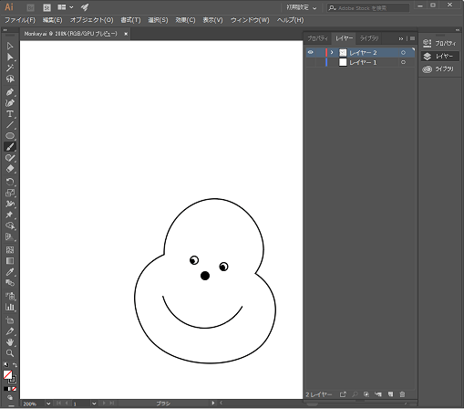
I practiced writing a monkey face with curved tool since bezier tool looked difficult for me.The place clicked became an anchor point and it was easy to toggle the two mode, smooth point and corner point.
Raster tool
Photoshop
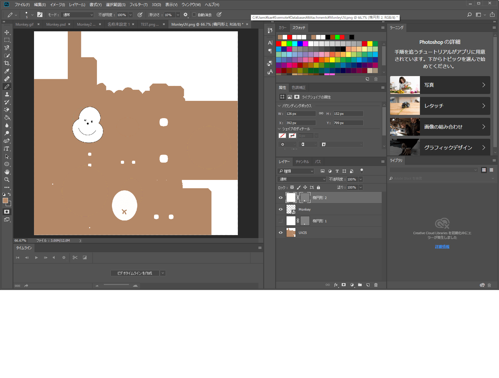
I colored the UV map and placed the monkey face. I also tried pen tool of Photoshop, but I felt that Illustrator’s UI was better for me.
I tried to import the textured model to Mixamo, but it did not work. I will continue to examine.
Game engine
Unity
I imported Mixamo FBX model to Unity project. After placing the prefab model to hierarchy window, I created new Animation Controller, then attach it to the model. The animations by Mixamo were dropped to the AnimationController and set loop sequence as follows. It was so easy that I would like to try interactive game / application using various Mixamo animations.
Textured OBJ model was not able to import to Mixamo, I imported to the OBJ model and UV map (ping file) directly to Unity. I created new material and dropped the texture to albedo.
So the left monkey with face is OBJ model, and right dancing model is Mixamo FBX.
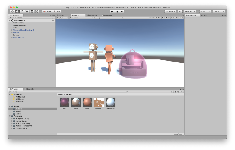
To make video, I tried to import the official recording asset recorder asset of Unity. It is very simple interface and useful.
Files
- Laser Engraver 3D Model@ Fusion360
- Laser Engraver 3D Model@ Fusion360 f3d format
- Character 3D Model@ Fusion360
-
Monkey vector design : Illustrator format