"" -
Output Devices
For this assignment first I decided to do the video board, as I find it would be useful for some experimenting with my final project. As I didn't have any RCA monitor around, I decided to do first a RGB board, and if I had time I tried the video board.
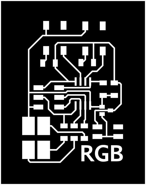
RGB Board
Setting up
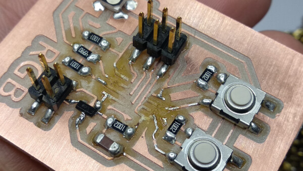
To Neil's RGB board I wanted to add some input devices, so I added two switch buttons to control the colors of the RGB led. To do this I based my work on Neil's PCB design.
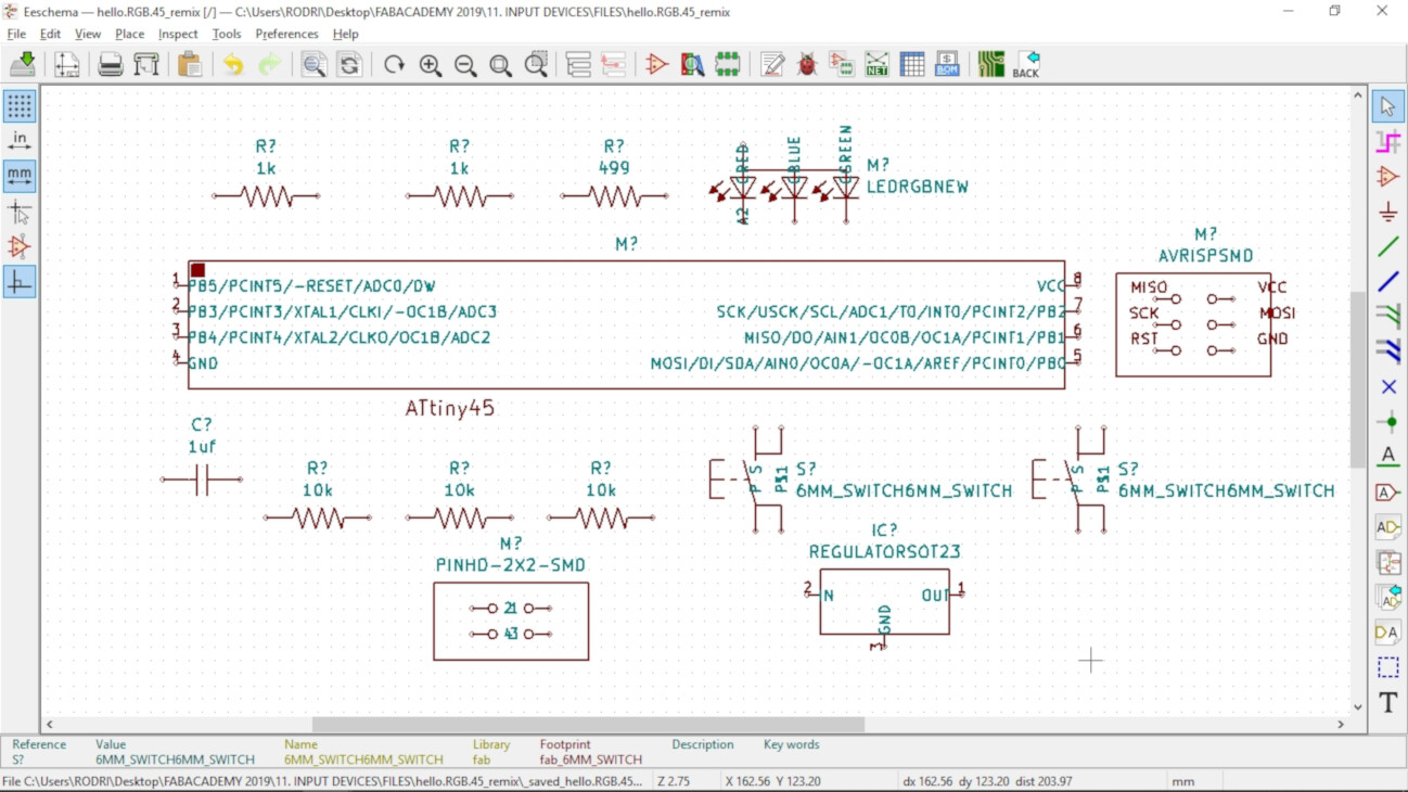
First I opened KiCAD, opened the schematic window and placed all the components on the workspace.
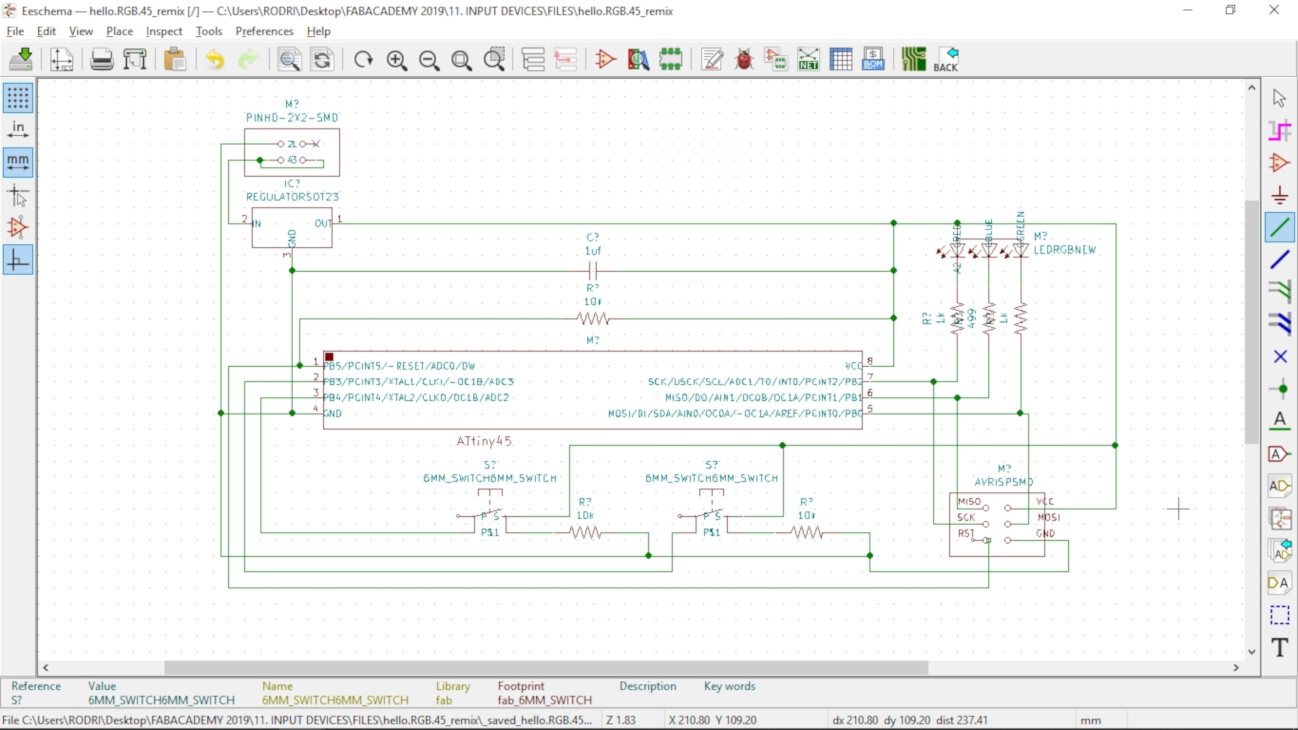
Then I connected all the components together.
Then I opened the PCB design window, and imported the netlist of the components.
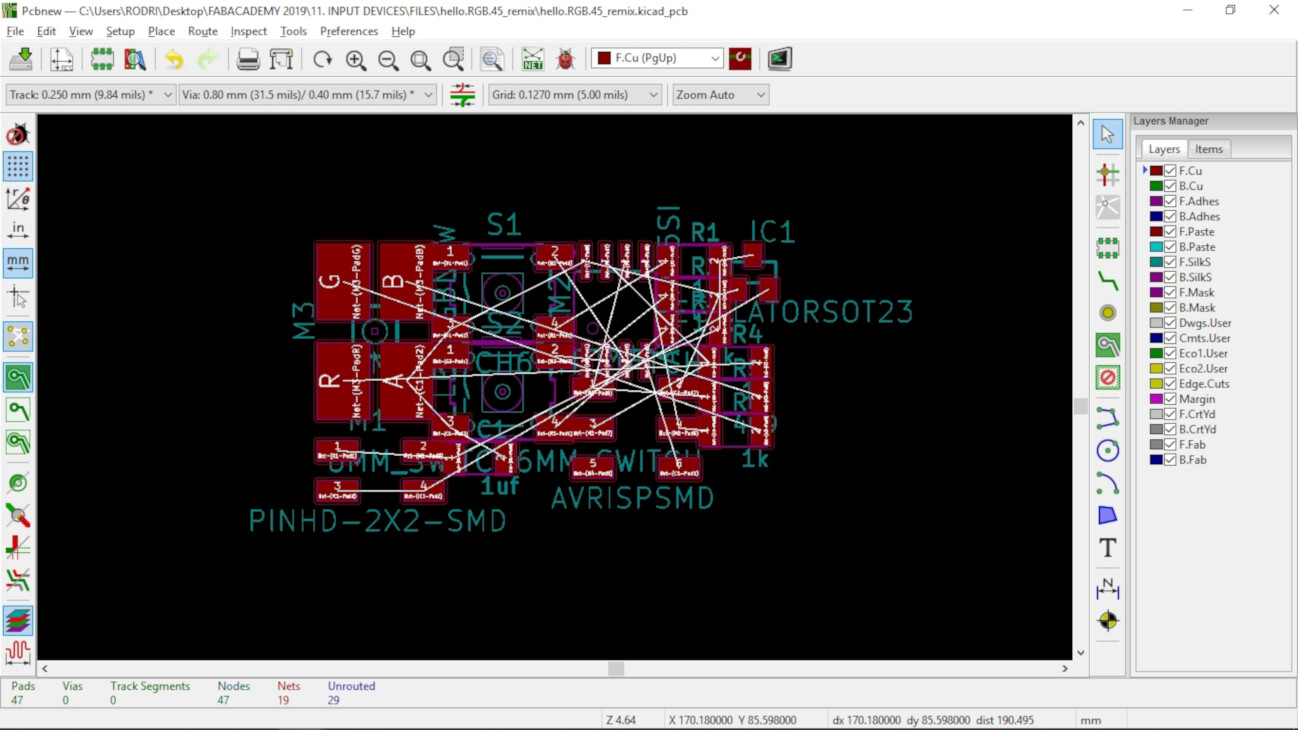
Finally I connected the components using these design tools:
- Clearance: 0.127 mm = 5 mils
- Track Width: 0.381 mm = 15 mils
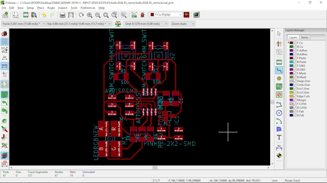
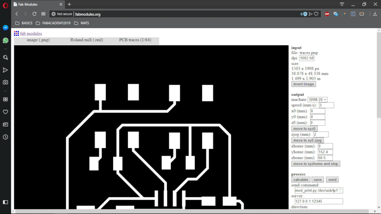
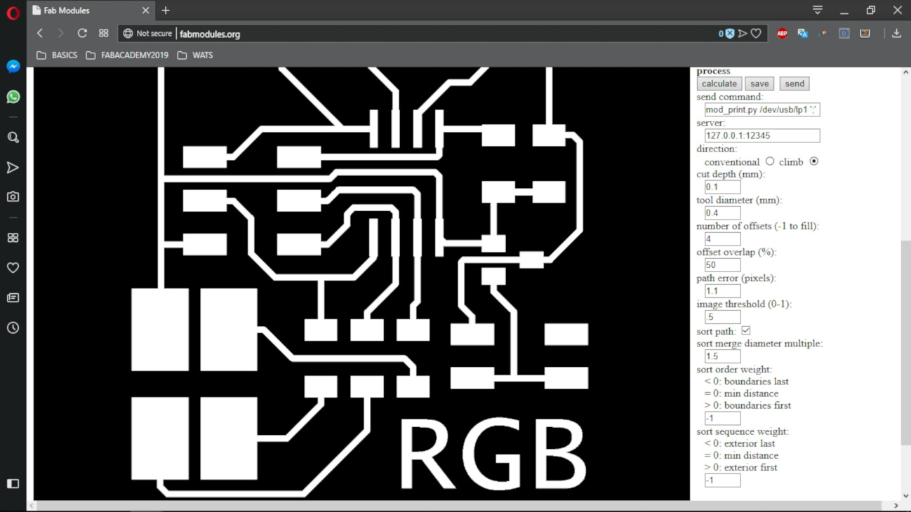
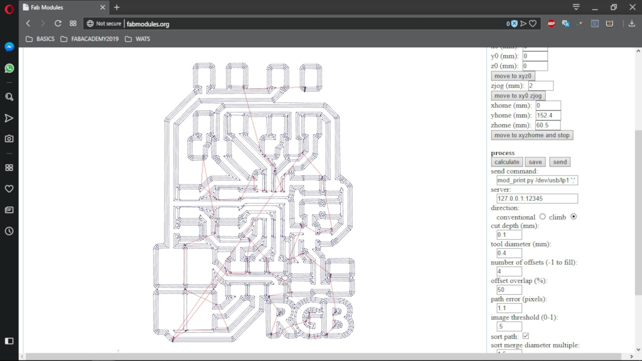
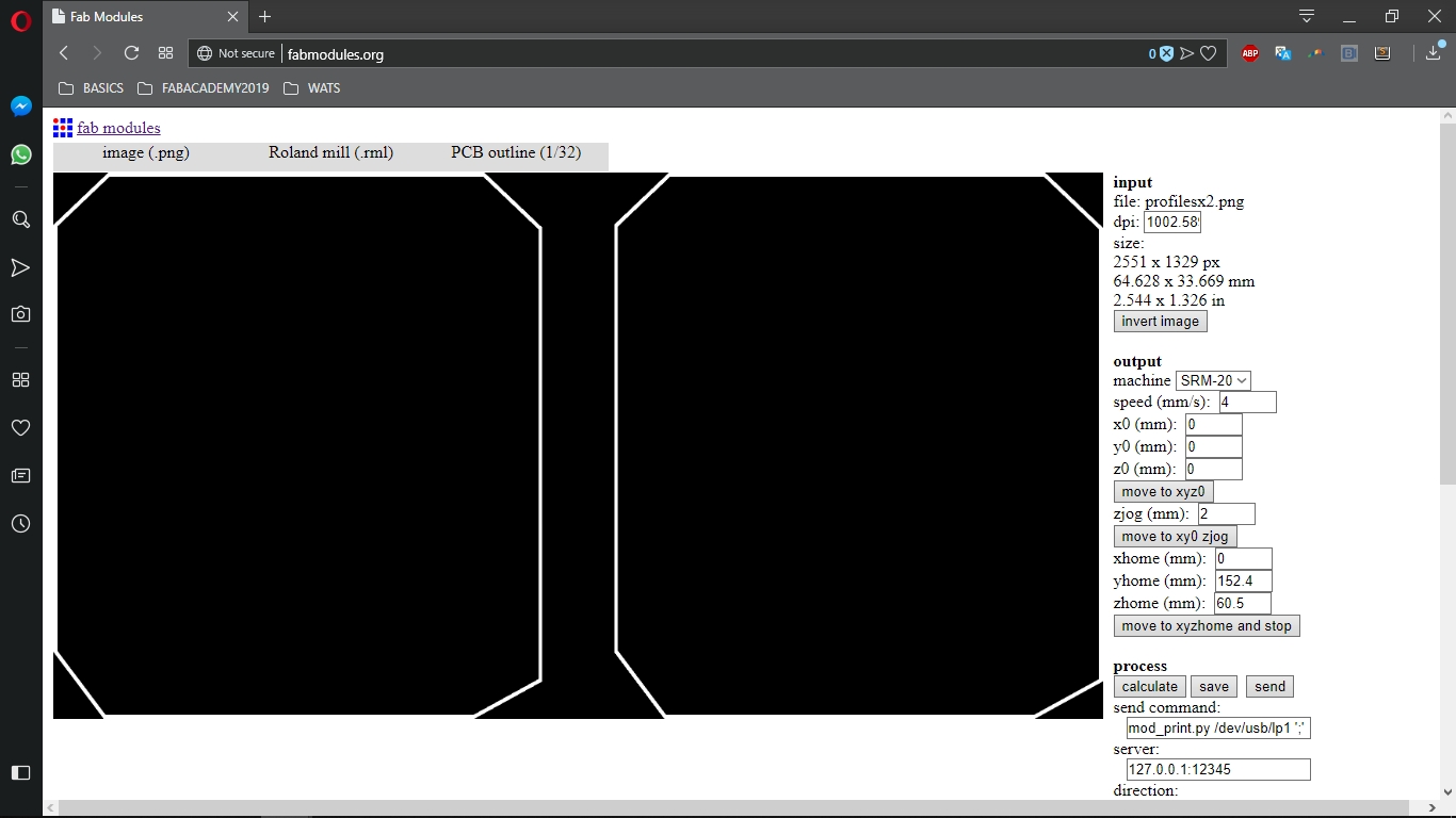
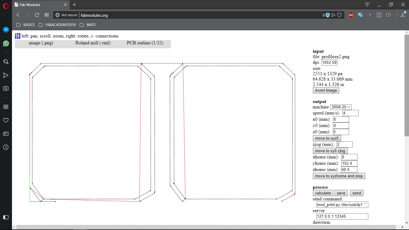
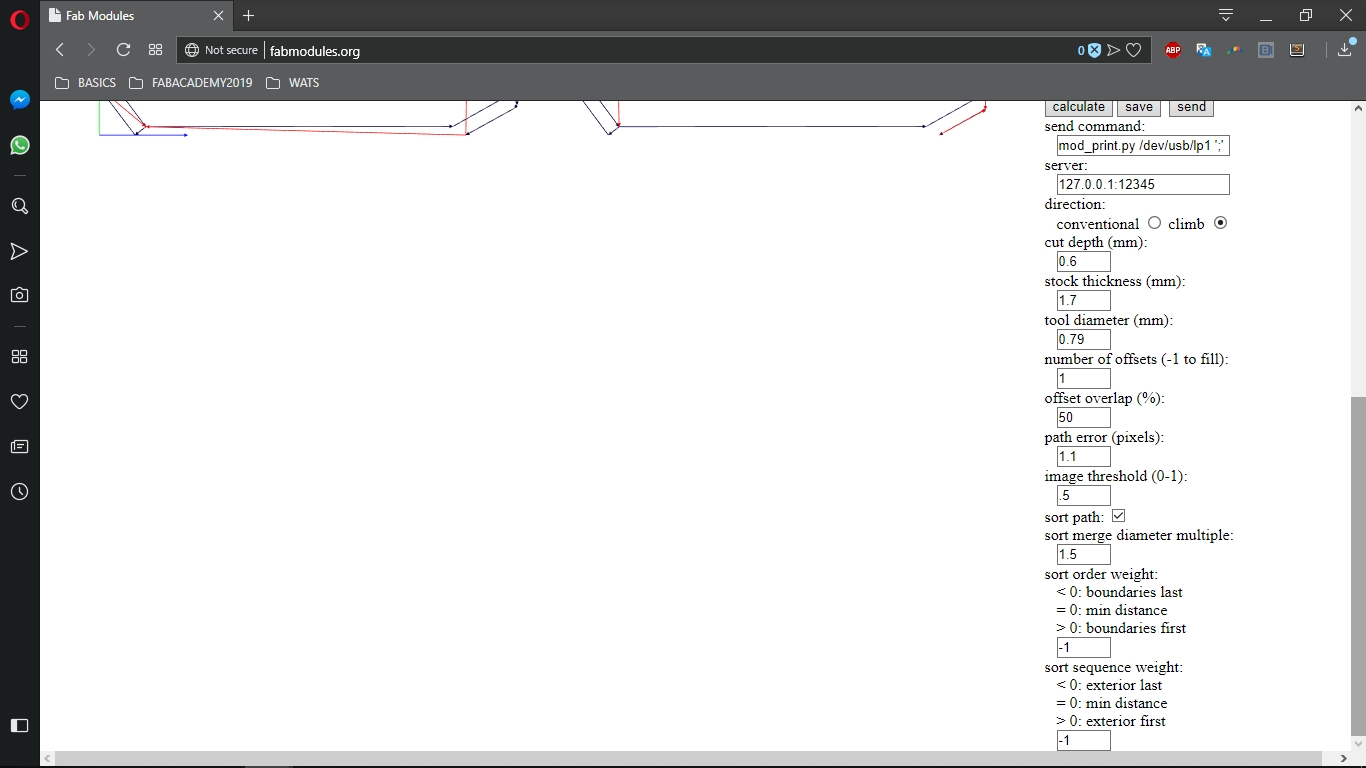
I then used FabModules to generate the .rml files to mill the board
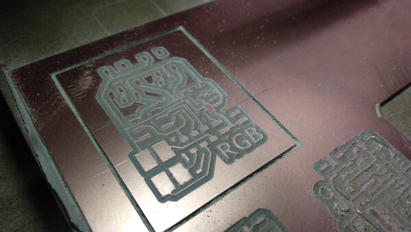
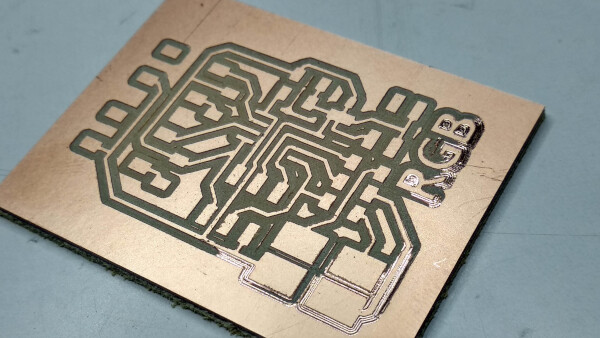
Fabricating the board
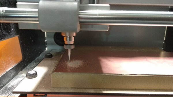
I used the Roland SRM-20 to mill the board. I used a 1/64 bit mill to cut the traces and a 1//32 bit mill to cut the outline of the board.
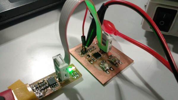
After milling the board I soldered all the components, and connected the ISP pins to the FabISP board to program it.
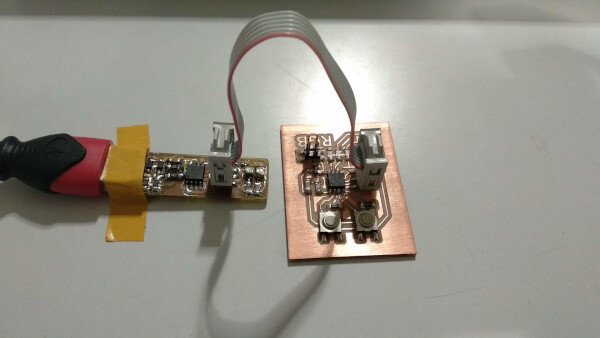
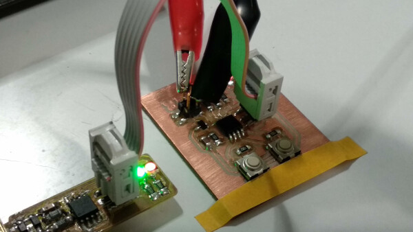
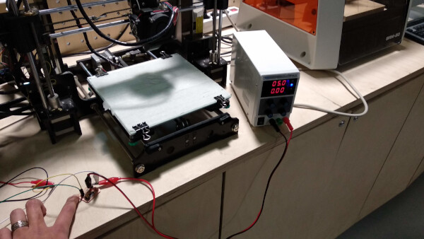
At first I was a little confused because I noticed that the RGB board don't have FTDI pins. I then learned that in all other boards I have made, the FTDI functions to power the board. Then this board is power by the 2x2 pins. So I used an external power supply to power the board to 5v.
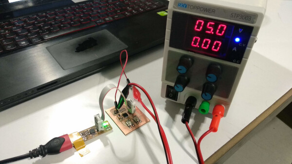
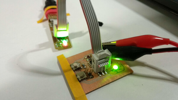
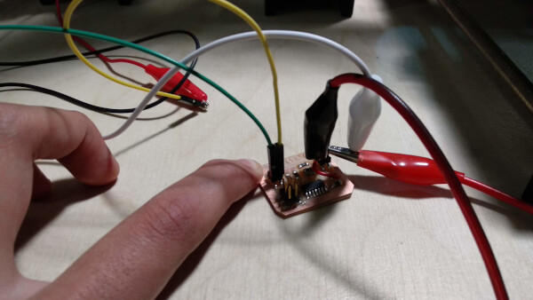
I carefully connected the alligator clips to GND and VCC on the 2x2 pins.
Before I tried to burn the bootloader, I noticed that I made a mistake in the board. Some of the traces that shouldn't be connected together, were. Unfortunely this traces were the ones just beneath the ATtiny 45. So I desoldered the ATtiny trying to be careful but I broke a few traces in the process.
After giving it a few tries at soldering back the ATTiny, I decided that the board was bad enough.
So I decided to mill another one.
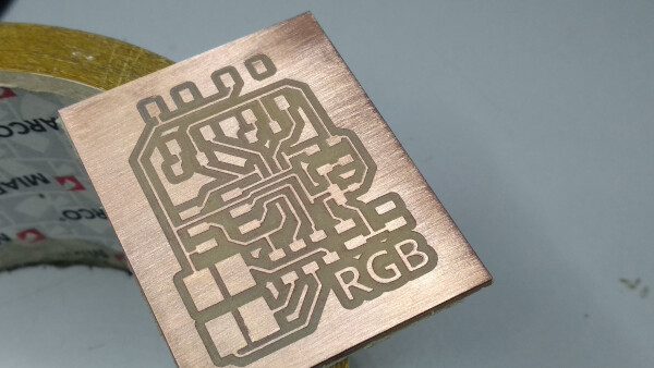
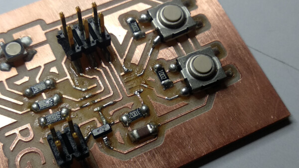
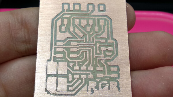
There were still a few mistakes on some connections. I noticed that some traces were too thin and closed to each other, so FabModules just didn't generated the milling path as it was supposed to. Instead of changing the file on KiCAD, I decided to separate this traces manually using a cutter. This was the result:
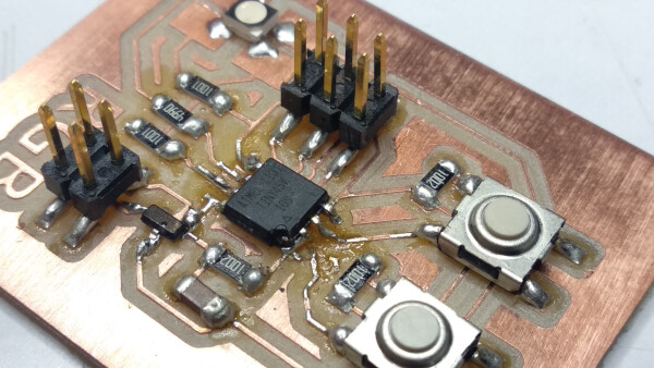
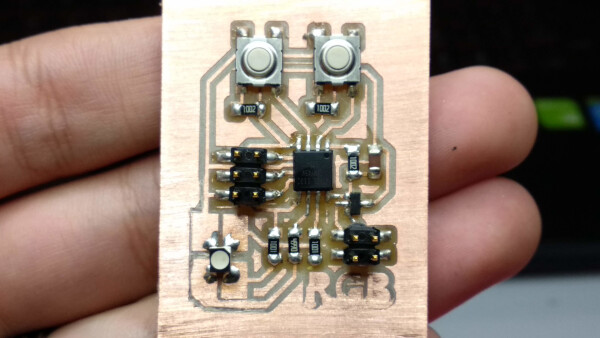
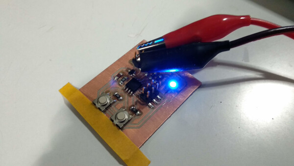
I then checked everything was okay using the multimeter, and after that I soldered the components. This time the result was better than the previous one.
After this, I connected carefully again the alligator clips of the external power supply to the GND and VCC pins of the board. I also connected the ISP pins of the board to the FabISP.
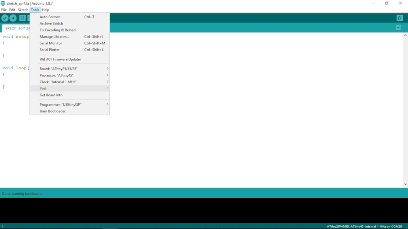
As I programmed the RGB board through the FabISP, the port section in the Arduino IDE seems like is not being recognized, but that is normal, as it is not connected to a usb seperately through FTDI as the other board I made. So in the tools section, I setted up this:
- Board:"ATtiny25/45/85"
- Processor:"ATtiny45"
- Clock:"Internal 1 MHz"
- Programmer:"USBtinyISP"
I then clicked "Burn Bootleader"
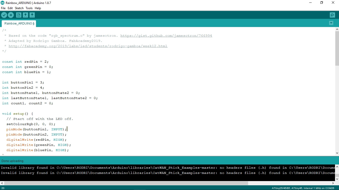
After recieving the message "Done burning bootloader", meaning everything was okay, I then wrote this code:
You can download this code at the Files section, at the bottom of this page.
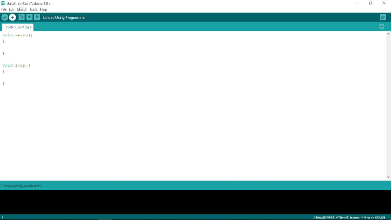
To upload the code to the RGB board, I held Shift+Upload button. Instead of the usual "Upload" message, it should say "Upload Using Programmer".
After uploading the code, the RGB led began changing colors.
After doing some programming I wanted to implement something more interesting. So I found this code that cycle an RGB led through the colour spectrum. So I found that It would be interesting to add some trigger with the buttons. At the beggining I was having a lot of troubles making the buttons work, without touching them I was recieving some voltage, and that wasn't suposed to happen, it was supposed to be at 0v while not pressed. As I didn't put a FTDI connector to the board, I couldn't read the serial data from the board.
While testing with the multimeter I noticed that I had make a wrong connection on both buttons. I soldered the resistors to the wrong pin of the button. So while I wasn't pressing the button, there was no connection to the pin of the microcontroller, so it was recieveing a parasitic voltage. What I did to solve this was to make a cut between the wrong pin of the button and the resistor to divide them, and solder wires from the resistor to the right pin of the button.
I adapted the code to use both buttons to trigger a sequence of the color spectrum pattern of the original code.
You can download the full code at the end of this page, in the files section. At the end, I solved this problem with the buttons, although it took me a whole day to find the actual problem.
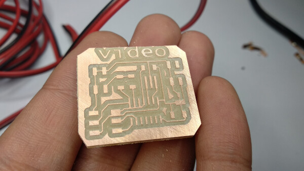
Video Board
Setting up
First I replicated Neil's design for the board as I didn't totally understand how does it work, and would be easier for me to test it and experiment with it before doing changes.
I used KiCAD and first placed all the components on the workspace.
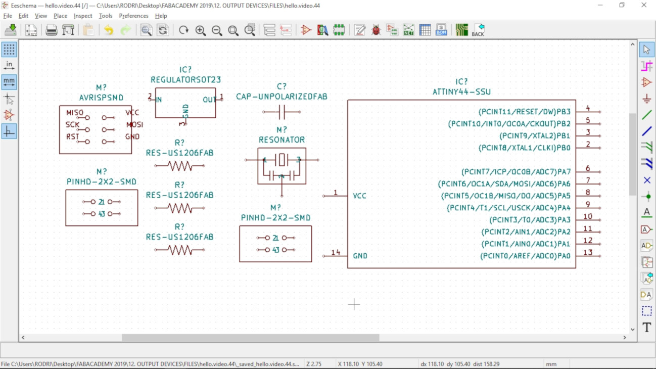
Then I connected all the components following Neil's board as a guide.
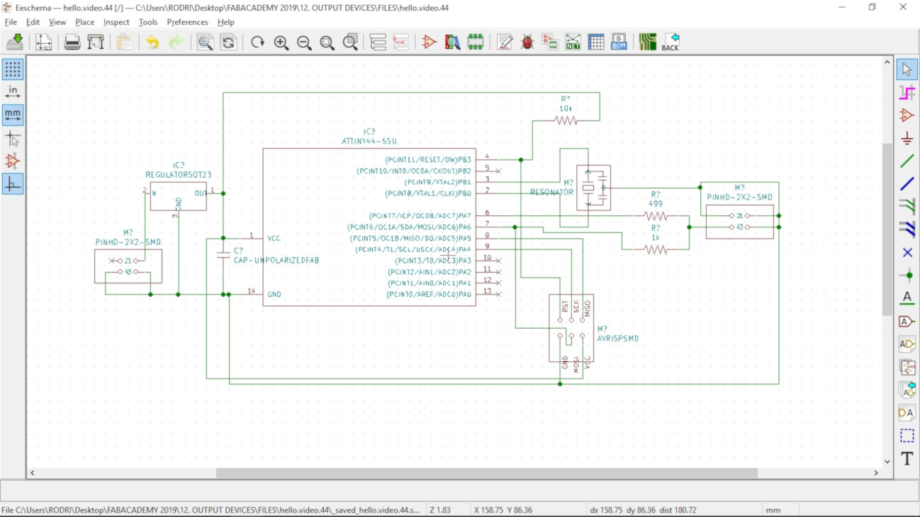
Then I moved to the PCB design window and reordened the components.
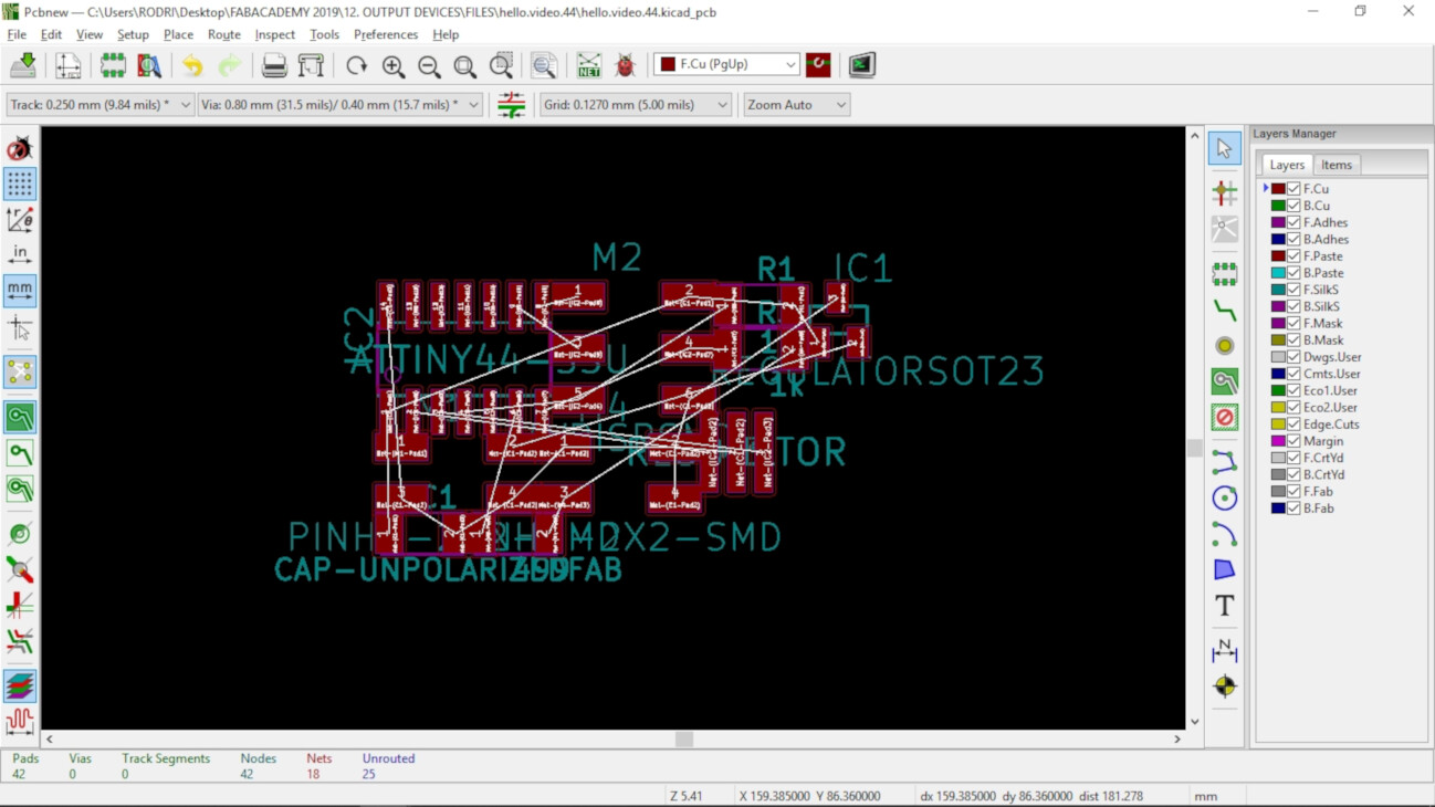
Finally I wired the components using these design tools:
- Clearance: 0.127 mm = 5 mils
- Track Width: 0.381 mm = 15 mils
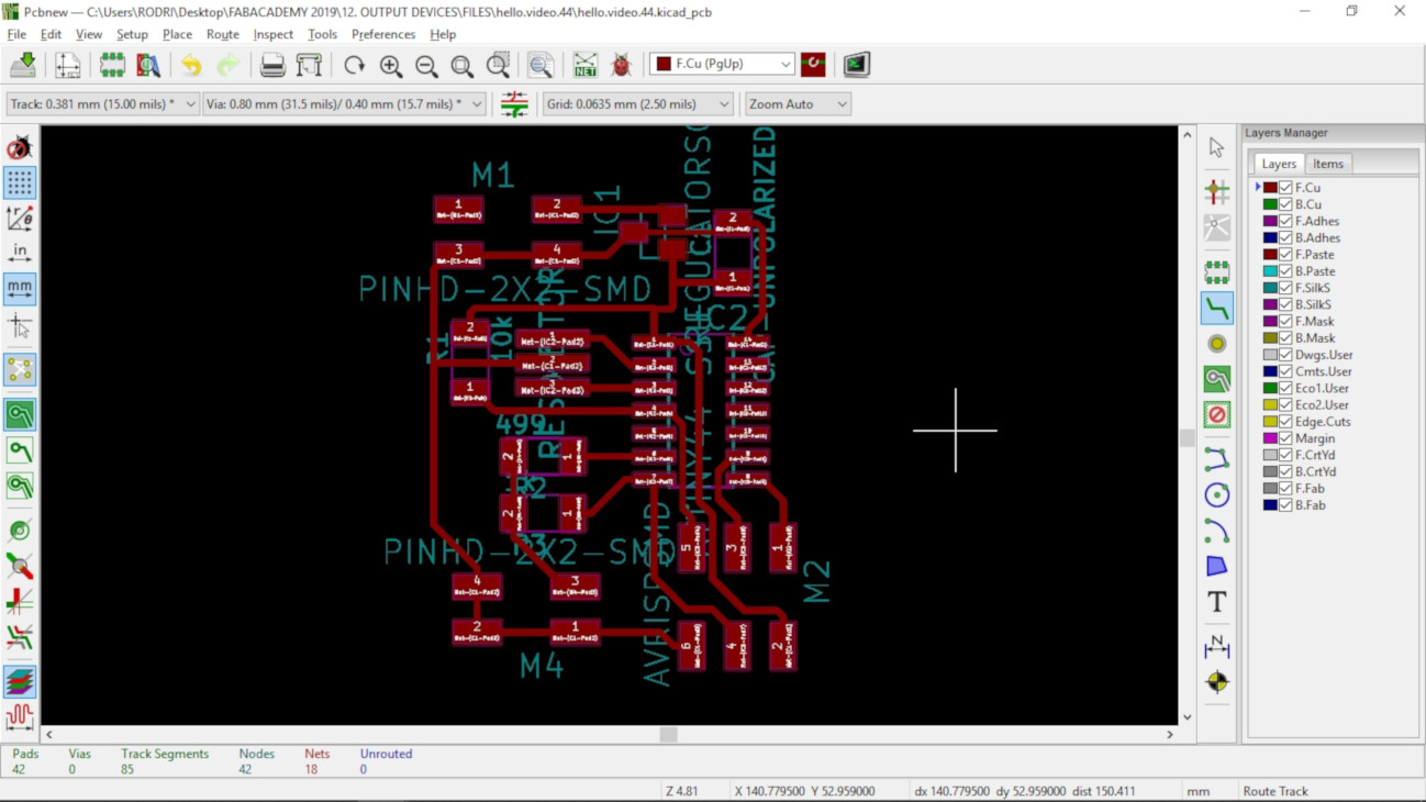
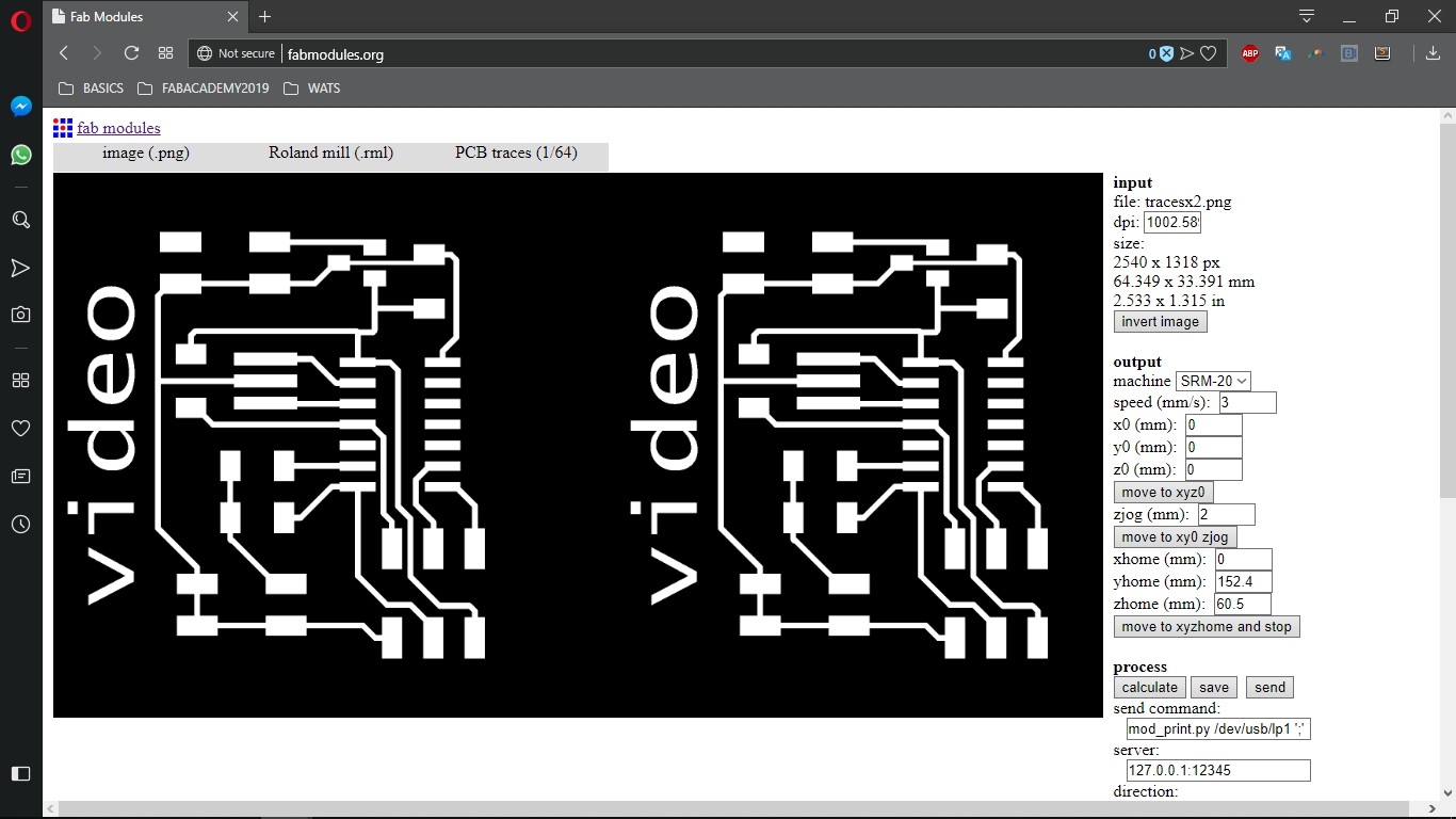
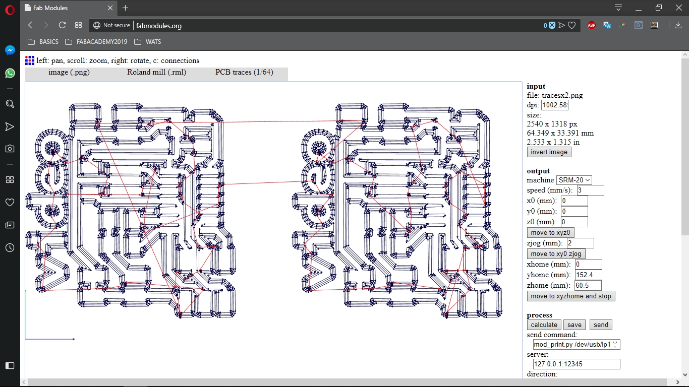
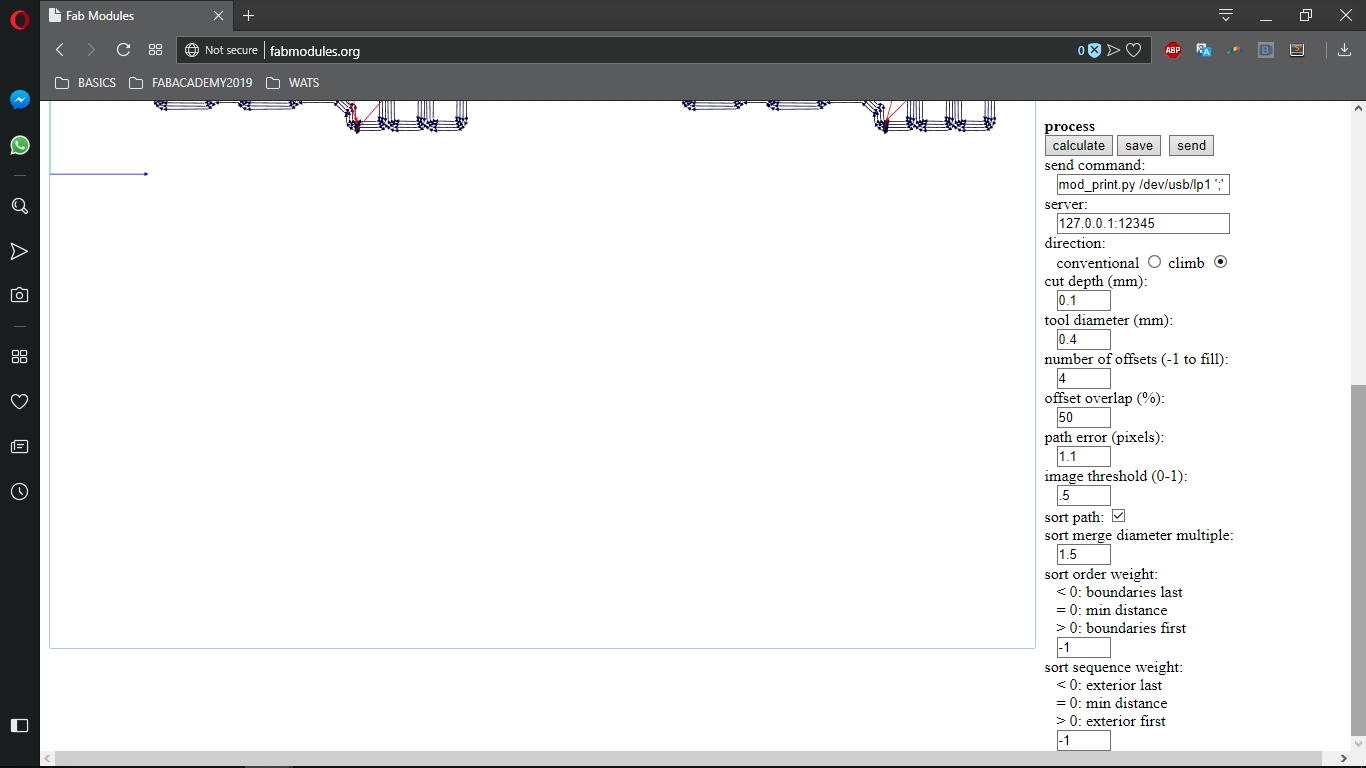
I used FabModules to generate the .rml files for the Roland SRM-20 machine.
Fabricating the board
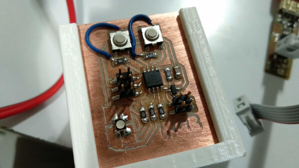
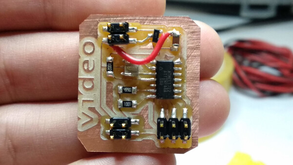
I soldered the components to the board.
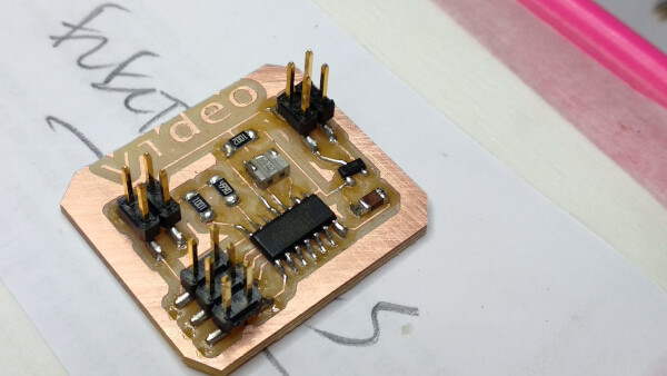
As I soldered the capacitor, I broke the trace, so I used a wire to repair it and connected it to GND.
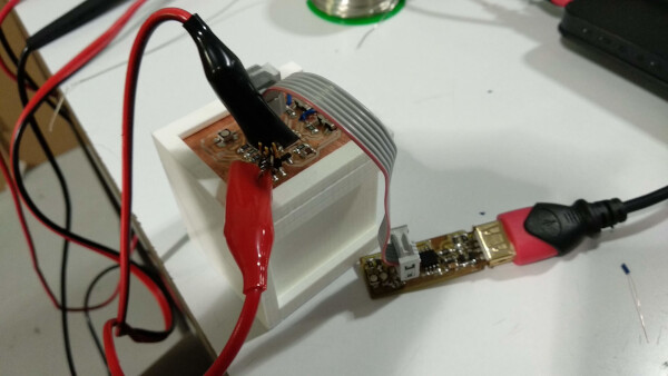
As with the RGB board, I used an external power supply for the video board, and connected the ISP pins to the FabISP to program it.
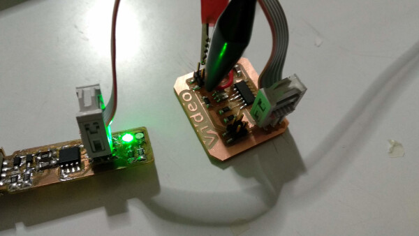
I downloaded Neil's code pasted it into the Arduino IDE and uploaded it to the video board.
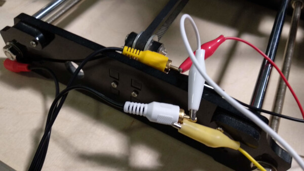
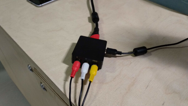
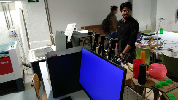
After this, I connected the output signals of the video board, to RCA connector (yellow/white/red), connected that to an HDMI converter, and plugged it into a monitor. After doing some tests the monitor kept showing a blue screen, indicating something went wrong, in my connections or in the soldering of the board. At the end I didn't have time to check what went wrong. The first step to check what is not working, is to connect the output signal of the video board to an oscilloscope, and see if it shows any signals. Until I do that, the video board still hasn' work for me.
Files
- RGB board (KiCAD Project)
- RGB board traces .png
- RGB board profile .png
- RGB board code .ino (Arduino)
- RGB rainbow code .ino (Arduino)
- Video board (KiCAD Project))
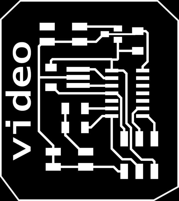
- video board traces .png
- video board profile .png
- video board code .ino (Arduino)
Group Assignment
To see this weeks group assignment click here.